Substrate Integrated Waveguide With Defected Ground Structure For Microwave Filter Design
Full text
Figure
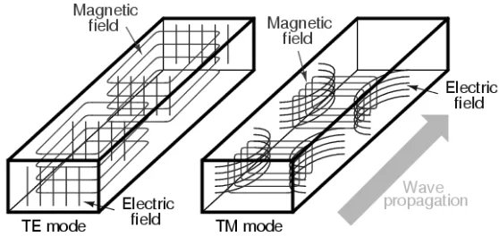
![Figure 2.3: Electric and Magnetic Fields For The TE10 Mode In Waveguide [5].](https://thumb-us.123doks.com/thumbv2/123dok_us/101691.9519/23.595.236.403.65.443/figure-electric-magnetic-fields-te-mode-waveguide.webp)
Related documents
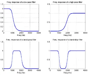
Thus, this project is to design and developed five order band-pass filter by using optimum distributed high-pass integrated with Defected Micro-strip Structure (DMS)
ANALYSIS AND DEVELOPMENT OF MULTIPLE-BAND BANDSTOP FILTER USING SUBSTRATE INTEGRATED WAVEGUIDE (SIW) TECHNOLOGY.. Sesi Pengajian :
(2014) ‘K-band substrate integrated waveguide T-junction diplexer design by mode-matching techniques’, In Proceedings of the IEEE Asia-Pacific Microwave Conference (APMC), Sandai,
SIW Substrate integrated waveguide ESIW Empty substrate integrated waveguide MSIW Modified substrate integrated waveguide AFSIW Air filled substrate integrated waveguide HSIW
[17] Chao Wang; Wenquan Che; Chao Li; Russer, P.; , "Multi-way microwave power dividing/combining network based on substrate- integrated waveguide (SIW)
By utilizing empty substrate integrated waveguide (ESIW) structure and dielectric loaded filter technology, the possibility of controlling the impedance of waveguide without the need
Using the SFSIW resonant cavity with the intermediate metal layer feeding method analyzed above, a three-cavity cross-coupled symmetric folded substrate integrated
Abstract— A Substrate integrated waveguide bandpass filter is presented with a novel CPW-to-SIW transition at both the input and output ports which also served
