Article
Impact Analyses of a Tennis Ball onto Water-Filled
Containers
Kanokporn Pintobtang a and Tumrong Puttapitukpornb,*
Department of Mechanical Engineering, Faculty of Engineering, Kasetsart University, Bangkok 10900, Thailand
E-mail: ak.pintobtang@gmail.com, bfengtop@ku.ac.th (Corresponding author)
Abstract. Water-filled containers have long known for its structural characteristic of impact load absorption. This paper presents design of structures resisting to impact load resulting from a high-velocity tennis ball. One cubic meter water containers consisting of rectangular, cylindrical, and spherical water containers and water levels were studied for their stress distribution and deformation during maximum deformation period using finite element analysis in the ANSYS 15.0 software. The containers were modeled by using shell elements and made of elasto-plastic material of HDPE plastic. The filled water was model by using fluid elements. We found that as ball velocity increased, maximum von Mises stress increased. However, for post-yielding behavior, maximum von Mises stress approached a constant near yield stress of HDPE material.As ball velocity increased, deformation increased. When water level increased, maximum deformation decreased. For the rectangular and cylindrical containers, when the water level increased, the maximum von Mises stress increased. However, in the spherical container, as water level increased, the maximum von Mises stress was not significant change. Among three water-filled containers, the rectangular container has the highest efficiency in impact absorption, followed by the cylindrical container and the spherical container respectively.
Keywords: Impact, tennis ball, water-filled containers, finite element analysis.
ENGINEERING JOURNAL Volume 21 Issue 1 Received 3 February 2016
1. Introduction
There are many attempts to improve capabilities of structures to withstand high-velocity impact loads which include development of new structural shapes, structures filled with liquid or foam, and use of new composite materials. Some researchers were interested in tapered thin-walled rectangular tubes for their high impact energy absorption [1, 2]. The liquid or foam filled inside structures had long known for their abilities to absorb and to dissipate high-velocity impact loads [3-15] Some of researches aimed to find effects of liquid levels filled inside structures on abilities to absorb impact energy [16, 17] while other focused on controlling liquid sloshing inside structures [18] or determined vibration characteristic of liquid [19] during impact. One application of liquid filled inside structure is not only to absorb impact energy but also to add weight to the structure for minimizing its structural movement commonly found in design of vehicle barriers [20, 21]. Rimdusit et al. [22] studied the use of KevlarTM fiber-reinforced polybenzoxazine
alloys for ballistic impact applications.
This paper aims to study dynamic effects of geometries of water containers and water levels on stress and deformation of water containers during impact by a high-velocity tennis ball using finite element analysis (FEA). One cubic meter water containers consisting of rectangular, cylindrical, and spherical water containers and 0%, 50%, 100% water levels were modeled in the ANSYS 15.0. The water containers were modeled by shell elements and made of elasto-plastic material of HDPE plastic while water was modeled by fluid element.
2. Materials and Methods
2.1. Analytical Models
2.1.1. Fully water-filled cylindrical container under compressive force
The mathematical model of a fully water-filled cylindrical container under compressive force at both ends which were modelled as rigid lids is shown in Fig. 1. The longitudinal displacement and maximum von Mises stress are compared to the finite element analysis to validate accuracy of the fluid-structure interaction in the FE models.
Fig. 1. The mathematical model of a fully-filled water container under compressive force. By using the principle of superposition, the external compressive force Fis written as
w c
FF F (1)
where Fwis the reaction force done by water and
F
cis the reaction force done by the cylindrical container. By neglecting static pressure of water, the water pressure results from the compressive force is
2
2w c
i
i i i i
F F F
p
r u r u
(2)
Rigid lids
[image:2.595.70.514.465.603.2]where
r
iis the inner radius andu
i is the radial displacement at the inner surface. The incompressibility of fully-filled liquid inside the container gives
2
2
i i i
r L r u L (3)
By assuming uniform longitudinal displacement
on cross–section of the cylindrical container, the longitudinal displacement can be expressed as
2
2c
o o i i
F L
E r u r u
(4)
From Hooke’s law, the radial displacement at the inner surface uiis written as
2 2
2 2 2 2
i o i c
i i i
o i o o i i
r r r F
u p p
E r r r u r u
(5)
and the radial displacement at the outer surface uois written as
2
2 2 2 2
2
o i i c
o
o i o o i i
r r p F
u
E r r r u r u
(6)
By substituting Eq.(2), Eq.(4), and Eq.(5) into Eq.(3), we have
2
2 2
2 2
2 2 2 2 2 2
1
1 1
1
c
o o i i
c o i c c
o i
i i i i o o i i
F
E r u r u F F r r F F F
E r u r r r u r u r u
(7)
, ,
c iF u
andu
ocan be obtained by numerical solving Eq. (5)-(7). The maximum von Mises stress occurring at the inner surface is given by
2
2
2max
1 2
i r r z z
r r
(8)
where
r pi
(9)
2 2 2 2 o i i o i r r p r r
(10)
2
2p z
o o i i
F
r u r u
2.1.2. Approximation of impact load
The simplest and conservative mathematical model for approximating impact load is to assume that the structure remains elastic and structural damping and internal friction were negligible. The relationship between impact force
F
and impact velocityv
of a projectile having massm
is derived from the structural stiffnessk
and the principle of energy conservation. The maximum deformationx
during impact is written as1 2 1 2
2mv 2kx (12)
2
mv x
k
(13)
The equivalent impact force is
e
F kx (14)
By substituting Eq. (13) into Eq. (14), the relationship between impact velocity and equivalent impact force was
2
e F v
km
(15)
2.2. Finite Element Models
2.2.1. Fully-filled cylindrical water container under compressive forces
A fully-filled water cylindrical container was modelled in the ANSYS V.15 software. The material properties of the container were Young’s modulus of 2.90 GPa and Poisson’s ratio of 0.42. The container was fully filled with water having bulk modulus of 2.068 GPa, viscosity of 0.0013 Pa.s, density of 1000 kg/m3, and
sonic velocity of 1450 m/s. A three-dimensional finite element model consisted of the 4-node shell element (SHELL181) and the 4-node fluid elements (FLUID80) as shown in Fig. 2. The boundary conditions were that one end of the cylindrical container was fixed and another end was subjected to compressive force of 1000 N.
The stress-strain relationship implemented into FLUID 80 element is 1
0 0 0 0 0 0
1
0 0 0 0 0 0
1
0 0 0 0 0 0
1
0 0 0 0 0 0
1
0 0 0 0 0 0
1
0 0 0 0 0 0
1
0 0 0 0 0 0
bulk
xy xy
yz yz
xz xz
x x
y y
z z
K
S P
S
S
M M B
M
B
B
where bulk strain,
bulk
u v w
x y z
(17)
ij= shear strain on plane ij, and i= rotation about axis i, P= pressure,
ij= shear stress on plane ij, iM = twist force about axis i.,
K
= fluid bulk modulus, 910
S K
(arbitrarily small number to give element some shear stability), and 9
10
B K
(arbitrarily small number to give element some rotational stability).
Damping matrix is developed based on
0 0 0 0 0 0 0
1
0 0 0 0 0 0
1
0 0 0 0 0 0
1
0 0 0 0 0 0
1
0 0 0 0 0 0
1
0 0 0 0 0 0
1
0 0 0 0 0 0
bulk
xy xy
yz yz
xz xz
x x
y y
z z
P
M
M c
M c
c
(18)
0.00001
c (19)
where = viscosity, and the dot notation representing differentiation with respect to time.
Fig. 2. FE model of the fully-filled liquid container under compressive forces. 2.2.2. Approximated impact of a tennis ball onto water containers
[image:5.595.195.430.523.686.2]1 x 1 x 1 m rectangular containers with 5 mm thickness subjected to approximated impact loads at center of the front face of containers were modelled in the ANSYS v15.0 software as shown in Fig. 3. Two FE models of containers consisting of an empty container and a fully-filled water container were used to study effects of fluid-structure interaction on stress distribution and structural deformation on containers. The containers were modelled using SHELL 181 elements which have four nodes and six degrees of freedom for each node. Filled water was modelled using FLUID 80 elements which have eight nodes and three degrees of freedom for each node. The container mesh had 29,400 elements while the filled-water mesh had 343,000 elements. This FE model was tested for convergence of FE results. The rectangular containers were made of high–density polyethylene plastic (HDPE) which was modelled as linear-elastic isotropic material [23]. The material properties of FE models are shown in Table 1. First, approximated impact loads of 5 N, 10 N, and 15 N were applied perpendicularly to the center of the front face of containers to determine their structural stiffness. The bottom of containers was fixed in all degrees of freedom.
Fig. 3. FE model of the rectangular container. Table 1. Mechanical properties.
Material Elastic Modulus (GPa) Poisson’s Ratio Stress Yield (MPa)
Density (kg/m3)
Sonic Velocity
(m/s)
HDPE 0.7 0.4 15.8 - -
Water 2.2 - - 998.3 1450
Spherical ball - - - 376.5 -
2.2.3. Dynamic impact of a tennis ball onto water containers
[image:6.595.162.435.240.445.2] [image:6.595.69.528.507.582.2]impacted by the tennis ball at initial velocity of 1-20 m/s. The water levels were 0%, 50%, and 100% of filled capacity respectively. The bottom of water containers was fixed in all degrees of freedom.
(a) Rectangular container (b) Cylindrical container
(c) Spherical container
Fig. 4. Dynamic FE models of (a) the rectangular water container, (b) the cylindrical water container, and (c) the spherical water container.
Fig. 5. True stress versus true strain of HDPE plastic.
0 10 20 30 40 50 60 70
0 0.5 1 1.5 2
T
ru
e
st
res
s
[
M
P
a]
[image:7.595.115.481.113.428.2] [image:7.595.166.433.478.678.2]Table 2. Number of elements of FE models of the rectangular water container.
Water-filled capacity (%) No. of shell elements No. of fluid elements
0 29,400 -
50 29,400 171,500
100 29,400 343,000
Table 3. Number of elements of FE models of the cylindrical water container.
Water-filled capacity (%) No. of shell elements No. of fluid elements
0 7,200 -
50 7,200 42,000
100 7,200 84,000
Table 4. Number of elements FE models of the spherical water container.
Water-filled capacity (%) No. of shell elements No. of fluid elements
0 43,200 -
50 43,200 864,000
100 43,200 1,728,000
3. Results and Discussion
3.1. Fully-filled Cylindrical Water Container under Compressive Forces
The longitudinal deformation of the container obtained from FE analysis and analytical solution were 1.701 mmand 1.658 mm respectively, which yielded error less than 2.59 percent. Maximum von Mises stress obtained from FE analysis and analytical solution were 5.091 MPa and 4.982 MPa respectively, which yielded error less than 2.19 percent. The FE model obtained accurate and acceptable results. Fig. 6 shows the von Mises stress distribution on the container.
Fig. 6. Contour plot of von Mises stress on the fully-filled water container under compressive forces.
[image:8.595.70.526.104.157.2] [image:8.595.69.528.193.245.2] [image:8.595.69.527.283.335.2] [image:8.595.154.442.471.685.2]3.2. Approximated Impact FE Models of a Tennis Ball onto Rectangular Water Containers
The relationship between approximated impact forces and maximum deformation of the rectangular water containers shows in Fig. 7. The slopes of these two lines were structural stiffnesses k which were
. 3
1 28 10 N/m for the empty water container and 1 46 10 N/m for the fully-filled water container. . 3
Fig. 7. Approximated impact force versus maximum deformation.
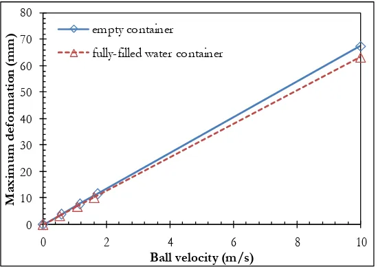
The relationship between approximated impact forces and ball velocities was given in Eq. (15). Figure 8 shows maximum von Mises stress versus ball velocity. Figure 9 shows maximum deformation versus ball velocity. When comparing FE results of fully-filled water containers to ones of empty container, the maximum von Mises stress increases while maximum deformation decreases. Figure 10 shows the stress contours of von Mises stress at the impact forces of 15 N comparing between the empty container and the fully-filled water container. These FE results showed capability of water to absorb and dissipate impact load to the rest of the container structure.
Fig. 8. Maximum von Mises stresses versus ball velocity. 0
2 4 6 8 10 12 14 16
0 2 4 6 8 10 12 14
A
pp
ro
xi
m
at
ed
im
pa
ct
fo
rce
(N
)
Maximum deformation (mm)
empty container
fully-filled water container
0 2 4 6 8 10 12 14
0 2 4 6 8 10
M
ax
im
um
v
on
M
is
es
s
tr
es
s
(M
P
a)
Ball velocity (m/s) empty container
[image:9.595.163.435.157.367.2] [image:9.595.162.436.501.696.2]Fig. 9. Maximum deformation versus ball velocity.
[image:10.595.162.437.79.273.2](a) Empty container (b) Fully-filled water container
Fig. 10. Von Mises stress distribution at 15 N approximated impact force of (a) empty container and (b) Full-filled water container.
3.3. Dynamic Impact FE Models of a Tennis Ball onto Water Containers
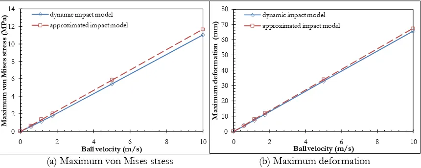
Figure 11 shows maximum von Mises stress versus ball velocity and maximum deformation versus ball velocity comparing between approximated impact models and dynamic impact model of the empty rectangular water container. The percent differences of these two FE models were less than 6% for maximum von Mises stresses and 2.9 % for maximum deformation. Figure 12 shows maximum von Mises stress versus ball velocity and maximum deformation versus ball velocity comparing between approximated impact FE models and dynamic impact model of the fully-filled rectangular water container. These FE results showed effects of energy absorption of water on structural responses resulting from viscous flow of water during impact.
In dynamic impact FE models, effects of ball velocities on water levels were investigated at the maximum deformation period. The plots of maximum von Mises stress versus ball velocity and maximum deformation versus ball velocity for each water container are shown in Fig. 13-15. It was found that as ball velocity increased, maximum von Mises stress increased. However, for post-yielding behaviour, maximum von Mises stress approached a constant near yield stress of HDPE plastic. At ball speed of 20 m/s, the maximum deformations on the full-filled rectangular, cylindrical and spherical water containers were 91.75%, 70.99% and 51.21% lower than ones of empty containers respectively. Here, water showed ability to suppress impact deformation especially in fully-filled rectangular container. For the rectangular and cylindrical containers, when the water level increased, the maximum von Mises increased. However, in the
0 10 20 30 40 50 60 70 80
0 2 4 6 8 10
M
ax
im
um
d
ef
or
m
at
io
n
(m
m
)
Ball velocity (m/s) empty container
[image:10.595.79.520.306.491.2]spherical container, when the water level increased, the maximum von Mises stress was not significant change.
Figures 16-18 show contour plots of von Mises stress distribution on water containers for various water levels at ball velocity of 5 m/s. Figures 19-21 show contour plot of deformation in the direction of impact on containers for various water levels at ball velocity of 5 m/s. It was found that the maximum deformation and maximum von Mises stresses arose at center of impact and stress wave spread out toward edges of water containers.
The plots of maximum von Mises stress versus ball velocity and maximum deformation versus ball velocity compared between each water container are shown in Fig. 22-24. At 0% and 50% filled capacities, the spherical container has lowest deformation and highest von Mises stress. At 100% filled capacity, the maximum von Mises stress and maximum deformation on the cylindrical and spherical containers are not slightly difference.
[image:11.595.84.514.240.412.2](a) Maximum von Mises stress (b) Maximum deformation
Fig. 11. Comparison between approximated and dynamic impact models of the empty rectangular container (a) maximum von Mises stress versus ball velocity and (b) maximum deformation versus ball velocity.
(a) Maximum von Mises stress (b) Maximum deformation
Fig. 12. Comparison between approximated and dynamic impact models of the fully-filled rectangular container (a) maximum von Mises stress versus ball velocity and (b) maximum deformation versus ball velocity. 0 2 4 6 8 10 12 14
0 2 4 6 8 10
M axi m u m v on M is es s tr es s (M P a)
Ball velocity (m/s)
dynamic impact model approximated impact model
0 10 20 30 40 50 60 70 80
0 2 4 6 8 10
M axi m um d ef or m ati on ( m m )
Ball velocity (m/s)
dynamic impact model approximated impact model
0 2 4 6 8 10 12 14 16 18
0 2 4 6 8 10
M axi m um v on M is es s tr es s (M P a)
Ball velocity (m/s)
dynamic impact model approximated impact model
0 2 4 6 8 10 12
0 2 4 6 8 10
M axi m um d ef or m ati on ( m m )
Ball velocity (m/s)
[image:11.595.82.514.473.641.2](a) Maximum von Mises stress (b) Maximum deformation
Fig. 13. FE results of dynamic impact of a tennis ball onto the rectangular water containers at maximum deformation period (a) maximum von Mises stress versus ball velocity and (b) maximum deformation versus ball velocity.
[image:12.595.81.517.311.478.2](a) Maximum von Mises stress (b) Maximum deformation
Fig. 14. FE results of dynamic impact of a tennis ball onto the cylindrical water containers at maximum deformation period (a) maximum von Mises stress versus ball velocity and (b) maximum deformation versus ball velocity.
(a) Maximum von Mises stress (b) Maximum deformation
Fig. 15. FE results of dynamic impact of a tennis ball onto the spherical water containers at maximum deformation period (a) maximum von Mises stress versus ball velocity and (b) maximum deformation versus ball velocity.
0 5 10 15 20 25 30 35
0 5 10 15 20
M ax im um d ef or m at io n (m m )
Ball velocity (m/s)
0% filled capacity 50% filled capacity 100% filled capacity
0 2 4 6 8 10 12 14 16 18
0 5 10 15 20
M ax im um v on M is es s tr es s (M P a)
Ball velocity (m/s)
0% filled capacity 50% filled capacity 100% filled capacity
0 2 4 6 8 10 12 14 16 18 20
0 5 10 15 20
M ax im um d ef or m at io n (m m )
Ball velocity (m/s)
0% filled capacity 50% filled capacity 100% filled capacity
0 2 4 6 8 10 12 14 16 18
0 5 10 15 20
M ax im um v on M is es s tr es s (M P a)
Ball velocity (m/s)
[image:12.595.85.514.544.714.2](a) 0% filled capacity (b) 50% filled capacity (c) 100 % filled capacity
Fig. 16. Von Mises stress distribution on rectangular water containers for various water levels at ball velocity of 5 m/s.
[image:13.595.80.523.263.389.2](a) 0% filled capacity (b) 50% filled capacity (c) 100 % filled capacity
Fig. 17. Von Mises stress distribution on cylindrical water containers for various water levels at ball velocity of 5 m/s.
(a) 0% filled capacity (b) 50% filled capacity (c) 100 % filled capacity
Fig. 18. Von Mises stress distribution on spherical water containers for various water levels at ball velocity of 5 m/s.
(a) 0% filled capacity (b) 50% filled capacity (c) 100 % filled capacity
[image:13.595.79.520.434.561.2] [image:13.595.78.521.606.734.2](a) 0% filled capacity (b) 50% filled capacity (c) 100 % filled capacity
Fig. 20. Contour plot of deformation in the direction of impact on cylindrical water containers for various water levels at ball velocity of 5 m/s.
[image:14.595.82.522.263.389.2](a) 0% filled capacity (b) 50% filled capacity (c) 100 % filled capacity
Fig. 21. Contour plot of deformation in the direction of impact on spherical water containers for various water levels at ball velocity of 5 m/s.
(a) Maximum von Mises stress (b) Maximum deformation
Fig. 22. Comparison of FE results on 0% water-filled containers (a) maximum von Mises stress versus ball velocity and (b) maximum deformation versus ball velocity.
0 20 40 60 80 100 120 140 160 180
0 5 10 15 20
M
ax
im
um
d
ef
or
m
at
io
n
(m
m
)
Ball velocity (m/s)
the rectangular container
the cylindrical container
the spherical container
0 2 4 6 8 10 12 14 16 18 20
0 5 10 15 20
M
ax
im
um
v
on
M
is
es
s
tr
es
s
(M
P
a)
Ball velocity (m/s)
[image:14.595.87.514.437.617.2](a) Maximum von Mises stress (b) Maximum deformation
Fig. 23. Comparison of FE results on 50% water-filled containers (a) maximum von Mises stress versus ball velocity and (b) maximum deformation versus ball velocity.
(a) Maximum von Mises stress (b) Maximum deformation
Fig. 24. Comparison of FE results on 100% water-filled containers (a) maximum von Mises stress versus ball velocity and (b) maximum deformation versus ball velocity.
4. Conclusion
This paper investigated impact behaviors of one cubic meter of water containers consisting of the rectangular, cylindrical, and spherical containers by a high-velocity tennis ball. The mathematical model of a fully-filled cylindrical water container under compressive forces was created and its results were compared to FE results for evaluating of FE accuracy of quasi static analyses. We found that error of FE model was less than 2.19 % on maximum von Mises stress and 2.59 % on maximum deformation. In FE analyses of a tennis ball impacting onto rectangular water containers, the approximated impact FE models were compared to the dynamic impact FE models for evaluating accuracy of dynamic analyses. We found good agreement of these models on empty rectangular water containers in which the percent differences of these two FE models were less than 6% on maximum von Mises stresses and 2.9 % on maximum deformation. In dynamic impact FE analyses of a tennis ball impacting onto the rectangular and cylindrical containers, when the water level increased, the maximum von Mises stress increased. However, in the spherical container, as water level increased, the maximum von Mises stress was not significant change. Among three water-filled containers, the rectangular container has the highest efficiency in impact absorption, followed by the cylindrical container and the spherical container respectively.
0 2 4 6 8 10 12 14 16 18 20
0 5 10 15 20
M ax im um v on M is es s tr es s (M P a)
Ball velocity (m/s)
the rectangular container
the cylindrical container
the spherical container
0 5 10 15 20 25
0 5 10 15 20
M ax im um d ef or m at io n (m m )
Ball velocity (m/s)
the rectangular container
the cylindrical container
the spherical container
0 2 4 6 8 10 12 14 16 18 20
0 5 10 15 20
M ax im um v on M is es s tr es s (M P a)
Ball velocity (m/s)
the rectangular container the cylindrical container the spherical container
0 2 4 6 8 10 12
0 5 10 15 20
M ax im um d ef or m at io n (m m )
Ball velocity (m/s) the rectangular container
[image:15.595.84.517.314.496.2]References
[1] G. M. Negel and D. P. Thambiratnam, “Computer simulation and energy absorption of tapered thin-walled rectangular tubes,” Thin-Wall Struct, vol. 43, pp. 1225-1242, 2005.
[2] C. Qi, S. Yang, and F. Dong, “Crushing analysis and multiobjective crashworthiness optimization of tapered square tubes under oblique impact loading,” Thin-Wall Struct, vol. 59, pp. 103-119, Jun. 2012. [3] M. D. Goel, “Deformation, energy absorption and crushing behavior of single-, double- and
multi-wall foam filled square and circular tubes,” Thin-Wall Struct, vol. 90, pp. 1-11, 2015.
[4] D. Varas, J. López-Puente, and R. Zaera, “Experimental analysis of fluid-filled aluminum tubes subjected to high-velocity impact,” Int J Impact Eng, vol. 36, pp. 81-91, May 2008.
[5] S. Yang and C. Qi, “Multiobjective optimization for empty and foam-filled square columns under oblique impact loading,” Int J Impact Eng, vol. 54, pp. 177-191, 2013.
[6] S. Hou, Q. Li, S. Long, X. Yang, and W. Li, “Crashworthiness design for foam filled thin-wall structures,” Mater Des, vol. 30, pp. 2024-2032, 2009.
[7] Z. Li, J. Yu, and L. Guo, “Deformation and energy absorption of aluminum foam-filled tubes subjected to oblique loading,” Int J Mech Eng, vol. 54, pp. 48-56, 2012.
[8] J. Bi, H. Fang, Q. wang, and X. Ren, “Modeling and optimization of foam-filled thin-walled columns for crashworthiness designs,” Finite Elem Anal Des, vol. 46, pp. 698-709, 2010.
[9] F. Djamaluddin, S. Abdullah, A. K. Ariffin, and Z. M. Nopiah, “Optimization of foam-filled double circular tubes under axial and oblique impact loading conditions,” Thin-Wall Struct, vol. 87, pp. 1-11, 2015.
[10] I. Thiyahuddin, Y. T. Gu, D. P. Thambiratnam, and P. Gudimetla, “Impact & energy absorption of road safety barriers by couple SPH/FEM,” International Journal of Protective Structures, vol. 3, no. 3, pp. 257-274, 2012.
[11] G. Lu, J. Lei, Z. Han, Z. Liu, and S. Zhang, “Denting and failure of liquid-filled tubes under lateral impact,” Acta Mechanica Solida Sinica, vol. 25, no. 6, pp. 609-615, Dec. 2012.
[12] Y. Wang and H. Zhou, “Numerical study of water container under blast loading,” Thin-Wall Struct, vol. 90, pp. 42-48, 2015.
[13] Y. Wang and S. C. Lee, “Experimental study of water container under impulsive loading,” Arch Civ Mech Eng, vol. 15, pp. 986-996, 2015.
[14] Q. H. Shah, “Experimental and numerical study on the orthogonal and oblique impact on water filled pipes,” Int J Impact Eng, vol. 38, pp. 330-339, 2011.
[15] Y. Wang, J. Y. Richard Liew, and S.C. Lee, “Structural performance of water container under static and dynamic pressure loading,” Int J Impact Eng, vol. 85, pp. 110-123, 2015.
[16] M. J. Jhung, J. C. Jo, and S. J. Jeong, “Impact analysis of a water storage container,” Nucl Eng Technol, vol. 38, no. 7, pp. 110-123, Oct. 2006.
[17] I. Thiyahuddin, D. P. Thambiratnam, Y. T. Gu, and R. B. Gover, “Safety enhancement of water-filled road safety barrier using interaction of composite materials,” in Quality in Research Proceedings, Yogyakarta, Indonesia, 2013.
[18] M. Amiri and S. R. Sabbagh-Yazdi, “Ambient vibration test and finite element modeling of tall liquid storage containers,” Thin-Wall Struct, vol. 49, pp. 974-983, 2011.
[19] M. Anghileri, L. M. L. Castelletti, and M. Tirelli, “Fluid-structure interaction of water filled tanks during the impact with the ground,” Int J Impact Eng, vol. 31, pp. 235-254, 2005.
[20] I. Thiyahuddin, Y. T. Gu, R. B. Gover, and D. P. Thambiratnam, “Fluid–structure interaction analysis of full scale vehicle-barrier impact using coupled SPH–FEA,” Eng. Anal. Bound. Elem., vol. 42, pp. 26-36, 2014.
[21] F. Tarlochan, F. Samer, A. M. S. Hamouda, S. Ramesh, and K. Khalid, “Design of thin wall structures for energy absorption applications: Enhancement of crashworthiness due to axial and oblique impact forces,” Thin-Wall Struct, vol. 71, pp. 7-17, 2013.
[22] S. Rimdusit, S. Pathomsap, P. Kasemsiri, C. Jubsilp, and S. Tiptipakorn, “KevlarTM fiber-reinforced
polybenzoxazine alloys for ballistic impact applications,” Engineering Jounal, vol. 15, no. 4, pp. 23-40, 2011
[24] C. Chaowanich, (2004). Tennis Ball. [Online]. Available: