1
UNIVERSITI TEKNIKAL MALAYSIA MELAKA
SIMULATION OF AUTOMATION OF PEN CAPPING
PROCESS FOR EK300 AT SPARKLE PRESCISION SDN.
BHD.
This report submitted in accordance with requirement of the Universiti Teknikal Malaysia Melaka (UTeM) for the Bachelor Degree of Manufacturing Engineering
(Bachelor Degree of Manufacturing Engineering Process) (Hons.)
NOR MOHD UZAIR BIN NORSAHPERI B051010229
890327045145
2 “I hereby declare that I have read this thesis and in my opinion this thesis is sufficient in terms of scope and quality for the award of Bachelor of Engineering Manufacturing (Process)”.
Signature : ………
Name : Prof. Madya Dr Md Nizam Bin Abd Rahman
3 “I declare that this is my own work except for excerpts and summaries of each every one of them was me explain the source”.
Signature : ………
4
DEDICATION
For my beloved family: Norsahperi Bin Johari Noor Hayah Bte Jantan
Nor Ashraf Bin Norsahperi (Brother) Nor Ashafiq Bin Norsahperi (Brother) Nor Mohd Haziq Bin Norsahperi (Brother)
And
5
ACKNOWLEDGEMENTS
First of all, I would like to express my appreciation and gratitude to Allah S.W.T for giving me the strength and ability to carry out the entire task and work given. It is with great pleasure and gratitude that I knowledge the many people whose expertise, advice, and encouragement contributed immensely toward the completion of my Final Year Project.
Many people have contributed to the success of my Final Year Project program. To begin with, I would like to thank my supervisor Prof Dr Md Nizam Bin Abd Rahman, factory supervisor, Mr Mohd Ali Hanapiah Mohamad Nor, like as Manager, Production SPSB and Assistant Manager, Production SPSB, Mr Nizaruddin Bin Haji Zakaria, who gave the most thorough and constructive support of my project.
My thanks and appreciation also goes to all technicians, my training friends and other SPSB staff, that had supplied thought, advice, challenges, criticism, help and suggestions that have influenced my performance and increase my knowledge and understanding upon completing my Final Year Project.
6
ABSTRAK
7
ABSTRACT
8
TABLE OF CONTENT
SUPERVISOR DECLARATION i
STUDENT DECLARATION ii
DEDICATION iii
ACKNOWLEDGEMENT v
ABSTRACT vi
ABSTRAK vii
TABLE OF CONTENT viii
LIST OF TABLE xi
LIST OF FIGURE xii
CHAPTER 1: INTRODUCTION 1
1.1 Introduction. 1
1.2 Problem Statement 1
1.3 Objective 2
1.4 Scope 2
1.5 Gant Chart 3
CHAPTER 2: LITERITURE REVIEW 5
2.1 Company Background 5
9 2.3 Approaches in Capping Process Implementation
2.3.1 Summary of Capping Process Implementation
10 12
2.4 Approaches in Automation Implementation 2.4.1 Summary of Automation review
12 14 2.5 Modelling of Automation System
2.5.1 Summary of Motion Design
14 17
CHAPTER 3: METHODOLOGY 18
3.1 Flow Chart of Methodology 18
3.2 Industrial Visit 20
3.3 Machine Design 22
3.4 PLC System Developing 23
3.5 Return of Investment Analysis 25
CHAPTER 4: RESULT AND DISCUSSION 26
4.1 Machine Design 26
4.2 Motion Study 27
4.3 PLC Programming Developing 28
4.4 Cycle Time Analysis 45
4.5 ROI Analysis 46
CHAPTER 5: CONCLUSION AND RECOMMENDATION 47
REFERRENCE 49
10
LIST OF TABLES
1.1: Activities Schedule 3
1.2: Graphical Process Description in Product Assembly Using EK300 7
2.3: Data Collection during Motion Study 16
11
LIST OF FIGURES
2.1: Flow Chart of Work To produce EK300 5
2.2: Part of EK300 6
2.3: Part of the Machine 6
2.4: Fixture for Pen Assemble Process 10
2.5: Figure 2.5: Fixture of Pen Assembly
2.6: Computer Vision during Quality Inspection
10 12 2.7: Blending System for Concrete Blending Process 12
2.8: Motion in Virtual Reality Box 14
2.9: Piston Motion Study In Solidwork 15
3.1: Flow Chart for Research 18
3.2: Flowchart of Solidwork Motion Study 20
3.3: Flowchart of Developing PLC Ladder Diagram. 21
4.1: Machine Body 22
4.2: Belt 23
4.3: Pulley 23
4.4: Cylinder 24
4.5: Assemble of Machine 24
4.6: First Motion of EK300 25
4.7: Inserting Filter, Plug, Nib and Cap into Body 26
4.8: PLC Programming of Assembly Machine 27
4.9: Simulation of Programming (Switch on) 28
4.10: Simulation of Cylinder 1 (Extract) 29
4.11: Simulation of Cylinder 1 (Fully Extract) 30
4.12: Simulation of Cylinder 1 (Retract) 31
4.13: Simulation of Cylinder 1 (Fully Retract) 32
4.14: Simulation of Cylinder 2(Extract) 33
4.15: Simulation of Cylinder 2(Fully Extract) 34
4.16: Simulation of Cylinder 2 (Retract) 35
4.17: Simulation of Cylinder 2 (Fully Retract) 36
12
4.19: Simulation of Cylinder 3 (Fully Extract) 38
4.20: Simulation of Cylinder 3 (Retract) 39
4.21: Simulation of Cylinder 3 (Fully Retract) 40
4.22: Simulation of Cylinder 4 (Extract) 41
4.23: Simulation of Cylinder 4 (Fully Extract) 42
4.24: Simulation of Cylinder 4 (Retract) 43
13
CHAPTER 1
INTRODUCTION
1.1 Introduction
Sparkle Precision Sdn Bhd is a company that manufactures office stationary such as highlight, marker pen and ink. This company main process is shaping plastic using Injection Molding Process. This company also partners with Shachihata (Malaysia) Sdn. Bhd. Sparkle Precision Sdn. Bhd. divides its operation into three departments which are molding department, assembly department and ink department.
One of Sparkle Precision Sdn. Bhd.’s products is pen model EK 300. The manufacturing line to produce this product consists of automated and manual manufacturing cells. The entire line is manned by two operators. Since the assembly line is not fully automated, the output for manual cell of the line is significantly less than that of the automated parts of the manufacturing cell. Because of that, the manual cell becomes the bottleneck of the manufacturing lines causing intermittent stoppage of the automated line. In addition to that, the manual cell also causes high rejection since the pen capping process was in manual approached.
1.2 Problem Statement
14 this, the operator has to work faster, causing fatigue and carelessness which contributed to high product defects.
1.3 Objective
In order to solve the imbalance between manual and automated sections of the manufacturing lines, the overall aim of this project is to resolve the bottleneck issue at manual capping process. The specific objectives of this project are
To design the automated capping process To simulate the automated capping process
To perform the ROI analysis of the automated line proposal.
1.4 Scope
15
CHAPTER 2
LITERITURE REVIEW
This chapter provides the basic knowledge for the project finding by researchers and the methodology used by other researchers was summarized. This chapter also includes a SPSB background.
2.1 Company Background
16
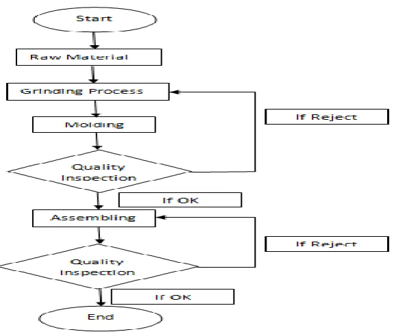
Figure 2.1: Flow Chart of Work To produce EK300
Figure 2.1 shows the process for EK300. During the manufacturing and assembling process, quality inspections were done twice in order to make sure that the marker pens produced are of high quality and fulfill customer requirement. In assembly team, a multiple sub process was involved in order to produce EK300. All process has a standard procedure to prevent unsystematic work flow and decrease reject.
2.2 Assembling Process of EK300
17
Figure 2.2: Part of EK300
[image:17.595.148.552.395.721.2]Figure 2.2 shows six components of EK300 product. All the components were assembled using the automated assembling machine. The automated assembly station assembles plug, filter and nib to the body of the marker pen. The capping process utilizes manual system.
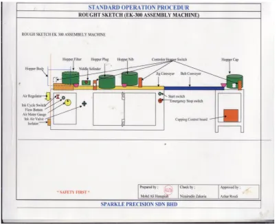
Figure 2.3: Part of the Machine
Plug
Filter Body
18 Figure 2.3 shows a layout of EK300 assembly line. Hopper body is used as a body storing part. Conveyor duty is to be transported body from one process to another process. Hopper nib, plug, filter and cap are used to storing each part based on their part. Automated assembly machine is utilized up to the nib assembly only. The capping process is manually done.
Table 2.1: Graphical Process Description in Product Assembly Using EK300
Figure Procedure
Pen body in machines hopper. This process is fully automated system.
19 Body transports to the plug by
conveyor.
This is fully automated system
20 Cap assembles by operator.
This is a fully manual system.
EK300 ready for packing and send to the customer.
2.3 Approaches in Capping Process Implementation.
This review summarized studies on capping process implementation in manual and automated mode for various products in relation to this research. Journal and article from another researcher were studied in order to identify possible approach that can be adopted for this research.
21 the pen assembly process. The locator has a fool proving design for preventing orientation mistake by the operator.
[image:21.595.109.566.219.375.2]According to Andrew D. (2008), the method to assemble pen parts is using semi automated system. This device uses electrical energy to move the cylinder to assemble the pen parts. The manual procedure in this method is all pen parts need to place at the locator by the operator.
Figure 2.4: Fixture for Pen Assemble Process (Andrew, 2008)
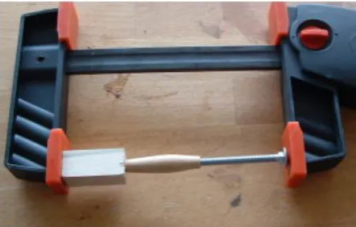
Bella V. (2009) studied a manual assembly of the pen using special fixtures as shown in Figure 2.5.
Figure 2.5: Fixture of Pen Assembly(Bella, 2009)
Cylinder
Locator
[image:21.595.207.466.488.653.2]22 Figure 2.5 shows the fixture of pen assembly by Bella V. This fixture was designed with locator and fool proving to prevent the operator place the pen in the wrong orientation.
Jeremy L.Z. (2008) studied a fully automated system by inserting ink in cartridge processing. Based on time study done after the implementation of the automation system, output for ink cartridge insertion process improved by 64 units per minute. The automated system has been designed using components such as sensor, cylinder, coil relay and limit switch.
2.3.1 Summary of Capping Process Implementation
After studying a journal and paper base on time study, the automated system was selected in order to fulfil the objective of this research. The automated system can increase the output of the capping assembly process.
2.4 Approaches in Automation Implementation
According to Groover P.M. (2008), automated can be explained by some system that can run the process or procedure without human assistance. Automated technology can be divided by 3 types which is numerical control, robotic technology and programmable logic controller.
23
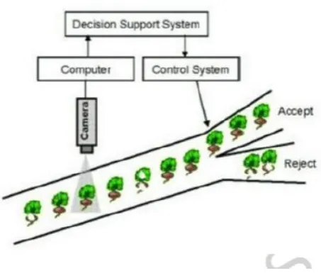
Figure 2.6: Computer Vision during Quality Inspection (Gunasekaran , 2005)
Figure 2.6 shows a computer vision during quality inspection in the quality inspection process. It uses computer vision to inspect a reject of the product. This method is useful in a mass production process.
24
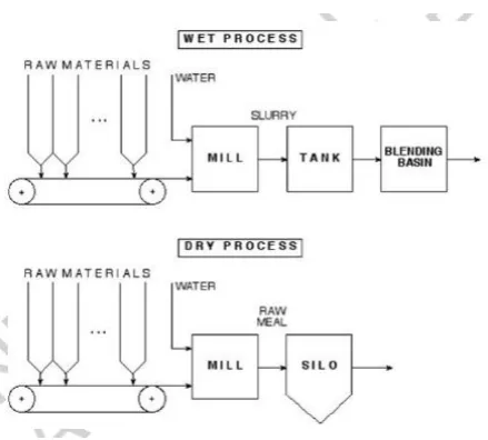
Figure 2.7: Blending System for Concrete Blending Process (Keviczky, 2009)
Figure 2.7 shows about blending system for the concrete blending process. It uses a conveyor as transporting material. All process is controlled by PLC system. Since all process is automated system, 3 operators need to control the process.
According to James M. (2007), semiconductor can be manufactured perfectly by using a computer integrated manufacturing system (CIM). This system was used a CNC system where CNC system will control the movement of the machine. This system is suitable for accuracy of dimension and mass production is a main issue for certain process.
2.4.1 Summary of Automation review