NUR AMALINA BINTI AHMAD NAWIR
iii
DEVELOPMENT OF THE HOME APPLIANCES CONTROLLER BASED ON DTMF SIGNAL
NUR AMALINA BINTI AHMAD NAWIR
This report is submitted in partial fulfillment of the requirements for the degree of Bachelor of Electronic Engineering (Industrial Electronics) With Honours
Faculty of Electronic and Computer Engineering Universiti Teknikal Malaysia Melaka
Tajuk Projek
BORANG PENGESAHAN STATUS LAPORAN
PROJEK SARJANA MUDA II
'q~ .. t?r¥f.~!~~~ ... .
Sesi Pengajian
Saya .. ~~~. ~M~.':-~~~ .. ~!~.1 .. ~~t> -~~! ~ ... .. (HURUF BESAR)
mengaku membenarkan Laporan Prnjek Sarjana Muda ini disimpan di Perpustakaan dengan syarat-syarat kegunaan seperti berikut:
1. Laporan adalah hakmilik Universiti Teknikal Malaysia Melaka.
2. Perpustakaan dibenarkan membuat salinan untuk tujuan pengajian sahaja.
3. Perpustakaan dibenarkan membuat salinan laporan ini sebagai bahan pertukaran antara institusi
pengajian tinggi.
4. Sila tandakan ( --.J ) :
D
SULIT*D
TERHAD**0
TIDAK TERHAD(TANDATANGAN PENULIS)
Tarikh: ...
~/¥4().f.~
.
'
*(Mengandungi maklumat yang berdarjah keselamatan atau
kepentingan Malaysia seperti yang tennaktub di dalam
AKTA RAHSlA RASMI 1972)
**(Mengandungi maklumat terhad yang telah ditentukan oleh organisasi/badan di mana penyelidikan dijalankan)
(COP
DECLARATION
I declare that this report entitled "Development of Home Appliances Controller Based
on DTMF Signal" is the result of my own work except for quotes as cited in the
refer-ences.
Signature
Author
I hereby declare that I have read this thesis and in my opinion this thesis is sufficient in terms of scope and quality for the award of Bachelor of Electronic Engineering
(Industrial Electronic) with Honours.
Signature
Supervisor Name
DEDICATION
To my beloved
parents
siblings
ABSTRACT
ii
ABSTRAK
ACKNOWLEDGEMENTS
"In the name of Allah, MostGracious, Most Merciful"
First and for most, praise to Allah S.W.T, for His blessing that giving me to
com-plete my full project report.
The satisfaction that accompanies the successful completion of the task would be
incomplete without the mention of the people who made it possible, whose constant
guidance and encouragement crown all the effort with success.
I would like to express heartfelt thanks to Dr. Ahmad Sadhiqin bin Mohd Isira,
my helpful project supervisor for his valuable guidance, and encouragement durin my
project. He inspired me greatly to work in this project. His willingness to motivate,
intense support and generous advice, which helped me in completing the project work,
in time.
I also would like to take this opportunity to express a deep sense of gratitude
to Universiti Teknikal Malaysia Melaka for giving me chance to undergo this Final
Year Project as partial fulfillment for my Degree courses. Thanks again to Universiti
Teknikal Malaysia Melaka for providing me with a good environment and facilities to
complete this project.
Finally, an honorable mention goes to my families and friends for their continuous
iv
TABLE OF CONTENTS
Declaration
Approval
Dedication
Abstract i
Abstrak ii
Acknowledgements iii
Table of Contents iv
List of Tables viii
List of Figures ix
CHAPTER 1 INTRODUCTION 1
1.1 Project Overview 1
1.2 Project Objectives 3
1.3 Problem Statement 3
1.4 Scope of Project 4
1.5 Report Structure 6
CHAPTER 2 LITERATURE REVIEW
2.1 Introduction 7
2.2 History of Home Automation 7
2.4 Dual-Tone Multi Frequency (DTMF) 10
2.5 DTMF Communication Unit 13
2.5.1 DTMF Detection 13
2.5.2 DTMF Detection Methods 14
2.5.3 IC8880 DTMF Decoder 14
2.5.3.1 General Implementation 16
2.5.4 H11AA4 17
2.6 Central Control Unit 18
2.6.1 Circuit Operation 18
2.6.2 PIC16F873 Microcontroller 18
2.6.2.1 General Implementation 20
2.7 Client Appliances Unit 20
2.7.1 Device Switching Section 21
2.7.1.1 Relay Switching Device 21
2.7.1.2 Relay Driver ULN2003 22
2.8 Software 23
2.8.1 Proteus 8 Professional 23
2.8.2 MPLAB 24
CHAPTER 3 PROJECT METHODOLOGY
3.1 Introduction 25
3.2 General Process Flow 25
3.3 Planning Stage 28
3.3.1 Data Collection 28
3.3.2 Hardware Requirement 29
3.4 General System Description 30
vi
3.5.1 DTMF Communication Unit Circuit 31
3.5.2 Central Control Unit Circuit 33
3.5.3 Client Appliances Unit Circuit 35
3.5.4 Implementation 36
3.5.4.1 Testing Circuit on breadboard 36
3.5.4.2 Design the Printed Circuit Board (PCB) 37
3.5.4.3 UV and Fabrication Process 41
3.5.4.4 Drilling and Soldering Process 44
3.6 Software Design 45
3.6.1 General Process Flow 45
3.6.2 Program Process Flow 46
3.6.3 Implementation 48
3.7 Prototype Design 50
3.7.1 Process Flow 50
3.7.2 Implementation 51
CHAPTER 4 RESULT
4.1 Introduction 55
4.2 DTMF Communication Unit 55
4.3 Central Control Unit 57
4.4 Client Appliances Unit 58
4.5 Software Result 61
CHAPTER 5 DISCUSSION
5.1 Discussion 63
CHAPTER 6 CONCLUSION AND FUTURE WORK
6.2 Conclusion 66
6.3 Future Work 67
References 69
APPENDICES 71
APPENDIX A MICROCHIP PIC16F873 72
APPENDIX B CALIFORNIA MICRO DEVICES IC8880 81
APPENDIX C FAIRCHILD SEMICONDUCTOR H11AA4 85
viii
LIST OF TABLES
Page
Table 1.1 User’s Home Control System Number Code 5
Table 2.1 The DTMF data into BCD digits [10] 15
Table 3.1 The List of Components 29
LIST OF FIGURES
Page
Figure 1.1 Scope of Work Diagram 4
Figure 2.1 4x4 Matrix Keypad [8] 10
Figure 2.2 DTMF Frequency Spectrum [9] 11
Figure 2.3 Digit-1 tone generation example for 320 samples, 40ms.(a)
Row tone at 697Hz at unity amplitude. (b) Column tone at 1209
Hz at unity amplitude. (c) Combiend tones for digit-1 [9]. 12
Figure 2.4 The DTMF Detection Filter Scheme [9] 14
Figure 2.5 The IC8880 DTMF Decoder [10] 15
Figure 2.6 The IC8880 Single End Input Connection [10] 16
Figure 2.7 The H11AA4 Optocoupler Schematic [11] 17
Figure 2.8 Pin Diagram of PIC16F873 [12] 19
Figure 2.9 Block Diagram of Central Control Unit [12] 20
Figure 2.10 The Relay with printed internal circuit [13] 22
Figure 2.11 Pin Diagram of ULN2003 [13] 23
Figure 2.12 Proteus Design Suite 8 Professional 24
Figure 2.13 MPLAB X IDE logo 24
Figure 3.1 The Methodology Flowchart 26
Figure 3.2 Block Diagram of Home Appliances Controller 30
x
Figure 3.4 DTMF Communication Unit Circuit 33
Figure 3.5 Central Control Unit Circuit 34
Figure 3.6 Client Appliances Unit Circuit 36
Figure 3.7 Picking Component from library 37
Figure 3.8 "Pick Devices" window 38
Figure 3.9 Searching for the component 38
Figure 3.10 Preview Component 39
Figure 3.11 Component already being placed 39
Figure 3.12 Wiring up the component 40
Figure 3.13 The PCB layout of the PIC16F873 40
Figure 3.14 3D illustration of PCB board 41
Figure 3.15 PCB Circuit Layout 42
Figure 3.16 Remove sticker from the PCB 42
Figure 3.17 Drilling Process 44
Figure 3.18 Program General Process Flow 45
Figure 3.19 Program Process Flow 47
Figure 3.20 Prototype Process Flow 50
Figure 3.21 Raw Material for making the Prototype 51
Figure 3.22 Assemble the body using nail and hammer 51
Figure 3.23 Body of the Prototype 52
Figure 3.24 Appliances Models 52
Figure 3.25 Assembly models using screws 53
Figure 3.26 Assembly the Plug connection 53
Figure 3.27 Testing wiring connection 54
Figure 4.1 IC8880 circuit connection on breadboard 56
Figure 4.3 Burning the .hex file into PIC 57
Figure 4.4 Testing programmed blinking LED 58
Figure 4.5 MPLAB LED blinking codes 58
Figure 4.6 Testing Relays at Normally Closed 59
Figure 4.7 Testing Relays at Normally Opened 59
Figure 4.8 Simulating relay with AC load 60
Figure 4.9 Testing relay with AC load 60
Figure 4.10 Home Controller Program in MPLAB workspace 61
1
CHAPTER 1
INTRODUCTION
1.1 Project Overview
Home automation is a modern technology that gives the home owner the ability to take
action and control of the device, placing security system and provide convenient in
their home even when they are not physically at home. Home automation is becoming
more and more popular around the world and is becoming a common practice.
Con-trolling devices by using switches are common already. Most of the times it was done
manually. But from a few decades ago, controlling device by using remote control
The examples of the remote control switches are as listed below with their
application:-1. Infrared remote control switch as can be seen from the Astro decoder remote control.
2. Light activated switch as applied to the road lamp that will be turn on whenever the light intensity become low or dark.
3. Wireless remote control switch as applied to the automated sliding gate.
However, these technologies have their own limitations where the laser beam
are harmful to mankind and the infrared remote control switch are only for the short
distance application. Thus, to overcome this, the need to design and construct a project
circuit that does not provide any radiations and also have no limitation of range so
that it can be used from any distance ranging from meters to thousand kilometers.
The technology that fulfill all the criteria mentioned before is a Dual-Tone Multi
Fre-quency (DTMF) signal from a simple telephone line or mobile phone. Thus, the home
appliances now are going to be control more efficiently and effectively at anytime and
anywhere.
This system is designed for controlling arbitrary devices which connects to the
system through the central control unit. To activate the Central Control Unit of the
system, a call need to be made as the call is answered automatically, the caller has
to enter a number of digit password to access the system to control the devices. As
the caller press the specific password as the programmed instructions, it will result
in turning ON or OFF the specific devices on the user appliances unit. The device
switching is achieved by using relays. The purpose of the security system is preserved
3
1.2 Project Objectives
The objective of this project is to develop a device that allows user to remotely control
and monitor multiple home appliances using landlines telephone. This system will be
a powerful and flexible tool that will offer this service at any time and from anywhere
with the constraints of the technologies being applied. Possible target appliances
in-clude security system, lights and fan but it is not just limited to that. It can be anything
with an electrical interface.
The proposed approach for designing this system is to implement a
microcon-troller based control module that receives its instructions and commands from a
tele-phone over the DTMF signal. The microcontroller then will carry out the issued
com-mands and then flows to the user appliances unit to turn them ON of OFF. For security
purposes, a means of user identification will be implemented and will combine caller
identification with an authorized password.
1.3 Problem Statement
Generally, before leaving the house, all of the appliances that had been switched on
before need to be turned off to avoid massive accident such as that can cause firing such
as short circuit, overload and etc. However, there is sometimes when the appliances
are left switched on without turning it off. Imagine that when the person had already
15km away from the house but suddenly started to realize that we forget to turn them
off. It is very hectic to go back and forth another 15km just to do so. This is wastage of
time and can create a lot of chaos and tension and lead to the wastage of power energy
and can caused global warming in the longer period of time.
Recent technologies make it possible to solve this problem. DTMF control
system had been chosen where it can be used as a switch to control the appliances
remotely by just pick and dial up the phone. This technology can work in a large area
as long as there is coverage from the network provider. This system also does not
1.4 Scope of Project
This project work focuses on the ability to switch on and off any electrical appliance
remotely and automatically. For this project, the electrical appliances are limited to
the household appliances; 3 bulbs and 1 alternate current fan. It has the ability to be
controlled from anywhere as long as the user has working telephone network. The
scopes of this project are concentrating to this following diagram as shown in Figure
[image:21.595.119.525.263.455.2]1.1 below.
Figure 1.1: Scope of Work Diagram
As can be seen from the block diagram above, power supply are producing
two main output voltage which 12V for relays and 5V for DTMF decoder IC8880 and
microcontroller PIC16F873. The DTMF transceiver, IC8880 are used as the decoder
to translate the DTMF signal that send by the user to the binary number as the input
to the microcontroller PIC16F873. Telephone will be automatically answered on the
twelve rings and the ONLINE LED will be turned on to indicate that the Home Control
System is on active state. The user need to enter 4 digits password in order to activate
the Home Control System and only then sending the command through the keypad
5
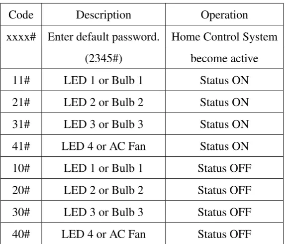
Table 1.1: User’s Home Control System Number Code
Code Description Operation
xxxx# Enter default password. Home Control System
(2345#) become active
11# LED 1 or Bulb 1 Status ON
21# LED 2 or Bulb 2 Status ON
31# LED 3 or Bulb 3 Status ON
41# LED 4 or AC Fan Status ON
10# LED 1 or Bulb 1 Status OFF
20# LED 2 or Bulb 2 Status OFF
30# LED 3 or Bulb 3 Status OFF
40# LED 4 or AC Fan Status OFF
For safety purpose, this system comes with a default password which is 2345.
After receiving the correct combination number only then the Home Control System
will become active. However, if the user want to change the combination number to
their preference, they can change it to other combination number which activate the
PROGRAM mode of the system.
The IC8880 also can transmit a signal to be used as an alarm system as it is
a transceiver. The limit switch will activate the alarm system and the microprocessor
will send the order to call the user phone. For doing so, user need to set the phone
number that the Home Control System will be alert to.
At the other end of the Home Control System is the Client Appliances Unit
which consists of four relays that each are connected together with the AC power
supply. It act as the switching device that are connected to normally open contact.
When the microcontroller giving the high input to the relays, the relays will be active
1.5 Report Structure
The structure of this report is divided into five main chapters excluding their subs.
There are Chapter I Introduction, Chapter II Literature Review, Chapter III Project
Methodology, Chapter IV Results and Discussion and Chapter V Conclusion and
Fu-ture Work.
Chapter I is as an Introduction of this report. This chapter acts as the first
acquaintance of this project that touch on the project overview, the objective of this
project, problem statement, and scope of work.
Chapter II is about the Literature Review which is an important part of this
project and the most crucial section of this report. It discuss on the previous work
that had been done in the same field. Literature review will covers on the reviewed
journals and also the components used in this project and some theory that required in
supporting the research of this project.
Chapter III is discuss on the Project Methodology. This chapter explain the
procedures that have been conducted in order to complete this project. It divided into
2 main subsection which is for the circuit design and program design. The process
of designing, fabrication, assembly, troubleshooting and making the final product is
discuss here. In order to make the user understand more about the process, a flowchart
are used to illustrate the process.
Chapter IV, Result and Discussion is about the analysis and the finding of this
project. The results from the project, is illustrated by using tables and pictures. This
chapter discuss and explain the design process and the finding between the expected
and actual result.
Chapter V is about the Conclusion and Future Work. Conclusion of this project
has been made due to overall project. This chapter also contain a recommendation for
7
CHAPTER 2
LITERATURE REVIEW
2.1 Introduction
This chapter will explain and discuss about the source and reference that related and
relevant to the project. Some research to gather on the basic working principle and
information from the previous related work had been done and been reviewed again in
this chapter. This is important chapter in order to make the project function as desired
at the end of the time.
2.2 History of Home Automation
Home automation has been around since the World War 1 (1914), in fact, the
wire-less remote control was first patent and unveiled by Nikola Tesla in 1898 when he
controlled a miniature boat by sending it radio waves [1]. Since then, after the second