STRESS DISTRIBUTION AROUND IMPLANT WITH
STRAIGHT AND ANGLED ABUTMENTS IN DIFFERENT
BONE QUALITIES.
Dissertation submitted to
THE TAMILNADU Dr.M.G.R.MEDICAL UNIVERSITY In partial fulfillment for Degree of
MASTER OF DENTAL SURGERY
BRANCH I
–
PROSTHETIC DENTISTRY INCLUDING
Raja Nagar, Kavalkinaru – 627105, Tirunelveli District
DCI Recognition No. DE-3 (44)-93/2246, Dated 09/11/1993 Affiliated to the Tamil Nadu Dr. M.G.R. Medical University, Chennai
DEPARTMENT OF PROSTHETIC DENTISTRY
INCLUDING CROWN AND BRIDGE AND IMPLANTOLOGY
CERTIFICATE
This is to certify that this dissertation entitled “THREE DIMENSIONAL
FINITE ELEMENT ANALYSIS OF STRESS DISTRIBUTION
AROUND IMPLANT WITH STRAIGHT AND ANGLED
ABUTMENTS IN DIFFERENT BONE QUALITIES.” is a genuine
work done by Dr. MAHESH B under my guidance during her post graduate
study period between 2009-2012.
This Dissertation is submitted to THE TAMILNADU Dr. M.G.R
MEDICAL UNIVERSTY, in partial fulfillment for the degree of MASTER
OF DENTAL SURGERY IN PROSTHETIC DENTISTRY
INCLUDING CROWN AND BRIDGE AND IMPLANTOLOGY -
BRANCH I. It has not been submitted (partial or full) for the award of any
other degree or diploma.
Date:
Place :
Dr.Suneetha .T.J, M.D.S
Head Of The Department
Department Of Prosthetic Dentistry
Including Crown And Bridge And Implantology Rajas Dental College And Hospital
I am sincerely grateful to Dr.Suneetha .T.J. , Professor and Head of the department for her encouragement, help, guidance, advice and care throughout the course of this study and my entire P.G curriculum.
I express my gratitude and thanks to Dr.Arunkumar.G., Professor and former Head of the department for his guidance, advice and help given to me in my thesis.
I wish to thank my principal Dr.Suresh Sathiyasekhar for the kind permission granted me for utilizing the college facilities.
I also express my thanks to Dr.Dadu George, Dr.Paulin Vijay Chandran, Dr.Appukannu, Dr.Arthi, Dr.Somasundaram, Dr.Lin Cherian Kovoor, Dr.T.C.Giri and Dr.Jude Sudhakar for their help and advice in the study.
I thank my colleagues Dr.Josna, Dr.Joephin Soundar, Dr.Madhu mahadevan, , Dr.Aneesh, and Dr.Jean for their help and support.
I thank our entire department staff for their timely assistance and help throughout the study.
I thank Mr.Sarnath and his assistants for their help and guidance in this study.
My sincere thanks to all those who have helped me directly and indirectly.
My heartfelt gratitude to my Mother, my wife and my son for their affection and support that gave me confidence throughout my course.
ABSTRACT
TITLE:Three dimensional finite element analysis of stress distribution around implant with straight and angled abutments in different bone qualities.
AIM:The aim of this study was to compare the stress distribution in different bone qualities of D1, D2, D3 & D4 with straight and angled abutments using Three Dimensional Finite Element analysis.
MATERIALS AND METHODS:A three dimensional finite element model of the premaxilla region and a solid 4.3 x 10 mm implant with a straight abutment (M1) and an angled abutment (M2) was done. Four distinctly different bone qualities of D1 ,D2 ,D3 & D4 were made. Simulated occlusal load of 178 N was applied at the centre of incisal edge along the long axis of each abutment. The maximum equivalent von Misses stress values around the implants were recorded.
RESULTS:The distribution of stresses changed considerably with abutment angulation. As angulation increased from 00 to 150 the concentration of von Mises stress shifted to the cortical layer of bone on the facial side of the fixture. In D1, D2, D3 & D4 bone qualities the highest von Mises stress values were obtained at the crestal region of implant. The maximum von Mises stress of 20.832 was recorded in D4 cortical bone on the buccal side of angled abutment.
CONTENTS
Page No
INTRODUCTION
1
AIMS OF THE STUDY
4
REVIEW OF LITERATURE
5
MATERIALS AND METHODS
32
RESULTS
43
DISCUSSION
51
CONCLUSION
59
FIGURES Page No
Figure 1: Maxilla Bone Model. 40
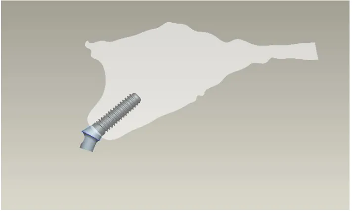
Figure 2: Maxilla Bone With Implant And
Angled Abutment 40
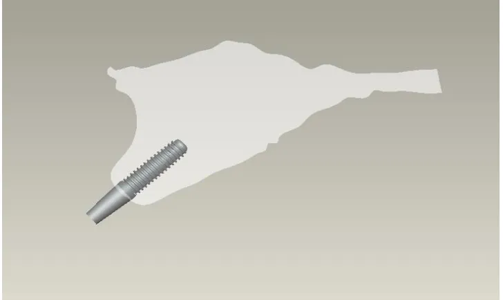
Figure 3: Maxilla Bone With Implant And
Straight Abutment 41
Figure 4: Meshed Model 41
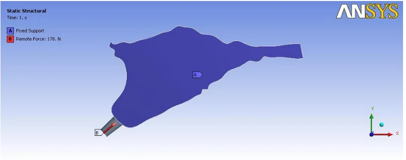
Figure 5: Loading Condition For Implant 42
And Angled Abutment
Figure 6: Loading Condition For Implant 42
And Straight Abutment
Figure 7: D1-Straight Abutment
D2 Straight Abutment 47
Figure 8: D3 Straight Abutment
D4 Straight Abutment 48
Figure 9: D1 Angled Abutment
D2 Angled Abutment 49
Figure10: D3 Angled Abutment
Bone around implant M1 45
Figure12: Bar diagram showing Stress values with in
TABLES
Page No
Table 1: Number Of Elements And Nodes 38.
Table 2: Material properties used in FEA study 39
Table 3: The value of von mises stress for the models
with straight abutment-MI 45
Table 4: The value of Von Mises Stress for the models
INTRODUCTION
Dental implants have been proven to be an effective way of restoring
the masticatory ability of completely or partially edentulous patients. The
desired position of the artificial teethis determined by esthetic and functional
requirements. Sufficient amount of bone for implant placement is an
essential pre requisite for the long term success in oral implant therapy.
The quantity of alveolar bone decreases after periodontal disease or after
extraction, causing bone loss in both horizontal and vertical direction.
Lack of horizontal bone volume always result in exposure of implant
surface, decreased bone- implant interface and finally implant failure. Lack of
bone volume is more common in the anterior maxilla. The long term
prognosis for implants in the maxilla is less secure than that of edentulous
mandible4. Following tooth extraction in the anterior part of the maxilla
horizontal bone resorption is almost twice as pronounced as vertical
resorption30.
This can be managed either by surgical correction or by positioning the
implant in the area with the greatest available bone with the intention of
correcting the implant alignment at the time of implant restoration. This is
Eger et al and Sethi et al concluded that angled abutments may be
considered a suitable restorative option when implants are not placed in ideal
axial positions15,14. The successful osseo integration of implant depends not
only on the bone quantity but also on the bone quality52.The classification
scheme for bone quality proposed by Lekholm and Zarb28 has been accepted
by clinicians and investigators as standard in evaluating patients for implant
placement. In this system, the sites are categorized in 1 to 4 groups on the
basis of jawbone quality.
In Type 1 (D1) bone quality, the entire jaw is comprised of homogenous
compact bone.
In Type 2 (D2) bone quality, a thick layer (2 mm) of compact bone surrounds
a core of dense trabecular bone.
In Type 3 (D3) bone quality, a thin layer (1 mm) of cortical bone surrounds a
core of dense trabecular bone of favorable strength.
In Type 4 (D4) bone quality, a thin layer (1 mm) of cortical bone surrounds a
core of low-density trabecular bone.
Implant manufacturers have introduced preangled abutments as a
prosthetic option for dentitions that are otherwise difficult to restore because
of implant locationor angulation. The angulation of these abutments varies
abutments and angled abutments showed that the bone loss or the survival rate
of angled abutments were not significantly different from straight
abutment10,14,20,46 .However the Strain gauge measurements and
Photoelasticmodels of Brosh et al12and the finite element analyses of Canay
et al 9and Clell and et al7revealed that angled abutment were subjected to
higher stress values around the cervical region than those observed for
straight abutment.
Few investigators have studied the unavoidable situation of placing and
loading implants at an angulation in the anterior maxilla, but they did not
consider the variation in bone qualities5,7 which may influence the stress
distribution around the implant with angled abutments. The purpose of the
present studyis to compare the stress distribution in various bone qualities of
D1,D2,D3 and D4 with straight and angled abutments using three
AIM
The aim of this study was to compare the stress distribution in different
bone qualities of D1,D2,D3 &D4 with straight and angled abutments using
REVIEW OF LITERATURE
Douglas Allen Atwood (1962)1stated that resorption of residual ridge is a
complex biophysical process. When force within certain physiologic limits
is applied to living bone, that force, whether compressive, tensile, or
shearing, brings about by some unknown mechanism the remodeling of the
bone through a combination of bone resorption and bone formation.
Bone resorption of residual ridges is a common occurrence after the
extraction of teeth. Both the total amount of bone loss and the rate of
resorption varied among different patients. In addition, the rate of
resorptionvaried for a given patient at different times.
Bo Rangert et al (1989)2stated that Two main types of loading of the
implants should be considered: (1) axial force and (2) bending force. Axial
forces are more favorable, because they distribute stress more evenly while
bending forces exert (unfavorable) stress gradients on the implant. If
loading of the fixtures mainly consists of bending moments, the
For well-integrated fixtures in bone of good quality, the weakest point in the
system will be the gold or abutment screw, which should be regarded as a
safety feature
Nancy .L. Clelland and Amos Gilat (1992)3compared the stress production
characteristics of five abutment angulations for a 3.75 x 10-mm Branemark
implant system. Each 4-mm abutment of 00,150, 250, and 350 angulation
was assembled on the fixture, subjected to 178N load, and viewed with a
circular polariscope. The authors concluded that stress distribution is more
favorable forabutments of less angulation. All of the five abutment
angulations investigated produced strains at the location of the rosettes that
were within the physiological zone for bone and higher stresses and strains
can beexpected closer to the fixture.
Charles .A. Babbush, Mari Shimura (1993)4evaluated patients who were
reconstructed with the IMZ system, which consists of a cylindrical implant
with anintramobile element for stress relief. It is placed through a two-stage
Implants in the maxilla had a lower survival rate than implants in the
mandible.
Nancy L. Clelland et al (1993)5conducted a study to determine the effect
of abutment angulation on the stress field near a specific dental implant.
Zero-degree, 15-degree, and 20-degee abutments were assembled on each of
the six 3.8× 10-mm Steri-Oss implants , subjected to 178 N load, and
viewed with a circular polariscope. As the abutment angle changed from 0
degrees to 20 degrees, compressive stress nearly doubled, and the changes
were statistically significant. Tensile stress increased with an increase in
abutment angulation, but the increase was only statistically significant
between 0 and 15 or 20 degrees.
Nancy L. Clelland et al (1995)6Analyzed the stresses and strains produced
by an abutment system of three abutment angulations by three-dimensional
finite element model of the maxilla. A simulated occlusal load of 178 N was
applied along the long axis of 00 ,150 and 200 abutments. Peak stresses were
located in the cortical bone, and the magnitude of these stresses increased
were within the physiological parameters described for animals with one
exception. Peak compressive stress for the 20O abutment was slightly above
this physiological zone, and this result suggests a need to evaluate greater
abutment angulations. Although strains were primarily situated in the
cancellous bone for all three cases, a more facial location was observed for
the 15O and 20Oangles.
Renato Celletti,Carneas.H. Pameijer (1995)7 studied the transmission of
masticatory forces on the bone by the use of preangled abutments on
implants. Nineteen endosseous implants were placed in two subhuman
primates. Then waiting period of six months were given to allow
osseointegration. The implants were fitted with Straight non segmented
abutment sand preangulated abutments of 25 and 35degrees. Clinical and
histological evaluation were done. His tologic evaluation revealed that
after 1 year the implants showed complete osseointegration. Implants
whether restored with straight or preangled abutments, had no adverse effect
on the surrounding bone. Loss of components were caused by mechanical
failure of abutment screws and did not affect the integrity of the implants.
unfavorable angles can be fitted with preangled abutments without
compromising esthetics and function.
G.Papavasiliou,P.Kamposiora,S.Bayne,D. A. Felton(1996)8investigated
clinical simulations involving single implants that were capable of creating
excessive stress at bone implant interface that exceeded elastic limit of
bone. Changing the veneering material on the prosthesis had no significant
effect on the stress levels or distribution at the bone-implant interface.
Oblique loads produced great increase over axial loading for stress levels
and distributions. Under axial loading, high resolved stresses were produced
on the occlusal third of the superstructure and low stresses were distributed
to the bone. The highest stresses were concentrated in the cortical bone.
Stresses under oblique loading were approximately10 times greater than
under axial loading.
Canay .S.etal (1996)9Analyzed the distribution of stress around implants
placed in the first molar region of the mandible biomechanically in a
two-dimensional mathematical model and found no measurable differences in
and angled implants. However, with the vertical loading, the compressive
stress values were five times higher around the cervical region of the angled
implant than around the same area in the vertical implant.
Thomas .J .Balshi et al( 1997)10 observed that from 3 year survival rates
study showed good preliminary results for angulated abutments compared to
standard straight abutments .Total percentage of implant loss in relation to
bone quality –Type- I, II, III, IV are the same as in standard abutments. The
study indicated that angulated abutments should be comparable to standard
straight abutments as a predictable modality in prosthetic rehabilitation.
RoxanaStegaroiu et al (1998)11 assessed stress in bone around titanium
implants using three treatment designs for a partially edentulous mandible,
under axial (AX), buccolingual (BL), or mesiodistal (MD) loads.
Model 1: Three implants supporting three connected crowns (M1) Model 2:
Two implants supporting a cantilever prosthesis (M2) Model 3: Two
implants supporting a conventional FPD (M3)For each of these loads,
highest stress was calculated in the model with a cantilever prosthesis
supported by two implants (M2). Less stress was found in the model with a
was calculated in the model with three connected crowns supported by three
implants (M1). When BL load was applied to conventional fixed partial
denture on two implants( M3), cortical bone stress was high, comparable to
that calculated for M2 under the same load.
Tamar Brosh, Raphael Pilo, and David Sudai (1998)12Studied the
influence of abutment angulation on strains and stresses along the implant
bone interface by using strain gauges attached to implants embedded in a
medium simulating bone and compared the results with photoelastic method
. Strain guage measurement showed that when the abutment angle was
increased from 0 to 15 degrees, 300% higher compressive strains were
measured, compared with the straight abutment. They concluded that
identical vertical loads applied on preangled abutments produced higher
stresses at the coronal zone of an implant compared with the straight
abutment.
Graziono.D. Giglio(1999)13described the process of selecting on abutment.
He stated that involves evaluating the position, angulation, interocclusal
space, and tissue height of a given implant. An angulation discrepancy
abutment. When using acementable restoration, the angulation is not as
critical since there is no screw-access opening. Angulated abutment replicas
(angulation guides) are commercially available in varying angulations and
tissue heights to help select the appropriate angulated abutment.
AshokSethi, ThomasKaus, Peter Sochor (2000)14presented preliminary
results of the clinical long-term behavior of implants restored using a broad
range of angulated abutments. These were observed over a period of up to
96 months, with a mean observation time of 28.8 months. With a certainty of
95%, an estimated mean survival rate better than 98.6% after a 5-year
observation period was calculated.
The results of this study demonstrated that there is no difference in the
survival of implants based on the use of angulated abutments ranging from 0
to 45 degrees and they can be used without compromising the long-term
survival of implants.
Dorothy E. Eger- (2000)15compared the survival of straight and angled
significant differences with respect to probingdepths, gingival inflammation
or attachment levels around straight or angled abutments. A comparison of
clinical and demographic variables, evaluated for implants restored with
angled and standard abutments, yielded no significant differences for any
parameter at any time period. They suggested that end osseous implants
placed at unfavorable angles may be restored with angled abutments without
compromise of function or esthetics.
John. B. Brunski(2000)16Stated that all oral and maxillofacial implants are
meant to support forces in vivo, so it is obvious that biomechanics plays a
major role in implant design. For lateral bite forces in the normal human
dentition, the data are less definitive. All implants will be exposed to intra
oral forces and moments and loads will be transmitted to interfacial tissues.
In the incisal region, the direction of maximum incisal bite force is about 12
degrees to the frontal plane, which suggests that the lateral components of
force on an anterior implant could be appreciable. They also stated that for
Biomechanical Models for Predicting Implant Loading 3-dimensional FEA
models are more advantageous than strain-gauged abutments and
David .G. Gratton et al (2001)17 Investigated dental implant screw joint
micromotion and dynamic fatigue as a function of varied preload torque
applied to abutment screws when tested under simulated clinical loading.
The results of the study revealed that under the loading parameters of this
study, no measurable fatigue of the implant– abutment interface occurred.
However, dental implant screw joints tightened to lower preload values
exhibited significantly greater micromotion at the implant–abutment
interface.
Jian-Ping Geng et al (2001)18Reviewed the current status of FEA
applications in implant dentistry and discusses findings from FEA studies in
relation to the bone–implant interface, the implant–prosthesis connection,
and multiple-implant prostheses They stated that key factor for the success
or failure of a dental implant is the manner in which stresses are transferred
to the surrounding bone. Factors that influence load transfer at the bone–
implant interface include the type of loading, implant and prosthesis material
properties, implant length and diameter, implant shape, structure of the
implant surface, nature of the bone–implant interface, and the quality and
Estevam B. et al (2002)19Compared the Stress Distribution between Angled
And Vertical Implants and saw that Stresses in the angled implant were
higher than in vertical model. The larger differences in stresses were for
vertical loading, reaching 25%for peak compressive stresses. Much higher
stress values as expected occurred under horizontal loading, for both
designs. It should be noted that in normal function, during mastication, the
vertical components of the loading are significantly higher than the
horizontal components.
Ashok sethi et al (2002)20Described the evolution of the concept of
selecting the abutment at first-stage surgery and presents clinical data
accumulated over 14 years of the use of this concept with angulated
abutments. Good esthetic and functional outcomes were achieved by the use
of conventional cement-retained restorations made possible by parallel and
aligned abutments. Over 10 years, the angulation had no effect on the
Tada.S.et al (2003)21 Performed a 3-dimensional finite element analysis to
evaluate the influence of implant type and length, as well as that of bone
quality, on the stress/strain in bone and implant. Axial and buccolingual
forces were applied to the occlusal node at the center of the abutment.
Regardless of load direction, maximum equivalent stress/strain in bone
increased with a decrease in cancellous bone density. Under axial load,
especially in the low-density bone models, maximum equivalent strain in
cancellous bone was lower with the screw-type implant than with the
cylinder- type implant.
Murat Sutpideler.M, etal (2004)22 conducted finite element analysis to
determine the stress in the supporting bone when implants were arranged in
either a straight-line or an offset configuration and assessed the effects of
axial and nonaxial loading and changes in prosthesis height .Vertical loading
of an implant-supported prosthesis produced the lowest stress to the
supporting bone. Changes in the angle of force application resulted in
greater stress to supporting bone. Reduction in prosthesis height or use of an
offset implant location for the middle implant reduced stress, but the
Murat Cehreli et al (2004)23Compared stress and strain magnitudes of
butt-joint and internal-cone oral implants in a bone stimulant through
photoelastic and strain-gauge analysis and found out that Butt-joint and
internal-cone oral implants have similar force distribution characteristics.
They concluded that the implant–abutment mating design is not a decisive
factor affecting stress and strain magnitudes in a bone simulant.
Murat cavitCehreli et al (2004)24Compared force transmission behaviors of
one-piece (1-P) and two-piece (2-P) morse-taper oral implants by
three-dimensional finite element analysis. Von Mises stresses in the implant,
principal stresses, and displacements in the resin were the same for both
designs under vertical loading. Under oblique loading, principal stresses and
displacement values in the resin were the same, but the magnitudes of von
Mises stresses were higher in the piece implants They concluded that
2-piece implants experience higher mechanical stress under oblique loading.
Lucie Himmlova,T(2004)25 stated that an increase in the implant diameter
decreased the maximum von Mises equivalent stress around the implant
favorable distribution of the simulated masticatory forces applied in this
study.
Eriko Kitamura et al (2004)26 performed a three-dimensional finite element
analysis of the influence of marginal bone resorption amount and shape on
stress in the bone and implant was investigated. The results of this analysis
suggest that a certain amount of conical resorption may be the result of
biomechanical adaptation of bone to stress. However, as bone resorption
progresses, the increasing stresses in the cancellous bone and implant under
lateral load may result in implant failure.
E Kitamura et al (2005)27performed a three-dimensional finite element
analysis to compare the bone stresses in a non-resorption model with those
in four models with bone resorption of two depths (1·3 and 2·6 mm) and
types (horizontal resorption and angular defects). Axial and bucco-lingual
forces were separately applied to the center of the superstructure and the
stress (highest stress concentration around implant neck, higher stresses
under bucco-lingual than axial load, as well as in the cortical than cancellous
bone) were the same in the non-resorption and resorption models. Bone
stress distributions were similar in the non-resorption and horizontal
resorption models, but differed from those in the angular defect models.
Moreover, the changes of the bone stress values with resorption depth
differed for the two resorption types. Thus, in FEA, accurate simulation of
the marginal bone shape in the implant neck region is advisable.
M. Sevimay et al (2005)28studied the effect of 4 different bone qualities on
stress distribution in an implant-supported crown, using 3-Dfinite element
(FE) analysis and observed that von Mises stresses in D3 and D4 bone
qualities reached the highest values at the neck of the implant and were
distributed locally. A more homogenous stress distribution was seen in the
entire bone for bone groups D1 and D2, and a similar stress distribution was
observed. Because the trabecular bone was weaker and less resistant to
deformation than the other bone qualities modeled, the stress magnitudes
DING Xi et al (2005) 29Applied three-dimensional finite element method
to analyze the influence of various angled abutments on the distribution of
the stress and strain in the implant-bone interface. Results showed that Von
Mises stress occurred predominantly in the cortical bone layer-on the neck
of implants. There was an increase occurred in the magnitude of stress and
strain in the implant-bone interface as the abutment angulation increased. It
increased obviously when the implant was connected by 30° abutment.
S. Jivraj ,W. Chee and P. Corrado(2006)30 describes about the treatment
plan in edentulous maxilla and stated that upon consideration of bone
quantity, bone quality, resorptive patterns and maxilla mandibular
relationship it usually becomes apparent that the actual amount of bone
available for placement of implants in the maxilla may not only be limited
but may also be present in areas remote from the original site of the natural
teeth. In the pre maxilla the tooth position may be much further forward than
the implant position and this may pose certain biomechanical disadvantages.
So following the same prosthetic concepts forthe maxilla as existed in the
mandible is notfeasible. The long term prognosis for implants in the maxilla
type 3 or type 4 bone quality is often found. This quality of bone often
dictates over engineering at time of implant placement.
Chun H.J. et al (2006)31investigatedthe effect of abutment type on stress
distribution in bone under vertical and inclined loads by FEA with contact
friction interface between abutments and three type implant system- one
piece implant, internal hex and external hex. Maximum von Mises Stress
occurred at the region of compact bone adjacent to the first implant
microthead of all implant system with different abutments for both vertical
and inclined loading. It was concluded that the abutment type has
significant influence on stress distribution in bone because of different load
transfer mechanism and difference in size of contact area between the
abutment and the implant.
Flemming Isidor et al (2006)32reviewed the relationship between forces on
oral implants and the surrounding bone. Occlusal forces affect an oral
implant and the surrounding bone. Bones carrying mechanical loads adapt
their strength to the load applied on it by bone modeling/remodeling. This
also applies to bone surrounding an oral implant. The response to an
of the bone by increasing the bone density or apposition of bone. On the
other hand, fatigue micro-damage resulting in bone resorption may be the
result of mechanical stress beyond this threshold In clinical studies an
association between the loading conditions and marginal bone loss around
oral implants or complete loss of osseointegration has been stated, but a
causative relationship has not been shown.
Xavier E Zaab (2007)33measured and compared the strain distribution on
the bone around an implant in the anterior maxilla using different abutments
by means of finite element analysis. The greatest strain was found on the
cancellous bone, adjacent to the 3 most apical microthreads on the palatal
side of the implant where tensile forces were created.
The same strain distribution was observed around both the straight and
angled abutments. The model predicted a 15% higher maximum bone strain
for the straight abutment compared with the angled abutment
G. Dubois, M. Daas A.S. Bonnet , P. Lipinski (2007)34studied the complex
behaviour of an upper lateral incisor restoration using an angled abutment,
carried out by Finite Element Analysis . The authors concluded that the
abutment studied could safely be used, in the case of an upper lateral incisor
restoration, for a range of external forces included between 0 and 280 N. No
yielding was observed in this situation. However, if this angled abutment
was used for a molar restoration, a risk of damage would exist as the forces
applied may exceed 300 N because it generated bending stresses inside bone
and implant.
Jose Henrique Rubo, Edson Antonio CapelloSouza(2008)35Studied the
stress distribution in bone adjacent to dental implants by means of FEA.
They stated that the load transfer is dependent upon the occlusal loads,
implant shape and size, biomaterial properties, density of bone, and nature
of the interface. The presence of a stiffer cancellous bone has the benefit of
reducing the stress where it reaches its peak, namely the cervical area around
the terminal abutment. At the same time, the stress in cancellous bone
somehow increases, balancing the stress distribution. The findings of this
study have shown that varying the height of the abutments will have a
Kao.H.C etal(2008)36investigated the micromotion between the implant
and surrounding bone caused by the use of an angled abutment for an
immediately loaded single dental implant located in the anterior maxilla.
The micromotion between the bone-implant interfaces was calculated using
ANSYS software. The micromotion values for 15-degree and 25-degree
angled abutments were 119% and 134%, respectively, compared to the
corresponding values for straight abutments. Compared to straight
abutments, the 25-degree abutments resulted in increased maximum von
Mises stresses to a level of 18%.Most of the stresses were concentrated
within the cortical bone around the neck of the implants. The authors
concluded that , abutment angulation up to 25 degrees can increase the stress
in the peri-implant bone by 18% and the micromotion level by 30%.
Baggi L et al (2008)37analysed the influence of implant diameter and length
on stress distribution and to analyze overload risk of clinically evidenced
crestalbone loss at the implant neck in mandibular and maxillary molar
periimplant regions. Maximum stress areas were numerically located at the
implant neck, and possible overloading could occur in compression in
at the interface between cortical and trabecular bone (due to vertical
intrusive loading components). Stress values and concentration areas
decreased for cortical bone when implant diameter increased, whereas more
effective stress distributions for cancellous bone were experienced with
increasing implant length. For implants with comparable diameter and
length, compressive stress values at cortical bone were reduced when low
crestal bone loss was considered.
Quaresma S.E. et al (2008) 38 evaluated the influence of two commercially
available dental implant systems on stress distribution in the prosthesis,
abutment, implant, and supporting alveolar bone under simulated occlusal
forces, employing a finite element analysis. The stepped cylinder implant
connected to a screw-retained, internal hexagonal abutment produces greater
stresses on the alveolar bone and prosthesis and lower stresses on the
abutment complex. In contrast, the conical implant connected to a solid,
internal, conical abutment furnishes lower stresses on the alveolar bone and
Georges Tawil (2008) 39Reported that the stability of peri implant tissue is a
balance between functional forces and reaction of supporting structures.
Bone remodeling can be a possitive expression in response to mechanical
stimulation. He stated that increased marginal bone loss can be either due to
adaptation of function or due to increased occlusal overload.
Lin CL et al(2008)40studied the biomechanical response of implant system
placed in the maxillary posterior region under various conditions of
angulation, bone density and loading under finite element analysis. The
result data for maximum von Mises stress for angled abutment was more
than the straignt one. They also noted that implant and cortical bone strain
was higher for an angled abutment of 20° than that for straight abutments
and that bone strain increased as bone density decreased.
Golvani. E. Salvi (2009)41 appraised the impact of mechanical and technical
risk factors on implant-supported reconstruction by comparing the literature
reviews and articles. The presence of angled or angulated abutments was not
associated with increased mechanical or technical risks for
angled abutments, the crown-implant ratio, and the number of implants
supporting fixed dental prosthesis were not associated with increased
mechanical or technical complications. None of the mechanical or technical
risk factors had an impact on implant survival and success rates.
Chun-Li Lin et al (2009)42Investigated the interaction of implant position,
implant abutment connection and loading condition influencing boneloss of
an implant placed in the maxilla using finite element analysis. It was found
that buccal site suffered the most bone loss around the implant, followed by
distal, lingual and mesial sites. The implant position primarily influenced
bone loss and it was found most obviously at the buccal site. Abutments of
internal engagement with or without taper-fit did not affect the bone loss in
the surrounding bone.
Ting Wua et al (2010)43 Studied the biomechanical behavior of
Computer-aided design/computer-aided manufacturing (CAD/CAM) custom
abutments. Simulation results indicated that there was no distinct difference
in the stress distribution and magnitude of implant-bone interface and screw
Takeshi Takahashi et al (2010)44performed Three-dimensional finite
element analysis to clarify differences in stress in peri-implant cortical bone
between 6implants and 4 implants with change in inclination angle based
on the All-on-4 Concept. They found that stress was concentrated around
the posterior-most implant and the stress increased with 4 implants and
increase in angulation. The use of 4 implants or inclined implants increased
stress on peri-implant cortical bone. However, when used in conjunction
with ashort cantilever, inclined implants decreased stress on peri-implant
cortical bone.
Chun.yeoHa etal (2011)45 studied the influence of abutment angulation on
screw loosening of implants in the anterior maxilla. They found that the
angled abutment group showed significantly higher removal torque values
(RTV’s) than straight abutments in external hex implants. However no
significant difference in RTV was found among abutments in internal hex
John Cavallaro, Jr. and Gary Greenstein (2011)46 searched the dental
literature for clinical trials that appraised the survival rate and complications
(biological and technical) associated with pros-theses that are supported by
angled abutments. The results of photoelastic stress assessments, finite
element analysis and strain-gauge studies indicated that increased abutment
angulations result in the placement of a greater amount of stress on
prostheses and the surrounding bone than that associated with straight
abutments. However, survival studies did not demonstrate a significant
decrease of prostheses’ longevity associated with angled abutments.
Furthermore, there was no additional bone loss adjacent to implants that
supported angled abutments compared with straight abutments, and angled
abutments did not manifest an increased incidence of screw loosening. On
the basis of the available data in literature, the authors concluded that angled
abutments result in increased stress on the implants and adjacent bone.
These increased stresses usually are within physiological tolerances.
Use of angled abutments has not decreased the survival rate of implants or
prostheses in comparison with that of straight abutments, nor has the use
Istibrak Hassan etal (2011)47investigated the influence of abutment design
on bone resorption around immediately loaded and osseointegrated
implants and found significant difference between non and submerged
implants with angled abutment and between the submerged implants with
straight and angled abutments. No significant difference were observed
between non and submerged implants with straight abutments and between
non submerged implants with straight and angled abutments. They
concluded that bone resorption around dental implants is influenced by the
abutment design and implantation protocol.
Ellakwa , Raj, Deeb. S. ,Ronaghi. G(2011)48 Performed an in vitro study to
assess the effect of three implant abutment angulations and three core
thicknesses on the fracture resistance of overlaying computer-aided
manufacturing (CAM) milled zirconia single crowns. Implant abutment
angulations significantly reduced the fracture resistance of overlaying
CAM-milled zirconia single crowns. The fracture loads of crowns cemented onto
tested. Reducing the core thickness from 0.8 mm to 0.4 mm did not affect
the fracture resistance of overlaying CAM-milled zirconia single crowns.
JianpingGeng, W eiqi Yan, WeiXu49 Application of the Finite Element
Method in Implant Dentistry- Zhejiang University Press, Hangzhou and
Materials And
MATERIALS AND METHODS
A three dimensional finite element model of premaxilla was created
using a computerized tomography image. The scanned image was entered
into a computer software program. Cross-sections were reassembled to get
the three dimensional model of the premaxilla. Four distinctly different bone
qualities of D1,D2,D3&D4 were made. A solid 4.3 mm x 10 mm screw type
commercially pure titanium implant (Nobel Biocare, Goteborg, Sweden )
with a straight abutment and an angled abutment was placed in the central
incisor region. Three dimensional finite element model were constructed for
the following configurations.
M1- an implant with astraight abutment(00).
M2- animplant with an angledabutment (150).
Each of these implants were placed in four premaxilla models of distinctly
different bone qualities D1,D2,D3 and D4 respectively.
Abutments have a basediameter equal to implant diameter of 4.3 mm
with occlusal taper. Apart from the different angulations the 7-mm
abutments were identical.
Finite element models were simulated using Pro-engineering wild fire
The analysiswas performed using the software ANSYS Workbench
10.0.The models were processed in ANSYS to generate a meshed
structure(Figures -1,2,3,4). Meshing divides the entire model into smaller
elements which are interconnected at specific joints called nodes. The
numberof elements and nodes used for each model is shown in Table I.
In the current study, the materials used for the models were
presumedto be isotropic and the osseointegration of implant was accepted as
100%. The material properties were determined from values obtained
fromthe literature51( Table II) .A simulated occlusal load of178 N was
applied at the centre of incisal edge along the long axis of each abutment
(Figures- 5,6) . The amount of the load selected was based on the published
average biting forces for incisor 33,7,50. The applied forces were static.The
maximum equivalent von Mises stress values around the implants were
recorded .
The von Mises stresses are most commonly reported in finiteelement
analysis studies to summarize the overall stress stateat a point . All
materials were presumed to be linear, elastic, homogenous, and isotropic.
Most Finite Element analysis studies in the literature have modeled cortical
BASIC CONCEPT OF FINITE ELEMENT ANALYSIS
Finite element analysis (FEA)was initially developed in the early
1960s to solve structural problems in the aerospace industry. In 1977,
Weinstein was the first to use FEA in implant dentistry. Subsequently, FEA
was rapidly applied in many aspects of implant dentistry 18,49 .
FEA is a technique for obtaining a solution to a complex mechanical
problem by dividing the problem domain into a collection of much smaller
and simpler domains (elements) where field variables can be interpolated
using shape functions.
FEA is a method whereby, instead of seeking a solution function for
the entire domain, it formulates solution functions for each finite element
and combines them properly to obtain a solution to the whole body. The
finite element method provides a unique way of determining stress and
displacements because of its ability to model geometrically complex
structures. A computer simulated model is analysed to a numerical and
graphical solution.In the finite element method the complex structure is
divided in to smaller sub divisions called elements. The elements are
interconnected at specific joints called nodes.
The whole collection of elements and nodes is called a mesh. A mesh
Meshing divides the entire model in to smaller elements.(
Figure:4).With the incorporation of mechanical properties the structure
simulate the normal model. The nodes lie on the element boundaries where
adjacent elements are connected. Once meshing and contacts are defined the
next process is to define boundaryconditions.The process of creating the
mesh, elements, their respective nodes, and defining boundary conditions is
termed "discretization"of the problem domain. After defining the boundary
of the model, the loads to be applied are defined. Once the loads are
defined(Figures :5&6) the problem is solved by incorporation of the
material property (table-II) and the results can be reviewed.
Fundamentals of Dental Implant Biomechanics in FEA
Since the components in a dental implant-bone system is an extremely
complex geometry, FEA has been viewed as the most suitable tool to
mathematically, model it by numerous scholars18.In the past 2 decades, finite
element analysis (FEA) has become an increasingly useful tool for the
prediction of the effects of stress on the implant and its surrounding
bone49.Implant dentistry would greatly profit if it were provided the means
to predict how bone and implant components would behave considering
exerted on the prosthesis, etc. Finite-element analysis, with all its inherent
limitations, is a valuable instrument in pursuing that goal. The Finite element
method has some distinct advantages over the other methods of stress
analysis;
1- The technique is non-invasive
2- The tooth, the alveolar bone , implant can be simulated and when the
material properties of these structures are assigned, it is the nearest
that one can possibly get in simulating the oral environ ment in vitro.
3- The actual stress experienced at any point can be measured.
4- The actual displacement of the implant can be visualized graphically.
5- Reproducibility does not affect physical properties of the involved
material and study can be repeated any number of time.
Recently, with the development of digital imaging techniques, more efficient
methods are available for the development of anatomically accurate models.
These include the application of specialized softwares for the direct
transformation of 2D or 3D information in image data from CT or MRI, into
FEA meshes. The automated inclusion of some material properties from
measured bone density values is also possible. This will allow more precise
ARMAMENTARIUM
INTEL CORE 2 DUO PROCESSOR
2GB RAM
160 GB HDD
52X CD ROM
1.44 FDD
15”COLOUR MONITOR
PRO-ENGINEERING WILD FIRE SOFTWARE
ANSYS WORKBENCH 10.0 FINITE ELEMENT SOFTWARE
KEY BOARD
Table I: number of elements and nodes
STRAIGHT ABUTMENT ANGLED ABUTMENT
BONE NODES ELEMENTS BONE NODES ELEMENTS
D1 30243 16820 D1 30180 16720
D2 39143 23383 D2 39564 21066
D3 38908 20878 D3 38338 20452
Table2: Material properties used in FEA study
Material
Youngs
modulus (GPa)
Poisons ratio
Titanium abutment & implant 110 0.35
Dense treabecular bone
(D1 D2 & D3)
1.37 0.3
Low density trabecular bone
(D4 Bone)
1.10 0.3
Figure:1 Maxilla Bone Model
[image:52.612.137.493.478.692.2]Figure :3 Maxilla Bone With Implant and Straight Abutment
[image:53.612.133.491.491.656.2]Figure: 5 Loading condition for implant and angled abutment
[image:54.612.103.513.500.662.2]Results and
RESULTS
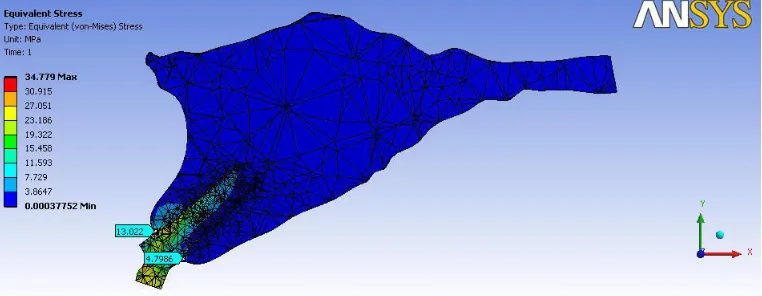
Stress distribution was represented numerically and was colour coded.
The von Mises stress for the straight abutment showed almost even
distribution of stress in buccal and lingual side of both cortical and
cancellous bone. The distribution of stresses changed considerably with the
abutment angulation. As the angulation increased from 00 to 150the
concentration of von Mises stresses shifted to the cortical layer of bone on
the facial side of fixture(Table III & IV ). The von mises stress around
M1and M2 was higher in cortical bone 3.66-20.832 than in cancellous bone
0.124 -2.0971.
In D1,D2,D3,&D4 bone qualities the highest von Mises stress values
were obtained at the crestalregion of the implant( Figures- 7, 8, 9, 10 ).
The von Mises stress on the buccal side of cortical bone in M1and M2
increased in magnitude as the bone quality differed from D1toD4. In all the
four bone types the stress values in cortical and cancellous bone on the
buccal side of M2 was found to be higher than the stress values on the
buccal side of M1. The maximum von Mises stress of 20.832 was recorded
The stress values were found to be lower on the lingual side of
implant with angled abutment in D2, D3, D4 bone types, when compared to
the implant with straight abutment. The increase in stress in the
buccalcortical bone when angled abutment as used was greatest for D4 bone
TABLE-3
The value of von mises stress for the models with straight abutment-MI
Bone quality Buccal Lingual
Cortical Cancellous Cortical Cancellous
D1 4.0965 3.662
D2 9.571 0.7787 7.551 1.068
D3 13.223 1.894 13.311 1.876
D4 15.444 1.1172 15.336 1.110
Figure – 11
Bar diagram showing Stress values with in Bone around implant M1
4.0965 3.662 9.571 0.7787 7.551 1.068 13.223 1.894 13.311 1.876 15.444 1.1172 15.336 1.11 0 2 4 6 8 10 12 14 16 18
Cortical Cancellous Cortical Cancellous
D1 D2 D3 D4
[image:58.612.115.536.514.719.2]TABLE- 4
The value of Von Mises Stress for the models with angled abutmentsmM2
Bone quality Buccal Lingual
Cortical Cancellous Cortical Cancellous
D1 13.022 4.798
D2 13.999 1.6299 2.563 0.2360
D3 19.261 2.0971 2.538 0.1599
D4 20.832 1.856 2.138 0.1242
Figure – 12
Bar diagram showing Stress values with in Bone around implant M2
13.022 4.798 13.999 1.6299 2.563 0.236 19.261 2.0971 2.538 0.1599 20.832 1.856 2.138 0.1242 0 5 10 15 20 25
Cortical Cancellous Cortical Cancellous
D1 D2 D3 D4
[image:59.612.115.521.492.700.2]Figure:7 D1-STRAIGHT ABUTMENT
Figure:8 D3 STRAIGHT ABUTMENT
Figure:9 D1 ANGLED ABUTMENT
Figure:10 D3 ANGLED ABUTMENT
DISCUSSION
The pattern of bone loss cannot be accurately predicted when teeth are
lost in the anterior maxilla 1.Lower survival rates were observed for implants
placed in the anterior maxilla than the anterior mandible4. Lack of bone
volume is more common in the anterior maxilla. The long term prognosis for
implants inthe maxilla is less secure than that of the edentulous mandible.
Following tooth extraction inthe anterior part of the maxilla horizontal
bone resorption is almost twice as pronounced as vertical resorption30 . This
change in bone morphology often dictates placement of implants with the
long axis in different and exaggerated angulations. The implant alignment is
corrected at the time of restoration with the use of angled abutment. A
variety of preangled abutments are available at specified divergence angles.
Additionally, custom angled abutments may be cast to the profile necessary
for an acceptable prosthetic outcome .
Studies on the biomechanical behavior of implants have concluded
that the major concentration of stresses at the implant bone interface usually
occurs at the crestal bone level8 ,29, 35, 36, 40 .
Crestal bone loss and early implant failure after loading results most
explained by the evaluation offinite element analysis of stress contours in
the bone5, 7,8,12, 33, 36,40,45.In the present study also the maximum von Mises
stress values were found at the crestal bone in all the four bone qualities .
The anteriorteeth were subjected to maximum compressive stress
duringincising and the force would be directed along the long axis of the
tooth. In implant with straight abutment the force is directed along the long
axis of the abutment and this results in the even distribution of stresses on
the buccal and lingual side in all the four bone qualities.
In angled abutment the force will be directed to the area of bone
opposite to that of crown inclination . In the present study the results shows
that the stress values on the buccal bone was found to be higher when the
abutment was inclined 15degree palatally. This leads to the inference that if
a case is planned for angled abutment, sufficient thickness of bone should be
available on the site opposite to that of abutment inclination to withstand the
extra stresses.
The stress values around M1and M2 were found to be more at the
cortical bone region than in cancellousbone. This is likely due to the
Cortical bone having a higher modulus of elasticity is more resistant to
deformation and will bear more load than cancellous bone. A finite element
analysis study by Jose Henrique Rubo35showed that stresses tended to be
concentrated at the cortical bone around the neck of the implant closest to
the load, whereas stresses in cancellous bone were considered low. The
mechanical stress distribution occurs primarily where bone is in contact with
the implant. The density of bone is related directly to the amount of implant
to bone contact. The percentage of bone contact is significantly greater in
cortical bone than cancellous bone.
The increase in stress values from D1 to D4 cortical bone may be due
to the fact that D1 bone is comprised of entire cortical bone andwas able to
distribute the stress evenly, whereas in D4 bone there was only a thin layer
of cortical bone, stresses were principally concentrated in the compact bone,
so the stress concentration per area will be more.
Although von Mises stress increased in straight abutment as the bone
quality changed from D1 to D4, it was more noticeable under the loading
side of the angulated abutments.
There is more increase in the stress concentration in the cervical zone
unfavorable loading direction that angled abutments have, it is important to
understand the stresses transferred through various abutment angulations to
the surrounding bone, through which we can prevent less than ideal stress
transfer conditions16,2.
Implant dentistry would greatly benefit if it were provided the means
to predict how bone and implant components would behave considering
each patient’s unique jaw anatomy, quality of bone, amount of occlusal force
exerted on the prosthesis, angulation of abutment etc. Finite element
analysis, with all its inherent limitations, is a valuable instrument in pursuing
that goal18.
Other types of failures related to angled abutments in reviewed
articles included fracture of the occlusal material14,fracture in parts of the
Framework14 , loosening or fracture of abutment screws20and loss of
osseointegration15 .
Most of the articles claiming high success/survival rates did not take
abutment screw loosening, occlusal material, or framework fracture into
account in calculating the success/survival rates. These complicationsmight
not eventually lead to implant failure, but can still be major concerns from a
In a study Clelland and colleagues7 , used a three dimensional finite
element model of the maxilla and confirmed that stresses and strains
became larger as abutment angles increased. In another study by Ding xi and
colleagues 29on the influence of various angled abutments on the
distribution of the stress and strain in the implant-bone interface, revealed
that von Mises stress occurred predominantly in the cortical bone layer on
the neck of implants.
Results of finite element analysis done by Kao and colleagues 36on the
influence of abutment angulation on micromotion level for immediately
loaded dental implants showed that most of the stresses were concentrated
within the cortical bone around the neck of the implants. The authors
concluded that abutment angulation up to 25 degrees can increase the stress
in the periimplant bone by 18% and the micromotion level by 30%.
Lin and colleagues 40 who conducted an analysis of stress on single
implants, also noted that the strains on the implant and cortical bone was
higher for an angled abutment of 20° than that of straight abutments and
The high stress concentration found around the coronal zone of the
implant should be considered. Clinical studies show that bone resorption
occurs around the coronal zone of the implant39.
In finite element analysis studies, the assumptions made regarding the
geometry, mechanical properties of the materials, and loads and constraints
applied to the model have a key role in the accuracy of the experiment49.
Clelland et al7created a 3-dimensional model of the anterior maxilla with a
1.5- and 3.0-mm-thick cortical layer with isotropic characteristics, which
does not represent type 3 bone with a thin cortical layer.
In the current study, all of the bone for the D1 bone model was
modelledas compact bone. Consequently the stress distribution was more
uniform and von Mises stresses were of a lower magnitude in straight
abutment in buccaland lingual side , whereas the von Mises stress was
concentrated in more magnitude in buccal side of the angled abutment than
the lingual side. So as angulation is increased from 00 to 150 the
concentration of compressive stresses shifted to the cortical layer of bone on
the facial side of the fixture.
For theD2 bone model, the elastic modulus of the central core of bone
available volume of compact bone was less than D1 bone quality. It was
almost equally distributed in both buccal and lingual side of D2 bone
(9.573& 7.551), whereas in the case of angled abutment there was a
prominent difference in readings of stress in both buccal and lingual (13.99
& 2.563).
In the D3 bone model, the thickness of the cortical shell was reduced.
Stresses were principally concentrated in the compact bone, and again, the
available volume of compact bone was less than for both D1 and D2 bone
qualities. The von Mises stresses were higher than D1 and D2 bone
qualities. This was more in angled abutment (19.261) compared to straight
(13.223).
The D4 bone model had the same cortical bone configuration as for
D3 bone quality; the only difference between these two models was in the
elastic modulus specified for the central core of bone ( table-II).The
low-density trabecular bone was modeled for D4 bone quality. Stress
concentrations in compact bone showed the same distribution as in the D3
bone model, but the von Mises stress values were greatest for D4 bone
Although von Mises stress increased in straight abutment as the bone
quality changed from D1 to D4 it was more noticeable under the loading
side of the angulated abutments. There is more increase in the stress
concentration in the cervical zone of the angled abutment when compared
CONCLUSION
Stress values concentration areas decreased for cortical bone when
straight abutments were placed over the implant, whereas more stress
distributions were seen for cortical and cancellous bone with angled
abutments placed over the implant. So the high stresses induced through
preangled abutments at the cervical zone of the implant due to forces and
moments could be a dominant factor that may aggravate the periimplant
bone loss or may change the existing peri-implantitis direction. An
alternative treatment plan, such as inserting the implant in perfect alignment,
concomitant with autogenous bone graft and membrane should be
considered to minimize the use of preangled abutments and to avoid the
BIBLOGRAPHY
1.Douglas Allen Atwood.Some Clinical Factors Related To Rate Of
Resorption Of Residual Ridges–J. Prosthet Dent . 1962;12(3): 441-450.
2.B. Rangert, ,TorstenJ,Forces and Moments on Branemark Implants-
Int J Oral Maxillofacial Implants1989; 4: 241-247.
3. Nancy. L. Clelland and Amos Gilat,The Effect of Abutment angulation
ons tress transfer for an Implant ,Journal ofProsthodontics 1992; 1(1):24-25
4.A.Babbush, Mari Shimura, Five-Year Statistical and Clinical
Observations With IMZ Two-Stage Osteointegrated Implant System
Int J Oral Maxillofac Implants 1993;8 (2): 245-253
5. Nancy L. Clelland, Amos Gilat, Edwin A. McGlumphy, William A.
Brantley A Photoelastic and Strain Gauge Analysis of Angled Abutments for