University of Southern Queensland Faculty of Health, Engineering and Sciences
Robot Cat – A free-fall analyses
A dissertation submitted by
Bernard Monz
in fulfilment of the requirements of
ENG4111 and 4112 Research Project
towards the degree of
Bachelor of Engineering (Honours) (Mechanical)
University of Southern Queensland Faculty of Health, Engineering and Sciences
ENG4111 & ENG4112 Research Project
Limitations of Use
The Council of the University of Southern Queensland, its Faculty of Health, Engineering and Sciences, and the staff of the University of Southern Queensland, do not accept any responsibility for the truth, accuracy or completeness of material contained within or associated with this dissertation.
Persons using all or any part of this material do so at their own risk, and not at the risk of the Council of the University of Southern Queensland, its Faculty of Health, Engineering and Sciences or the staff of the University of Southern Queensland.
Certification
I certify that the ideas, designs and experimental work, results, analyses and conclusions set out in this dissertation are entirely my own effort, except where otherwise indicated and acknowledged.
I further certify that the work is original and has not been previously submitted for assessment in any other course or institution, except where specifically stated.
Bernard Monz
Acknowledgements
The following people assisted with this project. I thank them for their time, guidance and patience.
• Mr Chris Snook – Supervisor / Lecturer / Examiner – Thank you for your guidance and answering my questions, as well as the time it will take to mark the assignments.
• Mr Terry Byrne – Coordinating Technical Officer – Thank you for the advise with printing the components, and driving the motors.
• Mr Graham Holmes – Senior Technical Officer – Thank you for advise with printing the components.
• Dr Tobias Low – Lecturer – Thank you for the assistance with the stepper motors.
• David Buttsworth – Professor – Suggestions on testing the robot.
Table of Contents
1 ABSTRACT...13
2 LIST OF FIGURES...14
3 LIST OF TABLES...15
4 NOMENCLATURE...16
5 GLOSSARY...17
6 PROJECT IDEA...18
6.1 A Brief Introduction...18
6.2 Idea Initiation...19
7 IDEA DEVELOPMENT...21
7.1 Gathering of Information (Literature Review)...21
7.1.1 Movement of cat in free fall...21
7.1.1.1 Tin-Can-Turn...21
7.1.1.2 Gauge Theory...22
7.1.1.3 Inertia Turn...23
7.1.2 Other attempts to mechanise a cat...23
7.1.3 How does the animal know which way is up?...24
7.1.4 Mathematics of the cat fall...25
7.1.4.1 Inertia Turn...25
7.1.4.1.1Motor Selection...26
7.1.4.1.2Angular momentum...27
7.1.4.1.3Duration of fall...28
7.1.4.1.4Inertia Calculations...28
7.1.4.1.5MATLAB Modelling...31
7.1.5 Position detection method...35
7.2 Review of Information...37
7.3 Project Feasibility Analysis...37
8 PROJECT DEVELOPMENT...38
8.1 Aims, Objectives and Scope...38
8.2 Expected Outcomes and Benefits...38
8.3 Methodology...39
9.1.1 Personal Risk Assessment...42
9.2 Communication Plan...44
9.3 Special Requirements...44
9.4 Project Schedule...45
10 CONSTRUCTION...46
10.1 Motors...46
10.2 Motor control modules...49
10.3 Printed Parts...51
10.4 Testing...52
11 RESULTS (OBJECTIVES)...53
11.1 Identify the best method – met...53
11.2 Create a computer simulation – met...53
11.3 Adapt the model for mechanization – met...54
11.4 Identify a spacial position detection method – met...55
11.5 Construct and test a robotic falling cat – met...55
11.6 Compare robot results to computer simulation – met...56
12 CONCLUSION...60
13 BIBLIOGRAPHY...62
14 Appendix...1
14.1 A – Project Plan...1
14.2 B – MATLAB Code...2
14.2.1 Glossary of Variables...2
14.2.2 Internal MATLAB functions:...5
14.2.3 Created functions:...5
14.2.4 Code...6
14.3 C – Math Equations...20
14.3.1 Maximum motor rps equations...20
14.3.2 Time between steps...21
14.3.3 Free fall calculations...21
14.3.4 Moments of Inertia Calculations...22
14.4 D – Stepper motor datasheets...23
14.5.2 Cat Front Assembly...26
14.5.3 Cat Rear Assembly...27
14.5.4 Cat Front Top Wall Assembly...28
14.5.5 Front Right Wall Assembly...29
14.5.6 Front Left Wall Assembly...30
14.5.7 Front wall of front assembly...31
14.5.8 Front bottom wall assembly...32
14.5.9 Front Back wall assembly...33
14.5.10 Duel Leg Assembly...34
14.5.11 Single Leg Assembly...35
14.5.12 Back Top Wall Assembly...36
14.5.13 Back Right Wall Assembly...37
14.5.14 Back Left Wall Assembly...38
14.5.15 Back Front Wall Assembly...39
14.5.16 Back Bottom Assembly...40
14.5.17 Back Rear Wall Assembly...41
14.5.18 P00001...42
14.5.19 P00002...43
14.5.20 P00003...44
14.5.21 P00004...45
14.5.22 P00005...46
14.5.23 P00006...47
14.5.24 P00007...48
14.5.25 P00008...49
14.5.26 P00009...50
14.5.27 P00010...51
14.5.28 P00011...52
14.5.29 P00012...53
14.5.30 P00013...54
14.5.31 P00014...55
14.5.32 P00015...56
14.5.33 P00016...57
1 ABSTRACT
This report is an investigation into the mathematical component of a falling robotic cat. The self correcting robot can be used to advance current technology in soft fall robots as well as other areas of space travel, and robot development.
The results of the mathematical investigation influence the design of a mechanised self writing robot. The robot is tested and results are comparable to free fall tests.
It is known by most that a cat lands on its feet, and a cat performs the necessary turn instinctively from a young age, yet the mathematics involved can be complex and there are different theories on how it is done. Without ever breaking the law of angular momentum, the cat is able to turn over mid fall.
This paper investigates which of the current theories of the cat turn, are the most suited for creating a robotic cat. The theories on the cat turn have been named for the purpose of this paper as the leg swing (or inertial turn), and the tin can turn. This becomes the key to identifying what methods to use, as both have traits that make them unique.
The mathematical model of the selected method is compared with the results from an actual test of a robot. These tests include the use of two different drives in the robot and the problems associated with both are discussed. The two different drives are comparable to the mathematical model and displayed within the report.
The construction of the robot was anything but smooth. A discussion into the method of construction and the problems experienced as well as solutions which were derived identify many faults not to be experienced by future attempts at this topic.
2 LIST OF FIGURES
Figure 1: Moment of Inertia vs Leg Position...31
Figure 2: Velocity profile...32
Figure 3: Absolute Velocity...33
Figure 4: Absolute Velocity and Leg Angle...33
Figure 5: Similar Velocity Leg Angle...34
Figure 6: Angle of Body and Legs...35
Figure 7: Distance and Velocity...46
Figure 8: NEMA 17 Test Results...57
Figure 9: NEMA 23 Test Results...58
Drawing 1: Dimension Nomenclature...29
Drawing 2: Relay motor controller schematic...50
Image 1: Two Axes of Falling Cat...22
Image 2: Falling cat & Human [Crane, 1968]...23
Image 3: Falling Cat – Whiskers...25
Image 4: NEMA 17 & 23 stepper motors...47
Image 5: Size comparison...47
Image 6: Stepper controller module...49
Image 7: Relay motor controller...50
Image 8: Change in component design...51
Image 9: Parts in Acetone...51
Image 10: Leg Axle Pinion...52
Image 11: Test Setup...56
Equation 1 revolutions per second...26
Equation 2 time between steps...27
Equation 3 Conservation of angular momentum...27
Equation 4 time of fall...28
Equation 5 distance of fall...28
Equation 6 Moment of inertia of the legs...30
Equation 8: Total Acceleration when Static...36
3 LIST OF TABLES
Table 1: Methodology...39
Table 2: Resource Requirements...40
Table 3: Risk Assessment Matrix (Adapted from [ADS, 2015])...41
Table 4: Personal Risk Assessment...42
Table 5: Project Risk Assessment...43
Table 6: Communication Plan...44
Table 7: Gantt Project Schedule...45
Table 8: NEMA 17 Test Result Data...58
4 NOMENCLATURE
V
is the maximum voltage of the motor.L
is the motor inductance.I
max is the maximum current of the motorsteps
is the number of steps per revolution.[t
]
time.I
frontmoment of inertia of front section.I
rearmoment of inertia of rear section.I
leg is the moment of inertia of the leg,ω
front rotational velocity of front sectionω
rear rotational velocity of rear section.Δd is the distance fallen; and
g
acceleration due to gravity. M is the mass of the leg,R
is the distance to the end of the leg,r is the distance from the axis of rotation to the start of the leg.
θ
Is the angle of the leg and5 GLOSSARY
NEMA National Electrical Manufacturers
Association (Standard for motor sizes) Tin-Can-Turn Method of self-righting used by cats. See 7.1.1.1
Tin-Can-Turn [page 21]
Inertia Turn Method of self-righting used by cats. See 7.1.1.3 Inertia Turn [page 23]
6 PROJECT IDEA
6.1 A Brief Introduction
This research proposal is to introduce the topic of a robotic falling cat. Significant research has been spent in the last one hundred years into modelling the falling cat, and how the cat self corrects. A few teams have created cat like robots which can land correct side up. However, there are still multiple theories on how to model the cats fall. This research proposal introduces this topic to further investigate the mathematical modelling in order to make a robot cat, which will land on its feet.
As angular momentum needs to be conserved in any falling body, it is intriguing how the cat can fall from any angle and still land correctly. The internet has recorded stories of cats falling from great heights, landing on their feet and suffering almost no injuries. Is this because they are falling in a correct, controlled manner? Could humans copy these abilities to make safer landing vehicles? What about placing machinery on distant planets where a robot will land without the need for mathematical calculations on Earth?
Cats are known for a number of unique traits; these range from the introverted cat who is never seen, to a cat whose affection causes it's owner to become known as the crazy cat person. Most people are aware that cats almost always land on their feet. Not many people know the mathematics behind the phenomenon. This paper introduces the mathematics of the fall, a topic new to the writer. Although the writer has owned a cat for most of their life, time has been spent dangling balls of wool behind chair legs and not concentrating on the dynamic and kinematic equations as the animal is pushed from the kitchen table, once again.
6.2 Idea Initiation
The idea of the mechanical falling cat is essentially an off the shelf project. Prior to this project the writer considered a range of topics including lifting cranes, high speed 3d printing and mathematical study of adult entertainment devices. However each of these topics were discarded as early research indicated that there was already a significant devotion of resources to the topic, which limited the gap in the knowledge and it was difficult to simplify the topic to a key area for the scope of the 2016 research project.
Mechanical falling cat is a topic which creates enthusiasm in the audience as they picture a device free falling through the atmosphere twisting and turning itself prior to the sudden, and unforgiving impact with the earth. The writer presumes that this image, amongst the audience, is fuelled with the curiosity of how do cats do it? Youtube statistical analysis indicates that cat videos receive about one million views per day [Fiorentino, 2012], indicating that there is a genuine interest in cats. Although, that interest probably isn't related to mathematical modelling.
The writer is particularly interested in this topic as it has a dynamics and kinematics focus, both very interesting topics. Initial superficial research indicates that the writer is not alone wondering what makes the cat fall 'correctly'. Most of the information obtained in this early searching is either not worth mentioning as it is from less credible sites, or is discussed later in this report. It however indicates that the topic will be of benefit to the community, and may lead to additional studies.
If we abandon the childlike enthusiasm many have expressed when the writer introduces this topic and think of the potential application, there is significant use for the principals studied in this topic. Perhaps, the mass distribution of sensors each aligning themselves as it plummets towards the planet. This scenario could easily be solved with the use of parachutes, but what if the sensor needed to be in position within a short period of time, or in high turbulence areas. Would it assist a research technician if lobbing a sensor into the middle of a cyclone, knowing that there is a high likelihood that the sensor will land 'feet first'.
self align during free-fall to land in a known orientation would enable designers to have impact load only in one direction. If necessary that would include shock arrestors for impact, however that is not the topic of this study.
7 IDEA DEVELOPMENT
7.1 Gathering of Information (Literature Review)
To enhance the knowledge level of the writer, a literature review process has begun. This review will focus on the following key areas:
• Self righting/ Movement of cat in free fall • Other attempts to mechanise a cat.
• How does the animal know which way is up? • Mathematics of the cat fall
7.1.1 Movement of cat in free fall
There are a number of theories of how the cat rights itself. These theories are listed in this paragraph for the readers information. The theories which have been identified to date have been named by the writer. The names the writer uses to refer to the turns are tin can turn, tail spin and leg swing. If these names are similar to another authors names that is a coincidence, and full credit is given when other authors terminology is used.
7.1.1.1 Tin-Can-Turn
The first theory of the theories is the tin can turn. This theory indicates that cats turn over in free fall by twisting their body about their spine. The cat twists the entire length of their body in the same direction. There are two axes of rotation which are in play in the free fall rotation of a cat. These axes are through the spine of the cat, a curved axis, and a straight axis through the centre of rotation. [Kawamura, 2015]
Image 1: Two Axes of Falling Cat [Deveshvar, 2015]
An online explanation of how the cat is turning mid fall is similar to the leg swing theory. The online video uses slow motion technology to monitor the falling cat. With the host explaining the leg swing theory as the cat falls [SmarterEveryDay, 2015]. This theory is also used in a report where a cat robot was constructed, as discussed in section 7.1.2 Other attempts to mechanise a cat. (page 23).
7.1.1.2 Gauge Theory
Another study in 1993 by Richard Montgomery studied the mechanics of the turning cat, and assessed the use of the gauge theory to model the motion. Unlike the previous attempt by Shield et. al, the study by Montgomery was closer to the true representation of a cat's anatomy. However, Montgomery did not attempt to apply the theory to a mechanical device. The study does attempt to explain the falling cat as two cans turning on one edge. [Montgomery, 1993]
Image 2: Falling cat & Human [Crane, 1968]
A technical journal produced in 1911 by W. S. Franklin discussed the concept of the two axes discussed above. This article also introduces the conservation of momentum formula, modelling the rotation of the cat [Franklin, 1911]. In this report Franklin models the cat as a tube which twists or squirms, he also proves that the movement of the cat can be copied by a human on a pivoted stool.
7.1.1.3 Inertia Turn
In the late 1800s the scientific community was intrigued with the phenomenon of “cat turning”. In 1894 after the development of a photographic gun and being able to take twelve clear photos per second, French physiologist and chronophotographer, Etienne-Jules Marey conducted experiments on falling cats [Mannoni, 2015]. Marey's conclusions were that the cat propelled itself by swinging its feet about changing the inertia from the front half of its body to the back. Many other scientists of this era believed that the cat was simply using the human to propel itself as it was released [McDonald, 1969]. But this has been disproved a number of times.
7.1.2 Other attempts to mechanise a cat.
different directions [Shields et al., 2013]. The report illustrates the difference between the front and rear moments of inertia as the 'legs' swing between 0o and 90o [Shields et al.,
2013] and the cat pulls itself around. This does not seem to be consistent with the literature discussed in the previous section where the cat will twist forwards, sideways and backwards in Kane & Scher theory, or twisting and squirming like Franklin theorises. This leg swing is valid theory amongst the literature.
In the paper titled Understanding of Falling Cat Phenomenon and Realization by Robot, Takashi Kawamura is reported to have used the same theory as Kane & Scher to create robot which turns 180o whilst falling through the air. The theory that is discussed in the part paper which this writer has access to at this time, is similar to the mathematical theory previously discussed.[Kawamura, 2015] This paper will need to be sourced for further assessment.
The online publication Space Daily reported that a team from Drury University, Missouri built and tested a robot which could turn over in zero gravity. This attempt was reported in 2004, and is the earliest attempt that the writer has been able to locate. Most articles which report this particular topic indicate that it is the first attempt. It is therefore unknown if this is the earliest attempt at this type of robot. It is unknown if the robot used the inertial turn, tin can method or another unknown method for self correction.
7.1.3 How does the animal know which way is up?
A series of studies were conducted by the U.S. Air Force on animals in space. These animals included mice, birds and cats. The tests involved taking the animals on parabolic flights to simulate a zero gravity experience. The scientists would release the animals at the time of zero gravity and observe the reactions. Cats which were released upside down would continue to attempt to correct them selves, essentially spinning around continuously. This indicates that gravity is one of the tools which the cat uses for spacial orientation. [Zolfagharifard, 2013]
landing. The screen shot below from a slow motion video of a falling cat (Image 3: Falling Cat – Whiskers) clearly indicates the position of the cats whiskers. The whiskers are fully extended, which is similar to cats which are hunting or moving about in no-light environments [Sunquist, Sunquist, 2014].
Image 3: Falling Cat – Whiskers [SmarterEveryDay, 2015]
7.1.4 Mathematics of the cat fall
The cat does not receive any force external to its body when making the turn. The cat must therefore observe the law of the conservation of angular momentum. There are a number of different models which can be used to describe the cat turning motion; Kane and Scher (No-twist, Ball-and-socket), Hamilton's Equations, Montgomery, moment mapping.
The primary model which will be investigated in this report is the leg swing. Of all the models investigated it appears to be the easiest to model with the resources available to the writer. Although not impossible, developing a robot which can twist in a circular motion whilst recording relative position does not appear to be achievable within the nominated time constraints.
7.1.4.1 Inertia Turn
This is due to the absence of external forces (other than gravity). The forces and rotation achieved by the animal are such that it does not break the conservation of angular momentum, a well known rule in physics.
7.1.4.1.1 Motor Selection
Motor selection is critical as it will contribute to the motion of the robot. As will be discussed in a later section, there isn't a large quantity of time available for a complete rotation. The motor will need to deliver a significant amount of torque, quickly. The other important factor in motor selection is price. The writer has to complete the project within the available budget, the larger the motor the more expensive it is.
At the time of writing this report there have been two motors selected. The datasheets for the NEMA 17 and 23 motors can be seen in appendix D – Stepper motor datasheets 14.4.1 Stepper Motor NEMA 17, and appendix D – Stepper motor datasheets 14.4.2 Stepper Motor NEMA 23. The extending and retracting of the legs will use a NEMA 17 65 N.cm stepper motor. The rotation of the main body will use a NEMA 23 3.0 Nm stepper motor.
The equation to calculate the maximum revolutions per seconds
[rps]
of the motor:Equation 1 revolutions per second
rps
=
V
2
L I
maxsteps
Where: See 14.3.1Maximum motor rps equations [Page 20]
V
is the maximum voltage of the motor;L
is the motor inductance;I
max is the maximum current of the motorsteps
is the number of steps per revolution.Multiplying Equation 1 by 2π indicates that the NEMA 17 can turn at 8.4 radians per seconds, and the NEMA 23 can achieve 23.62 radians per second.
The theoretical time between each step for the motors
[t
]
can be calculated by:Equation 2 time between steps
t
=
2
LI
maxV
See 14.3.2 Time between steps [Page 21]
The NEMA 17 will therefore have 3.75 ms and the NEMA 23 will have 2.55 ms between steps.
7.1.4.1.2 Angular momentum
Angular momentum of the front of the body is equal to the moment of inertia of the front (the legs, body, head) times the angular velocity of that part Ifront × ωfront. Which will then cause the same force in the negative direction in the rear of the body
Irear × −ωrear.
The sum of these two parts are equal to zero:
Equation 3 Conservation of angular momentum
Ifront × ωfront + Irear × ωrear = 0
Ifront × ωfront = Irear × −ωrear
Where:
Ixxxx moment of inertia of xxxx;
ω
xxxx rotational velocity of xxxx;xxxx substitute front/rear
The rotational velocity has been marked as negative as the inertia must be a positive value. This is to assist with visualisation, as the front and rear sections will spin in opposite directions.
7.1.4.1.3 Duration of fall
The duration of fall is the square root of two times the distance divided by gravity:
Equation 4 time of fall
t
=
√
2
Δd
g
Where:
t
is the time of fall in seconds;Δd
is the distance fallen; andg
acceleration due to gravity.If the robot dropped from the writers head height (2m), Equation 4 calculates that the robot will fall contact the ground in about 0.64 s.
However, there may also be situations where it is important to estimate the distance the robot will fall. For example, if the speed of a motor is constant, how far will the robot fall is that time:
Equation 5 distance of fall
Δd
=
g×
t
22
If one second free fall is chosen as an arbitrary time, Equation 5 calculates the robot will fall 4.9 metres.
See 14.3.3 Free fall calculations [Page 21]
7.1.4.1.4 Inertia Calculations
Drawing 1: Dimension Nomenclature
A model was drawn in Solidworks to estimate the mass of the final robot. By adding the density of a common thermal plastic used in 3D printing processes
[ 1g/cm3 ] [Ponoko - United States - Ponoko | Ponoko, 2016] and assuming the metal objects are solid carbon steel the final weight of the robot is approximately 2.55 kg for the front and 2 kg for the rear.
Moments of inertia are calculated by summing the moments of inertia of the individual component. These components are the shell, that is the hollow box representing the cat, the motors, batteries, control board. Some of these parts will need to be offset using the parallel axis theorem.
The moment of inertia of the legs can be calculated by integrating over the length of the leg as seen in Equation 6.
Equation 6 Moment of inertia of the legs
Ileg = M((sin(θ)R) 3
−((sin(θ)R)−r)3)sin2 (θ)
3L
= 0.04((sin(θ)×0.175) 3
−((sin(θ )×0.175)−0.055)3)sin2(θ)
3×0.12
Where:
Ileg is the moment of inertia of the leg,
M
is the mass of the leg,R is the distance to the end of the leg,
r
is the distance from the axis of rotation to the start of the leg.θ
Is the angle of the leg andL
is the length of the leg.The feet are essentially a point load. Their created hollow with the intention of adding weight to assist in adjustments as necessary once the robot is being tested. Lead sinkers or pieces of metal can be used to weight the feet for fine tuning. At this time we will make an assumption of the weight based on the density of the plastic only. The feet will be treated as a point load at the end of the legs.
Equation 7 moment of inertia of a foot
m
=
0.1kg [mass of a foot]
L
=
11
+
6.5
2
[Length of leg + half height of foot]
=
14.25cm
r
=
5.5cm [distance from axis to start of leg]
I
foot=
mr
2=
m×
[
(
L×
sin
θ)+r
]
27.1.4.1.5 MATLAB Modelling
[image:27.595.130.467.138.420.2]By adding the moments of inertia of each of the components and passing the data through a MATLAB script, a relationship can be seen between the leg position and the corresponding moment of inertia:
Figure 1: Moment of Inertia vs Leg Position
It can be seen in Figure 1 that the back section has less moment of inertia due to the lack of the turning motor, which is quite large. To accommodate any differences that can not be accommodated in the theoretical model, the feet have been made hollow so that additional weight can be added. This additional weight can be used to balance the robot during testing, if necessary.
The front legs were weighted to 200 grams and the rear legs are weighted to 250 grams. This changes the moments of inertia when the legs are extended.
The velocity of both the front and rear sections must not exceed the maximum speed of the motor. However both the front and rear will share in the velocity according to the moment of inertia of each section. As discussed earlier the moment relationship between moment of inertia and angular velocity can be expressed in the formula:
Equation 3 Conservation of angular momentum
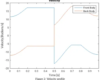
This relationship can also be seen in the MATLAB model shown in Figure 2.
Figure 2: Velocity profile
When the position of the front and rear legs are at a similar angle the two halves of the body rotate at different velocities. When the motor is turning clockwise or anticlockwise the front half of the robot will turn relatively slower than the rear section. At all other times when the velocity of one of the sections increases, because of the moment of inertia induced by the position of the legs, the velocity of the other section degreases.
As assumption in these calculation is that the power supplied to the turning motor can achieve the maximum velocity almost instantly. It can therefore be seen in Figure 2, the velocity of the rear section decreases as the line of the graph moves up and right, but the velocity of the front section increases as the line moves up and right. This is because the back is travelling in the opposite direction, and subsequently has a negative velocity.
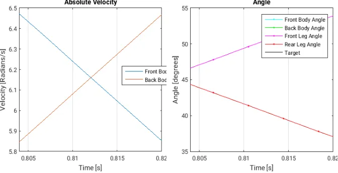
Figure 3: Absolute Velocity
As the two sections differ in weight, their minimum moment of inertia will be different. That is why the two sections rotate at different speeds depending on the position of the legs.
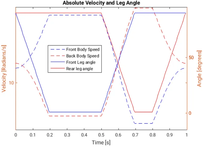
[image:29.595.127.466.418.663.2]The legs effect the velocity of the front and rear rotating sections. This can be seen clearly in Figure 4. It can be seen that the velocity is inversely proportional to the position of the legs.
With the current calculations using this model, the cat will invert after falling almost five meters over about 1 second. If a model is built to these specifications adjustments can be made by adding weight to the feet of the legs. These feet have been designed as hollow blocks to accommodate additional weight if necessary.
The two sections are rotating at a similar velocity when the front legs are at 72o and
the rear legs at 90o. The first time this occurs is at about 0.04 seconds after the fall starts,
[image:30.595.132.468.305.477.2]and then again at about 0.6 seconds. It can be seen in Figure 5, the angles are changing in the image on the right. This is because the velocity match occurs when the front legs are retracting and the rear legs extending.
The estimated position of the robot can be modelled by combining the previous graphs as can be seen in Figure 6.
Figure 6: Angle of Body and Legs
This figure displays the predicted angle of the robot's front and rear halves as a function of the velocity profile. Superimposed on the figure is the position of the legs as they rotate in and out. The time taken for the legs to extend and retract is the fastest theoretical time the motors can rotate.
The output of the Matlab file used to create this model is:
Final Front Body Angle: 179.8346 Final Rear Body Angle : 179.4509 Rotation Time: 0.99904s
Fall Height: 4.8956 m
7.1.5 Position detection method
This project is on mathematically modelling a falling robot. This robot has been dubbed a falling cat to indicate the methods intended to be studied for self correction. This title, falling cat, also indicates another property that the robot will have. More importantly, a property that the robot will not have. It is not proposed that the robot will have any ability to correct the direction of the fall.
When stationary on the surface of the Earth, or travelling parallel to the surface (perpendicular to the magnetic flux generated by gravity) an accelerometer, an animal's middle ear or other gravity detection system will detect an acceleration of 9.81 m/s2. In
free-fall the detection method would record zero.
This is proven by Equation 8 which indicates that the magnitude of acceleration when static is equal to 1g:
Equation 8: Total Acceleration when Static
A
=
√
A
x2+
A
2y+
A
2z=
1
g
(Tuck, 2007)Detecting zero would be a concern if the system was to activate only once the fall commenced. It is therefore proposed that any guidance system would be operational at all times, to detect a fall.
In space however an accelerometer would detect zero when the system is stabilised. Then whether from an external force, or gravitational pull from a planet, the accelerometer would detect the change in acceleration and react accordingly ("NASA -Acceleration Measurements Aboard The International Space Station", 2009).
In all instances of using an accelerometer, the dimensions that are known would be the orientation of the accelerometer to the body of the cat, and where in the cat the accelerometer is located. Using vectors the direction could be calculated. The direction of travel would continue to change until the front and rear halves are in the correct orientation and the acceleration is orientated correctly with the accelerometer.
Having sensors on the outside of the robot to detect changes in airflow, light or distance would not be as effective. Multiple sensors would be required as the initial conditions are not known. Errors may be induced if there is significant light falling onto concrete or other light coloured surface on a very bright day. This may produce errors with identifying the sky from the ground. Wind sensors may be confused with heavy cross winds and not effective in the vacuum of space. A distance sensor is only possible when a large enough object is within range of the sensors. Falling from the side of a building may confuse the sensor. It may interpret the wall of the building as the ground.
7.2 Review of Information
The literature which has reviewed prior to this report indicates that there has been previous research into the mechanical aspects of the falling cat. Research has also been identified dating back to a pre-computing era. It has also been noted that there is a period of scientific research which has been named after many scientists studied the falling cat phenomenon.
References listed in the papers mentioned in the previous sections contain additional literature which is yet to be reviewed closely, however it appears that there is significant detail for this topic. It however is yet to be identified in literature which has been reviewed prior to this report, that a study has been conducted into positional awareness of the robot, prior to release. Each example indicates that the robot needed to turn 180o prior to landing.
7.3 Project Feasibility Analysis
An investigation into the analysis of the mechanical falling cat is an intriguing topic which has been studied for over one hundred years. Attempts have been made to simulate the action of the falling cat, and some have been reported as successful. A comparison of the different methods of 'self-correction' have not been made, specifically with the device having a level of 'self-awareness'. That is the device will detect or calculate its position relative to a defined end position.
Broadly, the analysis of the mechanical falling cat will indicate: • the most appropriate method of self correction, and • the best method for application to a robotic falling cat.
8 PROJECT DEVELOPMENT
8.1 Aims, Objectives and Scope
The following aims and objectives are intended for the 2016 research topic:
• to create a suitable computer simulation of the mathematical model of the falling cat
• Identify the best method of self correction (leg swing; Tin can; flywheels; etc)
• Adapt the mathematical model for mechanization • to identify a suitable spacial position detection method if time permits
• Construct and test a robotic falling cat. • Compare robot results to computer simulation
8.2 Expected Outcomes and Benefits
Although the mechanics of a falling cat have been studied in some detail for some time, there seems to be little in the way of computer simulation or analysis of the best method for self correction.
The expected outcomes of the project include:
• Computer simulation of the mathematical modelling
• Suitable scale or grading system for assessment of the self correction techniques.
• A comparison of the identified methods of self correction if time permits
• a robotic falling cat
• Comparison of robot and simulation
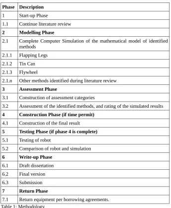
8.3 Methodology
Phase Description
1 Start-up Phase
1.1 Continue literature review
2 Modelling Phase
2.1 Complete Computer Simulation of the mathematical model of identified methods
2.1.1 Flapping Legs 2.1.2 Tin Can 2.1.3 Flywheel
2.1.n Other methods identified during literature review
3 Assessment Phase
3.1 Construction of assessment categories
3.2 Assessment of the identified methods, and rating of the simulated results
4 Construction Phase (if time permit)
4.1 Construction of the final result
5 Testing Phase (if phase 4 is complete)
5.1 Testing of robot
5.2 Comparison of robot and simulation
6 Write-up Phase
6.1 Draft dissertation 6.2 Final version 6.3 Submission
7 Return Phase
[image:35.595.126.471.100.519.2]8.4 Resource Requirements
Phase Item Quantity Source Cost
1.1 Internet Access Student Current Access 1.1 eResources As needed USQ –
Library Current Subscription 2 Matlab 1 (One) Student Current Software
(Student Edition) 3 Spreadsheet 1 (One) Student Current Software 4.1 Arduino Prototyping
Platform / motor controllers
1 (One) Student Current Inventory Arduino – 1 (one) Controller – 4 (four) 4.1 Wires/ solder/ tools/
prototyping equipment As needed Student $0.00 - $50.00 4.1 3D printer + consumables Per final
design USQ unknown 4.1 Electronic motors/ actuating
equipment As needed USQStudent Limit $100If available 5 Spreadsheet 1 (One) Student Current Software 6 Word Processing Software 1 (One) Student Current Software 7 Postage / Transport As needed Student Options:
Fuel $35.00 or
[image:36.595.126.471.80.410.2]9 PROJECT PLANNING
9.1 Risk Assessment
Risk Assessment Matrix
Severity Catastrophic
(1) Critical(2) Marginal(3) Negligible(4)
P
ro
ba
bi
lit
y
Frequent (A) HIGH HIGH CONCERNING MEDIUM
Probable (B) HIGH HIGH CONCERNING MEDIUM
Occasional
(C) HIGH CONCERNING MEDIUM LOW
Infrequent
(D) CONCERNING MEDIUM MEDIUM LOW Improbable
(E) MEDIUM MEDIUM LOW LOW
Eliminated
[image:37.595.123.472.127.427.2](F) ELIMINATED
9.1.1 Personal Risk Assessment
Task Hazard
Pre-Risk Controls Post-Risk
1.1 Office WPH&S 2.1 Office WPH&S 3.1 – 3.2 Office WPH&S
4.1 Burns to hands/ fingers B3 Correct use of soldering equipment E3 Burns to feet B2 Covered Shoes F
4.1 Cuts A3 Correct tool for stripping wire E3 4.1 Explosion – battery A1 Use of correct chargers. Not
over charge. Not short circuit E1 4.1 Pinch by motor/gear C4 Disconnect battery when
making modifications D4 5.1 Head injury B1 Keep test area clear E1
Bodily injury B2 Keep test area clear E1
5.1 Small pieces around
children B3 Vacuum after failed test D4 5.1 Fall from height A1 Test no greater then 2m E1 5.1 Injury from falling object A2 Keep animals clear of test
area E1 6.1 – 6.3 Office WPH&S
7.1 Standard Road related
[image:38.595.122.474.88.506.2]Project Risk Assessment
Task Hazard
Pre-Risk Controls Post-Risk
1.1; 2.1; 3.1 – 3.2; 6.1 – 6.3
Computer Failure –
Assignment loss D1 Backups – External tocomputer E4
2.1 – 2.n Fail to create working model B3
Ask for help – Contact Supervisor E4 4.1 Fail to create working
model B3 Ask for help – ContactSupervisor E4 4.1 USQ 3D Printer
unavailable D2 Plan to have printing donewith time to hand make parts if necessary.
D4
4.1 Insufficient funds to purchase supplies B2
Have funds available prior to need. D2 5.1 Robot has uncontrolled
deceleration exposure A1
Test on soft surface F
5.1 Another person breaks the robot A1
Not let anyone touch it E4
All Major communication issue with supervisor E1
Section see section 9.2 Communication Plan (page
[image:39.595.126.472.84.395.2]44) E3
9.2 Communication Plan
The communication plan for this project is relatively concise in nature. The project does not at this time involve any external organisation, and is primarily a computer based project. The communication with USQ will be via the supervisor. In this instance the supervisor and the course coordinator are the same individual.
Prior to writing this report there has been communication between the student and the supervisor. The communication has related to this subject as well as other subjects the student has taken whilst studying. To date, the communication has been professional and supportive and there is no foreseen communication issues.
As the supervisor is the final contact for this course an alternative has been developed in the event that communication has broken down, see Table 6: Communication Plan.
Nature of
Communication ExpectedFrequency Proposed Contact
Administrative
Matter Low Carolyn Saffron (Administration) Report
Related Matter Very High Chris Snook (Supervisor) – or as guided Subject
Related Matter
Extreme Chris Snook (Supervisor) – or as guided
Major Project
Matter Moderate Chris Snook (Examiner) – or as guided Matter Relating
to Supervisor
Low Ray Malpress (Mechanical Assistant Examiner) – or as guided
Major Unresolved Matter
[image:40.595.128.469.330.545.2]Unlikely USQ Formal Appeals Process
Table 6: Communication Plan
9.3 Special Requirements
In the event that sufficient time permits, the use of the USQ 3D printer would assist in making a professional robot. This use is highly likely to be via a technician after initial plans have been approved by the supervisor.
9.4 Project Schedule
[image:41.595.128.469.238.382.2]The current plan for the schedule of events is displayed in Table 7: Gantt Project Schedule. It is noted that the possible events which will impact on the development of the project have been listed in red, and the green bar is the scheduled mid year break. The expected events which will impact on the available time are the exam blocks for the other subjects which will be studied concurrently with the project, and when my three children are home from school on primary school holidays. When the assessment requirements of other subjects becomes available, this chart will be updated.
10 CONSTRUCTION
It is acknowledged that the construction of a robot is not a normal topic for reporting in a thesis such as this one. However, there were obstacles experienced during this project which if known prior to commencement, may have changed the course of the project. Briefly discussing these topics will possibly assist the next researcher in not taking the same time to begin testing.
10.1 Motors
Driving the legs of the robot, and spinning the middle section is a critical component in making a robot which uses the inertial turn technique. From calculations in Equation 4 time of fall [page 28], the time available for the robot to free fall is very limited. The robot will quickly reach the velocity of a car travelling on a road (Figure 7: Distance and Velocity), and therefore tests need to be kept to very short heights.
0 0.5 1 1.5 2 2.5 3
0 5 10 15 20 25 30 35 0 10 20 30 40 50
Distance and Velocity
Distance [m] Velocity [km/h]
[image:42.595.130.465.353.572.2]Time [s] Ve lo ci ty [m /s ] D is ta n ce [m ]
Figure 7: Distance and Velocity
The precision of angle can be controlled with timing controls in the the micro controller. The need for power and speed continues to be important, but precision to the a specified angle is not as important as first believed.
The position of the legs can be controlled using stop blocks. Have fast powerful motors swing the legs to fully retracted, or fully extended positions and have the movement of the legs halt with immoveable blocks. The use of powerful stepper motors added a complexity, and weight which was not needed. This weight also changed the control in changing the moment of inertia as the mass of the motors was significantly more than the mass of the printed legs. The relatively massive NEMA 23 stepper motor shown in Image 4 is 1.6 kg (Appendix D – Stepper motor datasheets, 14.4.2 Stepper Motor NEMA 23).
Image 4: NEMA 17 & 23 stepper motors
The size difference between the two motors can be seen in Image 5. The NEMA 23 was required for the delivery of torque, and as a 24 V motor it could rotate quickly, but this created additional difficulties with the legs.
One of the most prominent difficulties created by the heavy body was the mass of the feet. The point load calculations in 7.1.4.1.4 Inertia Calculations [page 28] were intended to be used to fine tune the rate of rotation. That is, they were to make allowances for small differences in mass from the front to the back of the robot. As discussed in previous sections the distance L plus half the height of the foot is 15 cm (Drawing 1 [page 29] Reproduced below).
Reproduced - Drawing 1: Dimension Nomenclature
The datasheet for the NEMA 17 (Appendix D – Stepper motor datasheets 14.4.1 Stepper Motor NEMA 17) lists a holding torque of 6.5 kg.cm. Therefore, the maximum mass the holding torque can have at the feet is 0.4 kg, or 0.2 kg per foot, minus the mass of the printed components. The combined mass of the feet and legs is about 100g.
10.2 Motor control modules
An attempt to drive the motors was made with the four amp stepper driver module show in Image 6. This is listed as a four amp controller module. The NEMA 23 stepper motor is listed as a four amp stepper motor. It has since been discovered (as a mechanical major I was unaware of) four amp stepper motors can draw a maximum of eight amps. The listed driver module supplies two amps per channel. The writer subsequently burned out a number of control modules before becoming aware of this phenomenon.
Image 6: Stepper controller module
Image 7: Relay motor controller
The schematic for this relay driver is displayed in Drawing 2. With this motor controller results were obtainable see (11 RESULTS (OBJECTIVES) [page 53])
Drawing 2: Relay motor controller schematic
M
VccM
Diode
Switch ( Relay )
10.3 Printed Parts
The printing of the components was done at University of Southern Queensland, Toowoomba (see Acknowledgements [page 7]). The parts were printed with a hollow core similar to a square honeycomb. The use of sharp edges and defined corners on the robot introduce a number of stress concentration points. Which were taken out in late version of the parts. The newer design had radii on the edges (left Image 8) whereas the old design had sharp corners (right Image 8).
Image 8: Change in component design
Whilst tapping the lugs seen in Image 8 it was fairly common to knock the lug off, or if the part was dropped they would break off. As there were additional parts used, these damaged parts were used to create a glue for other components which broke (Image 9)
Image 9: Parts in Acetone
During design the gears and pinions for rotating the legs were drawn according to the ribbed belt available to the writer. However, when the parts were printed, swelling and shrinking of the teeth no longer permitted the belt to sit snugly. It was therefore decided to use aluminium toothed gears Image 10.
Image 10: Leg Axle Pinion
10.4 Testing
During construction it was identified that the driving of the motors was the biggest hurdle to overcome. The motor selection influenced how heavy the robot was, as well as how fast it would turn over. Initially it was believed that testing had failed due to the height the robot needed to fall from, and the damage this would cause without a suitable system to catch the robot. A suggestion from David Buttsworth during the residential school component of this subject was to test the robot vertically. That is hold the robot from one end and time the duration it takes to make a complete revolution. This is the method that was used to produce some test results as can be seen in 11 RESULTS (OBJECTIVES) [page 53].
11 RESULTS (OBJECTIVES)
Section 8.1 Aims, Objectives and Scope [page 38] lists the desired outcomes of this report. For completeness the outcomes are listed as headings in this section.
11.1 Identify the best method – met
The best method of self correction of a falling cat is obviously up to the cat. However mathematically there are a number of qualifying remarks which need to be made on this statement. Firstly, the method used to model the falling cat was the inertial turn technique. That is the cat swings its legs about and twists over during the fall. This method is the easiest of the methods to model and construct.
Although this model is the easiest it doesn't imply that it was without challenges as detailed in this report. Any change to components or positions will impact on how the robot changes position. This method is easier to process when small processing boards like the Arduino are used. It can also be mechanised with traditional motors, or stepper motors.
The other method is the tin can turn. This method involves the cat bending forward sideways and backwards during the fall, which produces an angular velocity causing rotation. This method is much harder to model, and papers written on the subject require knowledge of Gauge Theory. This is out of the scope of the writers knowledge. The only known robot made by a university in Japan used a series of actuators to simulate the tendons in the animal.
This tin can turn requires processing faster than that offered by the Arduino, as well as sufficient on-board storage space to hold the code. It is believed that the Japanese attempt was connected to a computer for testing.
To answer the objective of the report directly, the best method identified for mechanisation is the inertial turn method discussed in this report.
11.2 Create a computer simulation – met
To answer the objective of the report directly, the a computer simulation was created and run using MATLAB software.
11.3 Adapt the model for mechanization – met
To have the model as adaptable as possible there are a number of variables that need to be adjusted to suit the components intended to be used in the robot. The full code can be seen in appendix B – MATLAB Code 14.2.4 Code. Reproduced here are a few examples of where the code can be adapted to the model.
% Mass of a motor [kg] motor1_mass = 0.42; % Width of motor [cm] motor1_width = 4.2; % Depth motor [cm] motor1_depth = 4.2; % Supply voltage to body motor [V] motor1_voltage = 3.36; % Inductance of drive motor [mH] motor1_inductance = 3*10^3; % Steps per revolution of motor. motor1_steps = 200; % Distance from drive to start of a leg [cm] leg_r = 5.5; % Length of a leg [cm]/100 == [m] leg_L = 15;
The code above indicates a number of constants which can be changed for adaptation to a model. Once the model was printed the values listed were adjusted to the real world values. For example, the initial prediction of the mass of a leg was 50 g, however the printed component's mass was 17 g. This was adjusted to compare the simulation to the model.
11.4 Identify a spacial position detection method –
met
The use of the accelerometer is the best system identified for direction of fall. The methods discussed in 7.1.5 Position detection method [page 35] indicate that the other passive sensors that could be used would not be as effective. Passive sensors are those similar to wind speed, distance and light sensors.
To answer the objective of the report directly the spacial position detection method identified was the use of accelerometers. Although not used in the tests conducted and reported below, due to vertical testing the accelerometer would work in gravity as well as locations without gravity.
11.5 Construct and test a robotic falling cat – met
Image 11: Test Setup [below] is a photograph of the method used to hold the robot for testing. It was not possible to allow the robot to free fall as the sudden deceleration at the end would destroy the robot and components. That is unless a suitable system of catching the robot was used. Due to the weight of the robot, approximately 5 kg, this was out of the scope of the report.
Image 11: Test Setup
11.6 Compare robot results to computer simulation
– met
This project was attempted by Drury University of Missouri and on of the students James Stockton who was on this project is reported as saying (Shoemake, 2014):
“The most frustrating part of the experiment has been the actual fabrication of the robot. It's a relatively simple matter to show that it should work, but an amazingly
difficult exercise in precision to actually get it to do what we want”
This was the hardest part of this project, particularly as it was not conducted in a group setting.
Results for the NEMA 17 motor as the drive motor are is Figure 8. The tine it took to make a 180o turn was significantly more than the theoretical times. This could be due
to the motor controller that I used, or the Arduino isn't sending an optimal pulse to the controller. Initially the Arduino was set to send the pulse according to the theoretical time between pulses, however I found the lack of available torque was significant. The other possibility is that the NEMA 17's do not have the holding torque to spin the increased mass of the extending legs. It is beyond the scope of this report to investigate the optimum drive speed, and what was occurring with the circuitry.
1 2 3 4 5
0 2 4 6 8 10 12
Robot Vertical Sping Test
NEMA 17
Model NEMA 17 Robot NEMA 17
[image:53.595.128.464.395.640.2]Test Number Ti m e [s ]
Due to the results that I obtained for the NEMA 17 motor, the relay motor controller was connected to the Arduino and the NEMA 23 was re-installed. The relay motor controller didn't run correctly when the standard Arduino stepper motor libraries were used, the eight pins of the relay driver were connected to eight pins of the Arduino and each driven with digital HIGH and LOW signals.
It is noted that the NEMA 23 achieved a better result than the NEMA 17, with about one and a half times the theoretical time (Figure 9). This could be because at the higher speeds switch bounce was occurring, or perhaps an element of back EMF was hindering the change in current. This electrical issues are also beyond the scope of this report.
1 2 3 4 5
0 0.5 1 1.5 2 2.5
Robot Vertical Spin Test
NEMA 23 (with relay control module)
Model NEMA 23 Robot NEMA 23
[image:54.595.127.468.260.555.2]Test Number Ti m e [s ]
Figure 9: NEMA 23 Test Results
Having the robot timing match the theoretical values exactly was not explored in this report. There are a number of possibilities and due to time parameters it is not possible to investigate them all. A working model was produced, and refined to the standard shown. The values for the results are listed in Figure 8 and Figure 9 are displayed in Table 8 and Table 9 respectively.
Test Number 1 2 3 4 5
Model NEMA 17 1.8979 1.8979 1.8979 1.8979 1.8979
Robot NEMA 17 9.40 9.15 9.72 9.30 8.82
Test Number 1 2 3 4 5
Model NEMA 23 1.003 1.003 1.003 1.003 1.003
[image:55.595.125.470.53.102.2]Robot NEMA 23 1.46 1.37 1.92 1.11 1.34
Table 9: NEMA 23 Test Result Data
12 CONCLUSION
The overall report was successful in identifying methods for the self-correction of a robot. It can be seen that there are advantages and disadvantages in the Tin-Can-Turn as well as the Inertial Turn. Linking the methods of self correction back to how the cat identifies which methods are beyond the scope of this report.
Literature on the methods of self correction of a cat date back to the 1800's, where scientists and physicists were fascinated by how the cat could twist its body. It wasn't until the invention of the high speed camera that humans could see the reactions of the cat. By slowing down the fall, with the use of the high speed camera, humans could begin to understand what was happening.
The two major theories for how the cat turns over, Tin-Can-Turn and Inertial Turn, have almost equal number of supporters. Both methods can be modelled mathematically, and there have been robots produced which mimic both.
Mathematical models of the Inertial Turn methods were produced in this report and comparing this to the test results clearly identifies the need to have accurate measurements of the components that are used in the model. The masses of the external components used to change the moment of inertia of the front and rear section are critical in predicting the robots theoretical performance.
A number of problems arose during the construction phase which would have been less time consuming if students of multiple disciplines were working on this project. These problems were eventually resolved, in some instances by crude methods. One of the crude methods is the mechanical relay motor controller, this would not be a long term solution.
Each of the objectives of the project have been completed and reported in section 11. Graphs and tables of results have also been produced of the results obtained. There is scope for improvement of the robot as the values recorded are longer than the theoretical values.
13 BIBLIOGRAPHY
Advanced
Diving
Systems
2015,
Risk
Assessment,,
http://www.advanceddivingsystems.com/RiskAssessment.aspx
Crane, Ralph 1968, A Copycat Astronaut, 7, Life Inc
Deveshvar, Manisha 2015 , Why do Cats Always Land on Their Feet?,,
http://www.pitara.com/science-for-kids/5ws-and-h/why-do-cats-always-land-on-their-feet/
Ellie Zolfagharifard 2013,Ever wondered how cats and pigeons react in zero
gravity?,Mail Online
Fiorentino, Matt 2012,Ten Stats That Will Change the Way You Look At Video in
2013,Web Article
Franklin, W. S. 1911, HOW TO THROW A CURVED BALL, Science, Vol:34,
page(s):844-845,
Kane, T.R. and Scher, M.P. 1969, A Dynamical Explanation of the Falling Cat
Phenomenon, International Journal of Solids and Structures, Vol:5,
page(s):663-669,
Kawamura, Takashi 2014, Understanding of Falling Cat Phenomenon and
Realization by Robot, Journal of Robotics and Mechatronics, Vol:26, page(s):,
Madrigal, Alexis C 2011, Video: Deducing the Physics of How Cats Fall, , Vol:,
page(s):,
http://www.theatlantic.com/technology/archive/2011/09/video-deducing-the-physics-of-how-cats-fall/244842/
Mannoni, Laurent , Who's Who of Victorian Cinema :: Etienne-Jules Marrey
(1830-1904),, http://www.victorian-cinema.net/marey
McDonald, Dr Donald , How Does a Cat Fall on its Feet?, , Vol:7,
page(s):1647-1649,
Montgomery, Richard 1993, Gauge Theory of the Falling Cat, Fields Institute
Communications
Shields, Ben; Robertson, William S. P.; Redmond, Natalie; Jobson, Ross; Visser,
Rian; Prime, Zebb; Cazzolato,Ben 2013, Falling Cat Robot Lands on its Feet,
Sunquist, Fiona; Sunquist, Mel 2014, The Wild Cat Book: Everything You Ever
Wanted to Know about Cats, , University of Chicago Press
"Ponoko - United States - Ponoko | Ponoko". Ponoko.com. N.p., 2016. Web.
"Stepper Motor Calculator". Daycounter.com. N.p., 2016. Web
Shoemake, Stacy. "Building One-Of-A-Kind Robot To Test In Zero-Gravity".
Spacedaily.com. N.p., 2004. Web. 1 Jun. 2016.
Tuck, Kimberly. "Measuring Freefall Using Freescale’S MMA7360L 3-Axis
Accelerometer". NXP Semiconductors. N.p., 2007. Web. 13 Jun. 2016.
14 Appendix
14.2 B – MATLAB Code
14.2.1 Glossary of Variables
Variable Description
accumulated_steps A count of the number of steps the robot has taken to turn over.
angle_step The angle of each step
angle_step_front The step angle of the front half of the body. Normally not used, however with different stepper motors this may become important.
angle_step_rear The step angle of the rear half of the body. Normally not used, however with different stepper motors this may become important.
body_angle A matrix containing the angle of the front half, and rear half, and final angle with respect to the ground.
[front, rear, goal]
body_speed A matrix containing the velocity of the front half, rear half, and time.
[time, front, rear]
face_length The average length of each face that makes the robot.
face_mass The average mass of each face.
foot_front_mass Mass of one of the front feet. It is possible to weight the feet with steel or lead.
foot_height The height of a foot.
foot_L The distance from the axis of a leg to the centre of gravity of a foot.
foot_rear_mass Mass of one of the rear feet. See
foot_front_mass
hAx1 Handle of the two axes created in the plotting routines. Used to set axis limits, has no impact on robot.
hAx2 See hAx1
hLine1 Handle of the graphics objects created in the plotting routines. Used to set colour, has no impact on robot.
hLine2 See hLine1
hLine3 See hLine1
hLine4 See hLine1
IBack An input variable in SpeedofBody function that holds the moment of inertia of the back section.
IBody An input variable in MoI_Body function that holds the moment of inertia of the body of the robot.
IFoot An input variable in MoI_Body function that holds the moment of inertia of a foot.
IFront An input variable in SpeedofBody function that holds the moment of inertia of the Front section.
Ileg An input variable in SpeedofBody function that holds the moment of inertia of the leg.
Imax An input variable in Motor_RPM_max function that holds the maximum current of the motor.
L An input variable used in MoI_Leg and
MoI_Foot functions that holds the length of the leg.
An input variable used in Motor_RPM_max
function that holds the inductance of the motor.
leg_angle A matrix that records the current leg angle of the front and rear legs, and time.
[time, front, rear]
leg_angle_max Maximum permitted leg angle. Used to restrict movement of the legs.
leg_angle_min Minimum permitted leg angle. Used to restrict movement of the legs
leg_front_angle Instantaneous angle of the front legs used during processing.
leg_L Length of the leg
leg_mass Mass of the leg
leg_r Distance from axle to start of leg.
leg_rear_angle Instantaneous angle of the rear legs used during processing.
M An input variable used in MoI_H_Box and
MoI_Leg functions that holds the mass of the parts.
MoI_front Instantaneous moment of inertia of the front section.
MoI_front_body Instantaneous moment of inertia of the front body and all the components.
MoI_leg_swing A matrix that records the current moment of inertia of the legs and the angle at which they have been set. Not used in calculation of rotation, used in test phase for moment of inertia vs leg position.
MoI_motor_drive Moment of inertia of the drive motor
MoI_motor_legs Moment of inertia of the leg motors
MoI_rear Instantaneous moment of inertia of the rear section.
MoI_rear_body Instantaneous moment of inertia of the rear body and all the components.
MoI_skin Moment of inertia of the shell only
MoI_v_leg_step_size A calculated constant for spacing of the moment of inertia vs leg position graph
MoIB Return value of MoI_Body and MoI_H_Box
functions.
MoIF Return value of MoI_Foot function
MoIL Return value of MoI_Leg function
MoIM Return value of MoI_Motor function
motor1_current Datasheet listing of the maximum current for drive motor
motor1_depth Depth of drive motor
motor1_inductance Datasheet listing of inductance for drive motor
motor1_mass Mass of drive motor
motor1_speed_max Theoretical maximum speed (calculated) of the drive motor.
motor1_steps Steps per revolution of the drive motor
motor1_voltage Maximum voltage of the drive motor
motor1_width Width of the drive motor
motor2_current Datasheet listing of the maximum current of the leg motors
motor2_depth Depth of the drive motor
motor2_inductance Datasheet listing of inductance for the leg motors
motor2_mass Mass of the leg motors
motor2_steps Steps per revolution of the leg motors
motor2_voltage Maximum voltage of the leg motors
motor2_width Width of the leg motors
r An input variable used in MoI_Leg function that holds the distance from the central axis to the start of the leg
An input variable used in MoI_Foot function that holds the length of the leg
R A variable used in MoI_Leg function that holds the total distance from the central axis to the foot.
rotation_leg_move_stepsConstant; number of steps to move the legs from retracted to extended.
rotation_second_steps Constant; number of steps to turn to finalise the self-correction.
rps Return value of Motor_RPM_max
An input variable used in SpeedofBody
function that holds the revolutions per second of the motor.
step_count Number of steps to take when performing calculations. Equivalent to Δx
Step_Counter A time keeping variable; used to count the number of steps that have occurred in the function.
steps An input variable used in Motor_RPM_max
function that holds the steps per revolution of the motor.
theta An input variable used in MoI_Leg function that holds the current angle of the leg
time_current A time keeping variable; records time since beginning of calculations


![Table 3: Risk Assessment Matrix (Adapted from [ADS, 2015])](https://thumb-us.123doks.com/thumbv2/123dok_us/147619.24763/37.595.123.472.127.427/table-risk-assessment-matrix-adapted-ads.webp)


