University of Southern Queensland
Faculty of Engineering and Surveying
Evaluation of the use of
Safety Barriers on
Roundabouts
A Dissertation submitted by
Jake James
In fulfilment of the requirements of
ENG4111 and 41112 Research Project
Towards the degree of
Bachelor of Engineering (Civil)
1
Abstract
Roundabouts are standard intersection treatments that can be found throughout the world. They have proven safety benefits over conventional intersections when it comes to crash severity. In certain circumstances it can also be noted that traffic flows can be more efficient with a roundabout arrangement.
Over time the design standards of roundabouts have changed and improved. As these developments occur a number of existing roundabouts can remain that were design based on outdated knowledge. This development can leave a legacy of existing roundabouts with known deficiencies causing an unsafe environment for road users. This report has identified that this is a prevalent issue on NSW roads due to a lack of development in standards relating to roundabouts that now can be seen to have promoted geometric deficiencies in high speed roundabouts.
As with the design standards, methods to treat design deficiencies and desirable safety outcome have also changed. It is common practice to conduct a cost benefit analysis to determine which treatment is most suitable for the intersection. In previous design development, safety barriers have been excessively used as the treatments are heavily based on benefit cost ratios which they perform well in. These analysis’s suit barriers as they are a cheap solution that reduces the severity of the crash and therefore reduces injury and cost to state. Movement has begun to introduce a safe systems approach to treatments where by treatments to remove the cause of the incidents be a primary focus. This no longer suites safety barriers, as they do not alter the occurrence of crashes only reduce the impact of crashes.
Safety barriers are designed to operate in certain circumstances with ideal conditions of impact. Due to the circular nature of roundabouts it is difficult to predict the speed and angle of impact that will be made between a collision with a barrier and a vehicle. This report has found that safety barriers cannot be expected to operate in an ideal manor at roundabout locations.
2
Limitations of use
The Council of the University of Southern Queensland, its Faculty of Engineering and Surveying and the staff of the University of Southern Queensland, do not accept any responsibility for the truth, accuracy or completeness of material contained within or associated with this dissertation.
Persons using all or any part of this material do so at their own risk, and not at the risk of the Council of the University of Southern Queensland, its Faculty of Engineering and Surveying or the staff of the University of Southern Queensland.
Certification
I certify that the ideas, designs and experimental work, results, analyses and conclusions set out in this
dissertation are entirely my own effort, except where otherwise indicated and acknowledged.
I further certify that the work is original and has not been previously submitted for assessment in any
other course or institution, except where specifically stated.
Jake James
Student Number: 001019063
4
Acknowledgments
I would like to thank a number of people for their support and assistance throughout the course of this dissertation. I would like to thank my RMS colleagues in particular Justin Miles, Jeffrey Callaghan and Nigel Maugham for their continued guidance, expertise and support throughout the completion of this project. I would also like to acknowledge the support of my project supervisor Trevor Drysdale for his ongoing feedback and guidance.
Lastly I would like to thank my friends and family for their ongoing support and understanding throughout the completion of this dissertation and through the completion of all my academic studies.
5
Contents
Abstract ... 1
Limitations of use ... 2
Certification ... 3
Acknowledgments ... 4
Contents ... 5
List of Figures ... 7
List of Tables ... 8
1 Introduction ... 10
1.1 Background ... 10
1.2 Project Objectives ... 11
1.3 Personal Objectives ... 12
2 Literature review ... 13
2.1 Design for Road Safety ... 13
2.2 Roundabout Crash Patterns ... 14
2.2.1 Crash Types ... 16
2.3 Design Methods and Standards for Roundabouts ... 20
2.3.1 Austroads Design for Roundabouts ... 20
2.3.2 NSW Supplement to Austroads ... 25
2.3.3 Comparison of methods and standards: ... 29
2.4 Safety Barriers ... 30
2.4.1 Typical Barrier Installations ... 30
2.4.2 Severity Index of Barriers ... 32
3 Methodology ... 35
3.1 Literature review ... 35
3.2 Site Assessments ... 35
6
3.2.2 Site Visit ... 36
3.2.3 Geometric Review ... 36
3.2.4 Crash Data Analysis ... 37
3.2.5 Data review ... 37
3.2.6 Data limitations ... 37
3.3 Site Overviews ... 37
3.3.1 Site 1 – Crystal Street, Forresters Beach ... 37
3.3.2 Site 2 – Brittania Drive, Wyong ... 38
3.3.3 Site 3 – Johns Road, Wadalba ... 39
3.3.4 Site 4 – Pindarri Avenue, Berkley Vale ... 40
3.3.5 Site 5 – Chelmsford Road, Charmhaven ... 41
3.3.6 Site 6 – Geoffrey Road, Chittaway Bay ... 43
3.3.7 Site 7 – Mingara Drive, Tumbi Umbi ... 44
3.3.8 Site 8 – Cresthaven Avenue, Bateau Bay ... 45
4 Results and Analysis ... 46
4.1 Site 1 – Crystal Street, Forresters Beach ... 47
4.2 Site 2 – Brittania Drive, Wyong ... 50
4.3 Site 3 – Johns Road, Wadalba ... 53
4.4 Site 4 – Pindarri Avenue, Berkley Vale ... 56
4.5 Site 5 – Chelmsford Road, Charmhaven ... 59
4.6 Site 6 – Geoffrey Road, Chittaway Bay ... 62
4.7 Site 7 – Mingara Drive, Tumbi Umbi ... 65
4.8 Site 8 – Cresthaven Avenue, Bateau Bay ... 68
5 Results and discussion ... 71
5.1 Geometric analysis ... 71
5.1.1 Central Island Size ... 71
5.1.2 Approach/Departure geometry ... 73
7
5.3 Injury reduction ... 76
6 Conclusion and Recommendations ... 79
6.1 Conclusion ... 79
6.2 Safety Barriers used from a Safe Systems perspective ... 79
6.3 Recommendations ... 80
6.4 Limitations ... 81
6.5 Further Work ... 81
Reference List ... 82
Appendix ... 84
Appendix A – Project Specification ... 84
Appendix B – Risk Assessment ... 85
Appendix C – Crash History Data ... 86
List of Figures
Figure 1 – Intersection conflict points (US Department of transport, 2000) ... 14Figure 2 – Relative intersection speeds (Department Main Roads 2006) ... 15
Figure 3 – Typical Roundabout crash types (Department Main Roads 2006) ... 17
Figure 4 – Accident type breakdown (US Department of transport, 2000) ... 18
Figure 5 – Accident type diagram (US Department of transport, 2000) ... 19
Figure 6 – Minimum central island radius (Austroads 2015) ... 23
Figure 7 – Typical roundabout geometry (Austroads 2015) ... 23
Figure 8 – Alternative approach geometry (Austroads 2015) ... 24
Figure 9 – Maximum entry path radius (Austroads 2015) ... 24
Figure 10 – Entry path construction (Austroads 2015) ... 25
Figure 11 – Roundabout component overview (RTA Austroads Guide Supplement, 2009) ... 26
Figure 12 – Minimum inscribed circle radii (RTA Austroads Guide Supplement, 2009) ... 27
8
Figure 14 – Layout circle calculation (RTA Austroads Guide Supplement, 2009) ... 28
Figure 15 – Circulating carriageway width (RTA Austroads Guide Supplement, 2009) ... 29
Figure 16 – Barrier installations at intersection (RTA Road Design Guide) ... 31
Figure 17 – Severity index relative cost (Austroads 2016) ... 32
Figure 18 – Severity Indices of barriers (RTA Road Design Guide, 1996) ... 33
Figure 19 – Severity indices (Austroads Guide to Road Design, 2009) ... 34
Figure 20 – Pacific Highway, Crystal Street intersection ... 38
Figure 21 – Pacific Highway, Brittania Drive intersection ... 39
Figure 22 – Pacific Highway, Johns Road intersection ... 40
Figure 23 – Wyong Road, Pindarri Avenue intersection ... 41
Figure 24 – Chelmsford Road Pacific Highway intersection ... 42
Figure 25 – Wyong Road, Geoffrey Road intersection ... 43
Figure 26 – Wyong Road, Mingara Drive intersection ... 44
Figure 27 – Central Coast Highway, Cresthaven Avenue intersection ... 45
Figure 28 – Central Island Size Compliance ... 72
Figure 29 – Average Central Island Size ... 72
Figure 30 – Approach Geometry Compliance ... 73
Figure 31 – Off Carriageway Crash Occurrence ... 74
Figure 32 – Approach Compliance against Crash Occurrence ... 75
Figure 33 – Roundabout Crash Injuries against Manoeuvres ... 76
Figure 34 – Safety Barrier Treatment Coverage ... 77
Figure 35 – Injury Occurrence against Barrier Protection ... 77
List of Tables
Table 1 – Geometric Compliance Index ... 46Table 2 – Roundabout Manoeuvre Risk Assessment ... 46
Table 3 – Site 1 Geometric Analysis Summary ... 47
9
Table 5 – Site 2 Geometric Analysis Summary ... 50
Table 6 – Site 2 Roundabout Manoeuvre Crash Analysis ... 51
Table 7 – Site 3 Geometric Analysis Summary ... 53
Table 8 – Site 3 Roundabout Manoeuvre Crash Analysis ... 54
Table 9 – Site 4 Geometric Analysis Summary ... 56
Table 10 – Site 4 Roundabout Manoeuvre Crash Analysis ... 57
Table 11 – Site 5 Geometric Analysis Summary ... 59
Table 12 – Site 5 Roundabout Manoeuvre Crash Analysis ... 60
Table 13 – Site 6 Geometric Analysis Summary ... 62
Table 14 – Site 6 Roundabout Manoeuvre Crash Analysis ... 63
Table 15 – Site 7 Geometric Analysis Summary ... 65
Table 16 – Site 7 Roundabout Manoeuvre Crash Analysis ... 66
Table 17 – Site 8 Geometric Analysis Summary ... 68
10
1
Introduction
Roundabouts are a common intersection treatment throughout Australia and the world. In general, they are very safe and efficient intersections with low crash rates and good traffic efficiency. Roundabouts are generally provided as a cheaper alternative to the provision of traffic signals. The decision to upgrade or construct a new roundabout is made on a number of factors such as the traffic volumes, speed environment, safety benefits and cost.
A problem arises with roundabouts when the conditions that warranted their need change or a deficiency is identified. Increases in traffic volumes, changes in road surface or unforeseen design deficiencies can lead to a safety issue becoming apparent. To eliminate a safety issue on a roundabout will involve extensive construction and come at a large cost. It has become more and more common for the installation of safety barriers on roundabouts particularly on the departures. The barriers offer a much cheaper alternative to the issue and minimise the severity of crashes caused rather than to eliminate them.
In general, safety barriers are designed to be parallel to a road carriageway. The angle of impact a barrier is effective over is an important characteristic of each different barrier type. In general barriers are designed to be parallel to a road carriageway to minimise the impact of off carriageway crashes into hazards in the roadside corridor. This presents a problem for their implementation on roundabouts as due to the radial nature of the manoeuvres vehicles are required to take. This can create a large variety of possible impact angles potentially affecting the barriers performance.
This report aims to investigate the use of safety barriers on roundabouts within Australia to determine if they provide a benefit in treating roundabouts with a high occurrence of off carriageway crashes. This project is relevant too rural and semi-rural roundabouts with high design speeds.
1.1
Background
Through the authors experience as a road designer with involvement in remedial works on roundabouts due to repeated crash patterns, it became increasing common for barriers systems to be implemented as a method to reduce the severity of crashes. The reliance on barriers being used to provide a benefit in situations they were not ideally suited for was questionable as barriers themselves can be considered a hazard when impacted.
11 works involved in improving geometry and road surface cannot be seen as direct treatments to reduce the severity of crashes.
When looking at barriers approved for use within NSW it is noted that they are specified for relatively low crash angles that may not be appropriate for roundabouts where the angle of impact was largely varied. This is not considered in assumptions of barrier performance and may be leading towards inaccurate cost benefit analyses justifying treatments.
Justification for treatments reducing the injury impact rather than the reducing the likelihood of crashes has been encouraged within Australia. This is a safe systems approach and is in contradiction to the cost benefit analysis method used to justify safety barrier installations.
This study aims to look at real world sites in NSW to review the implementation of safety barriers on roundabouts as a treatment to the high occurrence of off carriageway crashes. This is to investigate the treatment in terms of its assumed performance as well as its justification as a treatment based on modern road design methodology and recent policy.
1.2
Project Objectives
Safety barrier systems are deployed to reduce the severity of crashes which cause cannot be eliminated. This will be the focus of the project as it will investigate the causes of their implementation and the effectiveness at reducing the severity. The performance of these barriers to reduce severity of crashes will need to be compared with alternative treatments.
The overall objectives of this project were to:
Determine the most common and severe crash types on roundabouts leading to the installation of safety barriers.
Evaluate current approved barriers for effectiveness when impacted by the most critically determined crash situations on roundabouts.
Evaluate the performance of sites where barriers have been implemented and alternative treatments for comparison of performance.
Determine a set of recommendations that outline the most appropriate treatment for safety improvements at roundabouts based on site specific conditions and crash patterns.
12
1.3
Personal Objectives
Through the completion of this report I hope to achieve the following personal objectives:
Understand the differing design methodology and best practice methods used within Australia.
13
2
Literature review
A literature review has been undertaken as part to provide information on subjects relevant to the project objectives.
Researching the different standards used to design roundabouts between governing bodies both within Australia and globally will provided an insight in potential deficiencies inherently created in different areas. This will also provide a general understanding of industry best practice.
Roundabout crash patterns will be researched to determine the most likely impacts to be expected on safety barriers within roundabout environments. Safety barriers will be researched to determine how they could be affecting crashes within this environment.
2.1
Design for Road Safety
In NSW a Safe System approach is used when assessing road safety. The rationale behind this is to reduce deaths and serious injuries. The approach aims for zero tolerance so that no death or serious injury on our road network is acceptable.
A Safe System approach to road safety is holistic approach that recognises that humans as road users will make mistakes. The system encompasses multiple elements including the road speed, the road users, road environment and vehicles. All of these elements are designed to work as a system where if one component fails the other systems can work to reduce the impact of the resulting incident. The Australian transport council (2011) indicates that the Safe System approach requires, in part:
Roads and roadsides designed and maintained to reduce the risk of crashes occurring and to lessen the severity of injury if a crash does occur. Safe roads prevent unintended use through design and encourage safe behaviour by users.
Provision of forgiving road environments that prevent serious injury or death when crashes occur.
Align speed limits with the risk and function of the road and roadside environment.
14
2.2
Roundabout Crash Patterns
It is well documented that roundabouts have many safety benefits when compare to standard un-signalised intersections. Roundabouts improve safety by eliminating conflict points, reducing speed differentials and encouraging slower speeds through the intersection. Crashes within roundabouts can be looked at in the following more detailed elements.
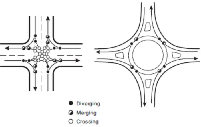
[image:15.595.129.481.317.540.2]Conflict Points: Conflict points are the locations on an intersection where a vehicle movement through the intersection crosses the path of another movement. Roundabouts reduce the total amount of conflict points when compared to standard intersections layouts and also remove the most severe types of conflict points where vehicles cross one another with potential for a large speed differential. The diagram below illustrates the reduction of conflict points on a standard four leg intersection layout in comparison with a roundabout.
Figure 1 – Intersection conflict points (US Department of transport, 2000)
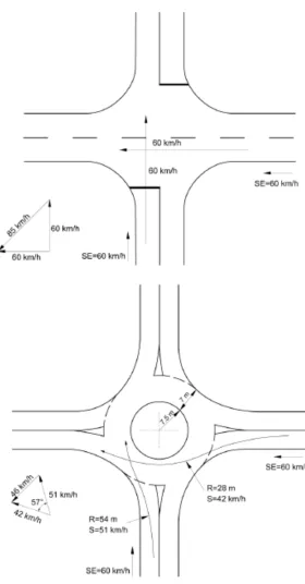
15 Figure 2 – Relative intersection speeds (Department Main Roads 2006)
16
2.2.1
Crash Types
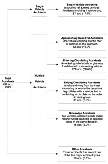
To date, the most extensive investigation in crashes on roundabouts within Australia is the Queensland Department of Main Roads roundabout study, Relationship between roundabout geometry and accidents, Arndt (1998). This study was taken across 100 roundabout totalling 492 major accidents where property damage exceeded $1000 and/or personal injury occurred which took data over a five-year period. From the study, the crash patterns can be separated into two types:
Single vehicle accident patterns: The majority of single vehicle crashes occurred as loss of control incidents leading to a collision with an object. This type of crash was largely contributed to the geometry of the roundabout. The study concluded that single vehicle accident rate appeared higher at sites with the following geometry
High absolute speed on the particular geometric element Large decrease in speed between geometric elements Curves when motorists use high values of side friction Long curves
Multi vehicle accident patterns: Multiple vehicle accidents were found to be largely attributed to major driver error in which they failed to observe another vehicle in enough time or at all. It appears that multi vehicle accident rate vehicles were relatively higher at sites where there were:
High relative speeds between vehicles Limited visibility to other vehicles
17 Figure 3 – Typical Roundabout crash types (Department Main Roads 2006)
18 objects. The other major crash type is rear end on approach. This crash type is directly related to the traffic volumes on the approach legs and is irrelevant to the scope of the project.
[image:19.595.76.477.189.586.2]To further investigate the crash types, the US department of Transport has conducted a similar study to the Arndt study and provided more detail on the crash type, breaking down the incidents into more categories. The results of their findings can be seen in the table below.
Figure 4 – Accident type breakdown (US Department of transport, 2000)
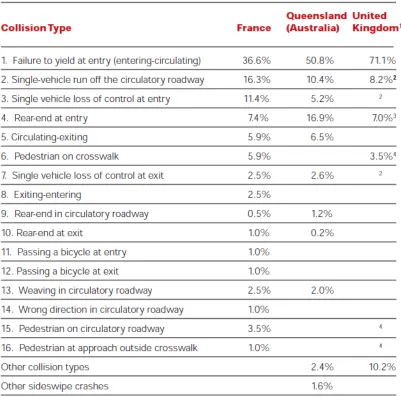
19 Figure 5 – Accident type diagram (US Department of transport, 2000)
20 The US department of Transport study provides information on the severity of single vehicle crashes. The report claims that:
“To reduce the severity of single vehicle crashes, special attention should be accorded to improving
visibility and avoiding or removing any hard obstacles on the central island and splitter islands in
both urban and rural environments. A French study (14) identified a number of major obstacles that
caused fatalities and injuries: trees, guardrail, concrete barriers, fences, walls, piers, sign or light
poles, landscaping pots or hard decorative objects, and steep cross-slopes on the central island. “
The report shows that there is a direct relationship between increased severities of single vehicle crashes when a major obstacle is hit. Safety barriers are directly mentioned to be causes of increased severity to the single vehicle crashes.
2.3
Design Methods and Standards for Roundabouts
Geometric design standards for roundabouts can vary significantly between countries and also nationally within Australia between state governing bodies. Within Australia the design of main roads is to adhere to the states governing road authority’s guidelines. Differing approaches to the design of roundabouts can provide insight to deficiencies that may be inherent to a particular design method or standards.
The following is a review of Australian based guidelines for roundabouts with the intention of highlighting differences in both design methodology and also geometric requirements.
2.3.1
Austroads Design for Roundabouts
Austroads is the association of Australasian road transport and traffic agencies. The purpose of Austroads is to improve Australian and New Zealand transport outcomes. The Austroads association is made up of the following members.
Roads and Maritime Services New South Wales Roads Corporation Victoria
Department of Transport and Main Roads Queensland Main Roads Western Australia
Department of Planning, Transport and Infrastructure South Australia Department of State Growth Tasmania
Department of Transport Northern Territory
21 New Zealand Transport Agency
Austroads purpose is to improve Australian and New Zealand transport by achieving the following objectives:
providing expert technical input to national road and transport policy development improving the practices and capability of road agencies
Promoting operational consistency by road agencies.
In relation to roundabout design, Austroads provide the ‘Guide to Road Design’ which is intended to provide designers with a framework that promotes efficiency in design and construction, economy and both consistency and safety for road users. Section 4B: Roundabouts, provides road designers and other practitioners with guidance on the geometric design of roundabouts. It covers design principles and procedures, and guidelines for all the key elements, thus enabling practitioners to develop safe and efficient layouts.
Austroads Guide to Road Design Part 4B: Roundabouts provides a design procedure for the design of roundabouts and guidance on the best practice for detailed design. Austroads states the following in relation to its design principles and procedures:
“This Guide uses the method of controlling speed of traffic entering roundabouts through the
geometry of the roundabout entry, rather than within the roundabout where restriction through
deflection requirements is essentially too late in the process of the driver negotiating the
roundabout.”
Austroads provides its overall principles that should be applied to achieve a safe and efficient
roundabout design. According to Austroads the principles are:
The roundabout should be clearly visible from the approach sight distance at the road operating speed in advance of the roundabout approach.
The number of legs should preferably be limited to four (although up to six may be used at an appropriately designed single-lane roundabout).
Legs should preferably intersect at approximately 90°, especially for multi-lane roundabouts. It is essential that appropriate entry curvature is used to limit the entry speed.
Entry speeds should be established after considering the types of users, e.g. cyclists and pedestrians that are expected to travel through the roundabout.
Exits should be designed to enable vehicles to depart efficiently.
22 The circulating roadway should be wide enough to accommodate the swept paths of the design vehicle/s plus clearance to kerbs for both through movements and right-turn movements.
Entering drivers must be able to see both circulating traffic and potentially conflicting traffic from other approaches early enough to safely enter the roundabout.
Sufficient entry, circulating and exit lanes should be provided to ensure that the roundabout operates at an appropriate level of service.
Austroads indicate that from a safety perspective the most important geometric considerations in controlling vehicle speeds through roundabouts are:
Adequate sight distance to enable drivers to: – easily identify the intersection as a roundabout and comprehend their required path through the layout
Observe the movements of other vehicles, cyclists and pedestrians travelling within and on the approaches to the roundabout
Observe an acceptable gap in the circulating traffic and enter in a safe manner.
The entry geometry should be designed to restrict drivers to a safe speed on entry to the roundabout.
Taking these into consideration the design procedure outlined by Austroads is as follows: Step 1: Assemble general design criteria.
Step 2: Identify site controls
Step 3: Establish area available, alignments and cross sections
Step 4: Select Central island radius and circulating carriageway width. Step 5: Draw Central Island and circulating carriageway in trial position.
Step 6: Draw trial entry and exit leg geometry for all legs including vertical including vertical alignments.
Step 7: Check the maximum entry path radii have been achieved.
Step 8: Check swept paths of the design vehicle for all traffic movements including the circulating carriageway
Step 9: Check that sight distance is satisfactory.
23
[image:24.595.125.463.494.729.2]Central island radius: Austroads indicates that a larger roundabout enables better entry geometry to be designed. This will lead to a reduction in entering vehicle speeds and also reduce the angle formed between the entering and circulating vehicle paths. Table 4.1 provides a guide for the selection of the central island radius.
Figure 6 – Minimum central island radius (Austroads 2015)
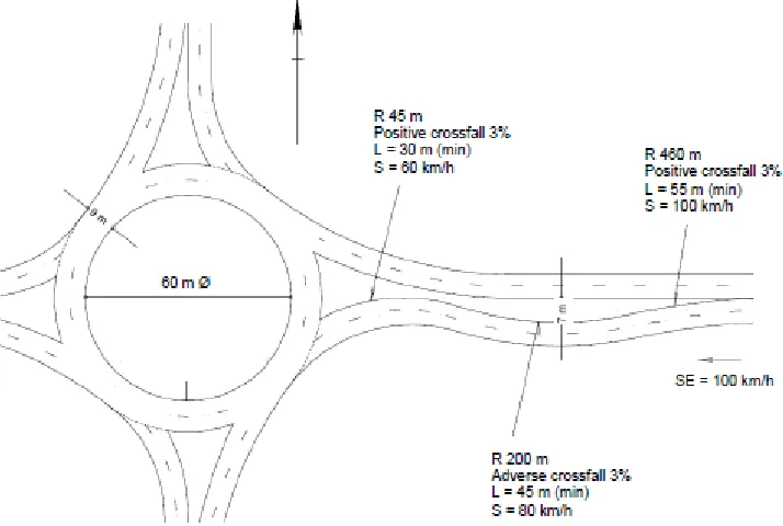
Approach and Entry Geometry: Austroads indicates the approach and entry geometry is the most important geometric parameter to be designed at roundabouts as it controls the speed of entering traffic and consequently the safety performance of the roundabout. The minimum treatment to be provided is a single entry curve. It is noted however that this treatment may not be suitable where the approach speed is high as it may potentially require an excessive decrease in speed leading to increased rate of single vehicle crashes. Reverse curves on approach can be used to slow the approaching vehicles in these situations.
24 Figure 8 – Alternative approach geometry (Austroads 2015)
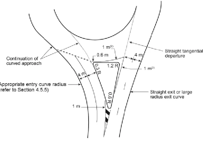
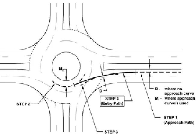
[image:25.595.122.479.75.315.2]To determine the entry path radius Austroads provides a guide to draw the entry path based on the roundabout arrangement. Provisions are given to design the three most common situations. These include single lane entry roundabouts, two lane entry where staying in the correct lane and two lane entry with cutting across lanes. In order to ensure deflection is appropriate, Austroads recommends using maximum values provided in the following table.
Figure 9 – Maximum entry path radius (Austroads 2015)
25 Figure 10 – Entry path construction (Austroads 2015)
Circulating carriageway: With an appropriate entry geometry selected, Austroads then provides recommend carriageway widths relating to central island radius and design vehicles. These recommended values however must be checked with a suitable vehicle swept path. This is required as the provided values may not be suitable for all possible roundabout geometry.
Exit Curves: Exit curves are designed to be as practicable for drivers to negotiate. Drivers should be able to accelerate from the circulating carriageway through the exit after being slowed by the entry curve. The design of the exit curve geometry should be completed with swept paths used for guidance.
2.3.2
NSW Supplement to Austroads
In NSW the design of roundabouts is to be in accordance with the Roads and Maritime supplement to Austroads Guide to Road Design. RMS supplements for section 4B of Austroads stipulates that the contents of section 4B be removed and replace with the Roundabouts Geometric Design Method published by RTA in 1997.
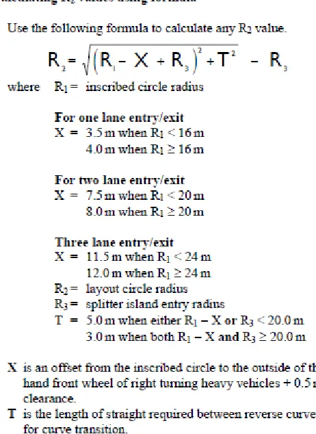
This guide does not present a set of principles or design methodology to be adhered to in the design of roundabouts. The guide provides a design method with numerical values to be calculated. The steps used to design a roundabout in accordance with RMS guidelines are as follows:
Step 1: Select radius and position of inscribed circle. Step 2: Determine radius of layout circle.
26 Step 4: Draw kerb line arc.
Step 5: Draw splitter island exit arc. Step 6: Draw exit kerb line arc. Step 7: Draw Central Island. Step 8: Complete design layout
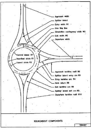
[image:27.595.143.458.246.698.2]The following diagram is provided within the guide to explain all of the geometric components:
27 When following the design method, the first design step is to determine an inscribed circle radius. The design of the inscribed circle is to be in relation to the number of entry lanes and the chosen design vehicle for the roundabout. The following table is provided to indicate the correct values:
Figure 12 – Minimum inscribed circle radii (RTA Austroads Guide Supplement, 2009)
It is not clearly indicated where the position of the centre of the roundabout is to be selected to suit site conditions. With an inscribed circle radius selected, an entry radius can be determined. This is again related to the number of entry lanes and design vehicle only. A Splitter island entry radius is selected based on lanes and entry design vehicle as follows:
Figure 13 – Minimum entry radius (RTA Austroads Guide Supplement, 2009)
28 Figure 14 – Layout circle calculation (RTA Austroads Guide Supplement, 2009)
29 Figure 15 – Circulating carriageway width (RTA Austroads Guide Supplement, 2009)
Centre island deflection is then checked for compliance. Deflection must be achieved through the roundabout. For a single lane roundabout design vehicle deflection templates can be used that must touch kerb lines on the entry/exit and also touch or cut across the central island.
2.3.3
Comparison of methods and standards:
When comparing the two design methods and principles of Austroads and RMS we can begin to see that there are several differences in their approach. While the RMS supplement provides a design method, it does not provide information on the principles of providing a safe roundabout or overall methodology behind design decisions.
30
2.4
Safety Barriers
When a safety barrier system is installed it is important to know that the barrier itself if a hazard and that they are installed when it is considered that impact with the barrier will be of reduced severity than the hazard it is intended to protect. This is outlined in Guide to Road Design Part 6: Roadside Design, Safety and Barriers:
“The purpose of road safety barrier systems is to shield vehicles from striking a hazard. However, it
is important to note that impacting a road safety barrier is a hazard for vehicle occupants although
usually less severe than impacting a rigid object in the road reserve (e.g. pole or tree). Road safety
barrier systems may increase the likelihood of vehicle impacts because they are longer than the point
hazards they shield and are closer to the traffic.”
From this it can be seen that barriers should only be installed in locations where their impact will be less severe than the hazard they are impacting
Barriers installed on main roads throughout Australia are dependent on the governing road authority’s approval. These are usually based of the authority’s approval of the manufacturer’s product specifications. When analysing how a barrier is impacted and if it is appropriately located the product specifications can be compared to evaluate design criteria. The following common barriers are currently approved for use in NSW.
2.4.1
Typical Barrier Installations
As this report is focused on NSW roads, the following barriers are the most common type of barriers located within roundabout environments in NSW. The following two main barrier systems represent the majority of barrier treatments at roundabouts.
G4 W-Beam Guardrail
The G4 guardrail is the most commonly installed safety barrier in Australia with many different manufacturers producing the product. The barrier system works on the rail acting as the rail separates from the posts absorbing energy while redirecting vehicles. Because the barrier works on having posts before and after the impact area providing support and redirection there is a point of need for installation. This means that the first length of the barrier is not effective as crash redirection.
31 typically is designed for a low impact angle. When being tested for approval of use, barriers are tested to a maximum angle of 25 degrees. This can be easily exceeded at an intersection arrangement. Therefore, when considering its effectiveness in the convex application to high angle impacts the NSW supplements to Austroads Guide to Road design provide the following information:
Figure 16 – Barrier installations at intersection (RTA Road Design Guide)
Modifications can be made to G4-W beam. Thrie beam is the most common modification. Thrie beam systems are similar to G4 guardrail and works on the same principle however it includes a larger rail. This extra rail increases the rigidity to the barrier. This makes the barrier stiffer and provides less deflection during collision’s however this will be causing an increased severity to the crash.
Type F concrete safety barrier: This is a permanent rigid safety barrier. This means that there is no deflection within the system during collisions. Rigid barriers have a far more severe impact however are used in restricted areas where hazards are close to the roadway. The primary function of Type F is as a re-directive barrier. Because of this, rigid concrete barriers are only suitable for impact angles of up to 15 degrees. Larger impacts are effectively similar to colliding with a concrete wall.
32 minimum radiuses of installation. Wire rope safety barriers use tension within the strands of wire to absorb energy and redirect the vehicles as they impact.
2.4.2
Severity Index of Barriers
In road design the severity index (SI) is used to measurement expected severity of an impact with an object. The severity index is a weighted scale of 0 to 10, where 0 is no impact and 10 being a likely fatality. These are based on average expected outcomes and not worst case. Queensland’s Transport for Main Roads provides costs associated with each SI as determined by the Australian Bureau of Statistics (in 2001 dollars) and Austroads has provided the following values based on this with costs scaled to 2008 values.
Figure 17 – Severity index relative cost (Austroads 2016)
33 Figure 18 – Severity Indices of barriers (RTA Road Design Guide, 1996)
34 Figure 19 – Severity indices (Austroads Guide to Road Design, 2009)
35
3
Methodology
Safety barrier systems are deployed to reduce the severity of crashes which cause cannot be eliminated. This will be the focus of the project as it will investigate the causes of their implementation to determine if it is justified and the effectiveness at reducing the severity where possible. To achieve this, the analysis will take the form of a case study. In consultation with local road authorities, known problem sites with differing conditions will be chosen and assessed in the following outlined ways.
3.1
Literature review
As part of this study, literature was reviewed from national and international sources to aid in the understanding of the following:
Roundabout geometric design methods and best practice used nationally and internationally Crash types associated with roundabouts
Comparison of available safety barriers
The desired application of safety barriers and their implementation in roundabout environments
The review was completed to provide an understanding of the elements that can be attributed to crashes within a roundabout environment and how they could interact with the implementation of safety barriers in that environment. Providing a variety of sources was important to determine if there are any potential points of difference or oversights not considered locally.
3.2
Site Assessments
Research into the direct implementation of barriers on roundabouts is fairly limited. In recent times it can be seen with government funded blackspot programs, implemented in response to high crash rates. A number of sites had implemented safety barriers in response to crashes. Analysis of these sites and similar untreated sites would allow for a review of their performance and if it had or has the potential to effectively resolved the safety issues at the location.
3.2.1
Site Selection Criteria
When selecting a site for assessment the following criteria are required: Site must be located within NSW
Crash history must be available through CrashLink.
36 Site must be in a reasonable and practical location to travel to
3.2.2
Site Visit
A site visit will be conducted on all sites selected for assessment. The purpose of the site visit is to gain a road user perspective of the site. Ideally the site visit will be undertaken before any desktop analysis is performed to identify any road deficiency that may be perceived by a road user.
Photographs and video of the sites are to be taken for reference later in review. Key points to be identified in the site visit are to identify and safety hazards within the roundabout location. The context of the roundabout and how it connects to the local road network should be identified. Importantly road user behaviour should be noted to see how road users are negotiating the roundabout. Elements of the road user’s behaviour such as entry speed, braking and indicating should be observed.
3.2.3
Geometric Review
A desktop review of the location will be undertaken of the site beginning with a geometric analysis of the site. The actual geometry will be recorded and compared against the acceptable values shown in both Austroads and NSW supplement.
The geometry of the roundabout will be analysed in the separate components of the roundabout. The following components will be recorded and compared:
Central Island Radius Entry Curve radius Entry Width
Curve entry design speed Circulating lane widths Departure Radius Departure Width Deflection
37
3.2.4
Crash Data Analysis
A 15-year crash history will be analysed for each site. Where possible, sites will be checked for any significant changes in geometry or roadside environment over the 15-year period which may alter the crash data. RMS CrashLink data recorded by police and self-reporting of incidents will be utilised to review the crash history of the site. Crash data used can be seen in Appendix C.
3.2.5
Data review
Crash data and geometric analysis results will be correlated and compared. This is to identify and any trends or anomalies within the data set. The data review will form the basis of the results. Overall trends will give numerical data behind any deficiencies either with geometric properties or also with barrier performance where possible.
3.2.6
Data limitations
The data being used from crash link has its limitations. In general, the information recorded in the crash data is only recorded by police if they attended the crash. Some of the data is also based on self-reporting and cannot be accurately verified.
The data recorded for crash link has limited information and generally will have a crash type, direction travelling and movements being taken. Information on injuries and fatalities are also included. Speed and fatigue are indicated however this is not based on accurate sources so will be excluded from consideration in the analysis.
The analysis of the geometry of the sites is based off aerial photography.
3.3
Site Overviews
3.3.1
Site 1 – Crystal Street, Forresters Beach
38 Figure 20 – Pacific Highway, Crystal Street intersection
The roundabout has dual approaches on all legs however the circulating carriageway acts as singular lane for all except the eastbound movement along the Pacific Highway.
This site has existing barriers installed on the southern through lane of the Pacific Highway. The eastern departure also features a safety barrier for a short length. It should be noted that this barrier has a terminal that starts adjacent to the start of the departure radius. The terminal itself appears to be an ET2000 terminal which are rated for head on impacts however this is not ideal for performance or safety to vehicles. From observing historical photographs, the site appears to of been unchanged since 2007 in terms of barriers. A considerable sized apron is used on this roundabout to provide additional deflection and tracking where needed. The raised central island is quite small and from a driver’s perspective the apron could be easily cut to increase speed through the roundabout. This is most apparent on the westbound movement. Considerable wear can be seen on the apron where this appears to happen.
3.3.2
Site 2 – Brittania Drive, Wyong
39 comprised of local traffic servicing the surrounding suburbs. The Pacific Highway is a heavy vehicle route with it being designated for use by 25m B-Doubles. The Pacific Highway has a speed limit of 70km/h and Brittania Drive has a speed limit of 50km/h.
Figure 21 – Pacific Highway, Brittania Drive intersection
The site features an unusual roundabout layout to maximise efficiency of the pacific highways dominant movement being from south to east. This has a slip lane from the east to the south essentially removing this movement from the circulating lane and gap acceptance of the roundabout. The roundabout has dual approaches however the circulating lane is only single lane except for the west to east movement from Brittania Drive to Wyong Road. The only safety barriers on the site are on the Eastern leg of the roundabout and are the extensions of the bridge barriers adjoining the site.
3.3.3
Site 3 – Johns Road, Wadalba
40 The speed limit on the Pacific Highway is 70km/h with Johns Road having a limit of 50km/h.
Figure 22 – Pacific Highway, Johns Road intersection
Johns Road roundabout is dual approach and departure for the through movements on the Pacific Highway. Johns road has only minor traffic flows that enter from the eastern approach. The geometry of the western approach is noticeably poor. A large rigid concrete barrier runs for the entire east to west length of the site and a w-beam barrier is located adjacent to the west to north leg. From historical photographs these barriers have been installed and unchanged since 2007. There is noticeable wear on the rigid concrete barrier.
3.3.4
Site 4 – Pindarri Avenue, Berkley Vale
41 Figure 23 – Wyong Road, Pindarri Avenue intersection
The roundabout at Pindarri Avenue has dual approaches on all legs. The circulating lanes are two lanes for the entire roundabout. The circulating lanes on the roundabout appear to be under used as the current layout does not allow movements to utilise the outer circulating lane on the north and south circulating sections. The east departure is narrow for two lanes and merges quickly. The roundabout is relatively free flowing with north south movements dominating the traffic flow.
A long w beam barrier is adjacent to the southern approach and continues through the roundabout to past the northern departure. A barrier is installed on the south east corner of the roundabout. This barrier has only recently been installed within the last 12 months. When accounting for barriers in previous crashes this will be considered as not present.
3.3.5
Site 5 – Chelmsford Road, Charmhaven
42 vehicle route with 25m B-Doubles permitted to use the section of road. Chelmsford Road and Lake Haven Drive have 50km/h speed limits.
[image:43.595.105.493.149.469.2]Details of site
43
3.3.6
Site 6 – Geoffrey Road, Chittaway Bay
[image:44.595.154.444.201.602.2]Site 6 is located at the intersection of Geoffrey Road and Wyong Road. The intersection has 3 legs with the predominant movement being the through movement along Wyong Road. Geoffrey Road is a local collector road that only has local traffic utilising it. Wyong Road is a designated heavy vehicle route with 25m B-Doubles utilising the route. Wyong Road has a speed limit of 70km/h with Geoffrey Road having a speed limit of 50km/h.
44
3.3.7
Site 7 – Mingara Drive, Tumbi Umbi
[image:45.595.87.513.202.540.2]Site 7 is located at the intersection of Mingara Drive, Tumbi Creek Road and Wyong Road at Tumbi Umbi. The roundabout has four legs. Wyong Road is a designated heavy vehicle route with 25m B-Doubles utilising the route. Wyong Road is a 70km/h road. Mingara Drive is a 50km/h road and provides access to a large commercial area with a relatively high traffic flow. Tumbi Creek road is a local collector road.
45
3.3.8
Site 8 – Cresthaven Avenue, Bateau Bay
[image:46.595.176.420.202.489.2]Site 8 is located at the intersection of Cresthaven Avenue and The Central Coast Highway at Bateau Bay. Along the highway there is a posted speed limit of 60km/h with a 50km/h speed limit on Cresthaven Avenue. The Central Coast Highway is a designated heavy vehicle route with 25m B-Doubles utilising the route. The roundabout has three legs and the through movement along the highway is the dominant movement.
46
4
Results and Analysis
The results for each individual site are discussed in the following sections. Combined correlated data results are discussed in section 5.
The individual site analysis is summarised in two tables with results discussed. The first table is a geometric analysis summary. This will show all of the determined geometric values and use a colour index to identify compliance. The colours can be referred to the table below:
Table 1 – Geometric Compliance Index
Geometric Compliance Index Compliant with All Standards
Complaint with RMS supplements only Compliant with Austroads Standards only Non‐Compliant
The second table shown for each site is a crash summary table. This table will identify in what direction the vehicle was traveling and the turning movement being undertaken when the crash occurred where attainable from the crash data. The number of crashes and injuries will be shown as well as a colour referenced risk rating based on the relative non-conformances over those movements. The coverage through the movements will be recorded as well. This will be separated into full barrier coverage, partial barrier coverage and nil barrier coverage. The following table identifies the coloured risk rating system used in the analysis:
Table 2 – Roundabout Manoeuvre Risk Assessment
Roundabout Manoeuvre Risk Assessment
Low risk, geometry conforms to standards
Minor Minor deviations from standard with minimal
notable safety implications
Major
Major deviations from standard or multiple
non‐conformances with compounding safety
47
4.1
Site 1 – Crystal Street, Forresters Beach
Geometric analysis: The geometric analysis was conducted and summarised below. Table 3 – Site 1 Geometric Analysis Summary
Component RMS
Standard
Austroads
Standard
Recorded Site Geometry
Notes
NORTH EAST SOUTH WEST
Central
Island
Radius (m)
7.5 18 9.4
Entry Curve
Radius (m) 100 max <55 NA 52 52 122
Entry Curve
Design
Speed
(km/h)
NA 38 38 58
Entry Width
(m)
8 (double
approach)
4.5 (single
approach)
Turn path
(min 5m
single lane
arterial
road)
NA 8.5 8 8
Circulating
Lane Width
(m)
11.5 (double
lane) 8.2
(single lane)
11 (double
lane) 8.2
(single lane)
9.5 5.7 5.3 5.7
Mountable apron
provides
additional width of
2.5m for tracking
Departure
Radius (m)
> Entry
radius
Straight or
as large as
possible
NA 110 132 130
Departure
Width (m)
8 (double
departure)
5.2 (single
departure)
Based on
turn paths
only
NA 7 4.8 4.5
Reduced values
acceptable for
local roads
Deflection
RMS
method on
through
movement
Austroads,
approach
stay in lane
method
48
[image:49.595.72.443.136.545.2]Crash Movement Analysis: The detailed 15-year crash report was used to create the following crash summary table.
Table 4 – Site 1 Roundabout Manoeuvre Crash Analysis
Movement Information Approach Direction
North East South West
Left Turn
Crashes 0 0 0 0
Injuries 0 0 0 0
Geometry
compliance Minor
Barrier
installation Partial Full
Through
movement
Crashes 0 8 0 7
Injuries 0 4 0 1
Geometry
compliance Minor Major
Barrier
installation Full Partial
Right turn
Crashes 0 0 1 0
Injuries 0 0 1 0
Geometry
compliance Minor Major
Barrier
installation Partial Partial
Unknown
movement
Crashes 0 0 0 0
Injuries 0 0 0 0
Discussion: On review Crystal Street has a relatively good geometric design. The westbound approach is the only leg of the roundabout with major departures. On approach from the west, it is possible for vehicles to drive almost straight through the intersection if they traverse the concrete apron surrounding the centre island.
49 The Eastbound approach has a relatively good approach however at the time of the site visit it felt as though the single curve approach did not adequately control approach speed on its own and it had a noticeable manoeuvre required to exit the roundabout from the circulating lane in this direction. Examination of the geometric and crash data showed that the two approaches were performing similar in terms of crash history. Interestingly although the westbound approach had a significantly more deficient geometry it had resulted in fewer injuries. This site was greatly over represented with 54% of crashes at the site being off carriageway crashes.
50
4.2
Site 2 – Brittania Drive, Wyong
Geometric analysis: The geometric analysis was conducted and summarised below. Table 5 – Site 2 Geometric Analysis Summary
Component RMS
Standard
Austroads
Standard
Recorded Site Geometry
Notes
NORTH EAST SOUTH WEST
Central
Island
Radius (m)
4.7 12 14.8
Entry Curve
Radius (m) 100 max <55 NA 69 76 46
Entry Curve
Design
Speed
(km/h)
NA 44 46 36
Entry Width
(m)
8 (double
approach)
4.5 (single
approach)
Turn path
(min 5m
single lane
arterial
road)
NA 5 7.6 8.1
Circulating
Lane Width
(m)
11.5 (double
lane) 8.2
(single lane)
11 (double
lane) 8.2
(single lane)
10.3 4.4 4.4 4.4
Large Painted
islands for tracking
increase width
Departure
Radius (m)
> Entry
radius
Straight or
as large as
possible
NA 48 75 24
Departure
Width (m)
8 (double
departure)
5.2 (single
departure)
Based on
turn paths
only
NA 8.5 7.5 7.8
Reduced values
acceptable for
local roads
Deflection
RMS
method on
through
movement
Austroads,
approach
stay in lane
method
51
[image:52.595.69.401.133.543.2]Crash Movement Analysis: The detailed 15-year crash report was used to create the following crash summary table.
Table 6 – Site 2 Roundabout Manoeuvre Crash Analysis
Movement Information Approach Direction
North East South West
Left Turn
Crashes 0 0 1 0
Injuries 0 0 1 0
Geometry
compliance Minor
Barrier
installation Nil
Through
movement
Crashes 0 0 0 1
Injuries 0 0 0 0
Geometry
compliance Minor Minor
Barrier
installation Nil Nil
Right turn
Crashes 0 1 9 1
Injuries 0 1 6 1
Geometry
compliance Major Minor
Barrier
installation Partial Nil
Unknown
movement
Crashes 0 1 3 0
Injuries 0 0 2 0
Discussion: Brittania Drive was suggested for analysis because of a high occurrence of severe of carriageway crashes. When analysing the geometry and crash history the eastern approach to left turn was excluded as it was controlled by a separated slip lane. This was not a standard
The Southern approach turning right was noted as the significant movement at the roundabout. On review this does not meet approach geometry requirements for deflection based on Austroads Standards but is largely compliant with RMS supplements.
52
53
4.3
Site 3 – Johns Road, Wadalba
Geometric analysis: The geometric analysis was conducted and summarised below. Table 7 – Site 3 Geometric Analysis Summary
Component RMS
Standard
Austroads
Standard
Recorded Site Geometry
Notes
NORTH EAST SOUTH WEST
Central
Island
Radius (m)
4.7 18 11.9
Entry Curve
Radius (m) 100 max <55 63 Straight NA 37
Entry Curve
Design
Speed
(km/h)
42 70 0 32
Entry Width
(m)
8 (double
approach)
4.5 (single
approach)
Turn path
(min 5m
single lane
arterial
road)
8.1 8.1 NA 8.1
Circulating
Lane Width
(m)
11.5 (double
lane) 8.2
(single lane)
11 (double
lane) 8.2
(single lane)
6.3 10.3 11 6.5
Departure
Radius (m)
> Entry
radius
Straight or
as large as
possible
54 54 NA 48
Islands allow for
tracking on
departure radius
Departure
Width (m)
8 (double
departure)
5.2 (single
departure)
Based on
turn paths
only
7.2 4.3 NA 6.9
Islands allow for
tracking on
departure radius
Deflection
RMS
method on
through
movement
Austroads,
approach
stay in lane
method
54
[image:55.595.70.402.134.544.2]Crash Movement Analysis: The detailed 15-year crash report was used to create the following crash summary table.
Table 8 – Site 3 Roundabout Manoeuvre Crash Analysis
Movement Information Approach Direction
North East South West
Left Turn
Crashes 0 1 0 1
Injuries 0 0 0 0
Geometry
compliance Minor Single Minor
Barrier
installation Nil Full Full
Through
movement
Crashes 0 0 0 0
Injuries 0 0 0 0
Geometry
compliance Major Minor
Barrier
installation Full Partial
Right turn
Crashes 2 0 0 0
Injuries 1 0 0 0
Geometry
compliance Minor Minor Single
Barrier
installation Partial Full Partial
Unknown
movement
Crashes 0 0 0 0
Injuries 0 0 0 0
Discussion: Johns Road had considerable non-conformances. It should also be noted that the site visit indicated that the vertical geometry was significant in restricting sight on approaches to Johns Road. It can be seen in the detailed crash reports that off carriageway crashes are significant at the site and this appears to be due to substandard geometry. The detailed crash summary indicates that from 9 off carriageway crashes a resulting 5 injuries occurred. Due to limitations in the reporting however the majority of crashes could not be accurately associated to a turning movement.
56
4.4
Site 4 – Pindarri Avenue, Berkley Vale
Geometric analysis: The geometric analysis was conducted and summarised below. Table 9 – Site 4 Geometric Analysis Summary
Component RMS
Standard
Austroads
Standard
Recorded Site Geometry
Notes
NORTH EAST SOUTH WEST
Central
Island
Radius (m)
4.7 18 14.9
Entry Curve
Radius (m) 100 max <55 40 43 46 NA
Entry Curve
Design
Speed
(km/h)
33 35 36 NA
Entry Width
(m)
8 (double
approach)
Turn path
(min 5m
single lane
arterial
road)
6.7 7.1 6.7 NA
1.4m Cycle
lane/shoulder
adjacent
Circulating
Lane Width
(m)
11.7 (double
lane) 8.9
(single lane)
11 (double
lane) 8.2
(single lane)
9.9 10.1 10 9.7
1.4 cycle lanes
adjacent to
through circulating
carriageway
Departure
Radius (m)
> Entry
radius
Straight or
as large as
possible
67 55 94 NA
Departure
Width (m)
8 (double
departure)
5.2 (single
departure)
Based on
turn paths
only
7 7 6.8 NA 1.4m cycle lane in
shoulder
Deflection
RMS
method on
through
movement
Austroads,
approach
stay in lane
method
57
[image:58.595.70.399.133.544.2]Crash Movement Analysis: The detailed 15-year crash report was used to create the following crash summary table.
Table 10 – Site 4 Roundabout Manoeuvre Crash Analysis
Movement Information Approach Direction
North East South West
Left Turn
Crashes 0 0 0 0
Injuries 0 0 0 0
Geometry
compliance
Barrier
installation Nil Nil
Through
movement
Crashes 14 0 14 0
Injuries 1 0 1 0
Geometry
compliance Major Major
Barrier
installation Nil Full
Right turn
Crashes 0 0 3 0
Injuries 0 0 3 0
Geometry
compliance Major Major
Barrier
installation Full Partial
Unknown
movement
Crashes 0 0 0 0
Injuries 0 0 0 0
Discussion: The intersection at Pindarri Avenue is noticeably quick for a roundabout environment. Although it can be seen that approach kerb radiuses are adequate, the roundabout relies on deflection within the roundabout and departure movement to reduce speed.
58 It is significant to note that the south and north through movements are similar in terms of geometry however the southern approach through movement is fully protected by safety barriers in comparison to the northern through movement. This is unexpectedly not represented with a change in the percentages of crashes resulting in injuries.
As with other sites it is again noted that right turn movements are over represented in terms of injuries per off carriageway crash.
59
4.5
Site 5 – Chelmsford Road, Charmhaven
Geometric analysis: The geometric analysis was conducted and summarised below. Table 11 – Site 5 Geometric Analysis Summary
Component RMS
Standard
Austroads
Standard
Recorded Site Geometry
Notes
NORTH EAST SOUTH WEST
Central
Island
Radius (m)
4.7 18 14.9
Entry Curve
Radius (m) 100 max <55 22 40 46 87
Entry Curve
Design
Speed
(km/h)
25 33 36 49
Entry Width
(m)
8 (double
approach)
4.9 (single
approach)
Turn path
(min 5m
single lane
arterial
road)
6.9 6.7 5.9 6.5
Circulating
Lane Width
(m)
11.7 (double
lane) 8.9
(single lane)
11 (double
lane) 8.2
(single lane)
9.4 9.4 9.1 9
Departure
Radius (m)
> Entry
radius
Straight or
as large as
possible
180 72 300 56
Departure
Width (m)
8 (double
departure)
5.2 (single
departure)
Based on
turn paths
only
8.2 7.9 8.1 7.7
Reduced values
acceptable for
local roads
Deflection
RMS
method on
through
movement
Austroads,
approach
stay in lane
method
60
[image:61.595.72.443.136.545.2]Crash Movement Analysis: The detailed 15-year crash report was used to create the following crash summary table.
Table 12 – Site 5 Roundabout Manoeuvre Crash Analysis
Movement Information Approach Direction
North East South West
Left Turn
Crashes 0 1 0 0
Injuries 0 0 0 0
Geometry
compliance Minor
Barrier
installation Nil Nil Nil Nil
Through
movement
Crashes 8 0 10 0
Injuries 1 0 2 0
Geometry
compliance Major Minor Major Minor
Barrier
installation Nil Nil Nil Nil
Right turn
Crashes 0 0 1 0
Injuries 0 0 0 0
Geometry
compliance Minor Minor
Barrier
installation Nil Nil Nil Nil
Unknown
movement
Crashes 0 3 0 0
Injuries 0 2 0 0
Discussion: This site is a four-legged roundabout with significantly comparable traffic flows on three legs. Noted at the site visit was that the Eastern leg has significant vertical grade on its approach. This significantly reduces vehicle speeds and restricts sight distance. The north south movements were difficult to assess when attending the site visit due to heavy traffic conditions. The site has also recently had new safety barriers and approach treatments installed.
The assessment of the geometry and this site was based on previous aerial photography that more accurately represented the site conditions over the crash data period.
61 north is compliant to RMS supplements however it can be noted that this roundabout largely depends on deflection achieved within the roundabout and departure to control speed. The heavy off carriageway crash movements are on these north south movements and appear to be related to this.
62
4.6
Site 6 – Geoffrey Road, Chittaway Bay
Geometric analysis: The geometric analysis was conducted and summarised below. Table 13 – Site 6 Geometric Analysis Summary
Component RMS
Standard
Austroads
Standard
Recorded Site Geometry
Notes
NORTH EAST SOUTH WEST
Central
Island
Radius (m)
4.7 18 9.8
Entry Curve
Radius (m) 100 max <55 58 28 60 NA
Entry Curve
Design
Speed
(km/h)
40 28 41 NA
Entry Width
(m)
8 (double
approach)
4.9 (single
approach)
Turn path
(min 5m
single lane
arterial
road)
6.9 6.2 6.9 NA
1.4m Cycle
lane/shoulder
adjacent
Circulating
Lane Width
(m)
11.5 (double
lane) 8.2
(single lane)
11.5 (double
lane) 8.9
(single lane)
6.5 9.4 6.6 9.8
1.4m Cycle
lane/shoulder
adjacent
Departure
Radius (m)
> Entry
radius
Straight or
as large as
possible
Straight 56 150 NA
Departure
Width (m)
8 (double
departure)
5.2 (single
departure)
Based on
turn paths
only
7 5.7 7 NA
Reduced values
acceptable for
local roads
Deflection
RMS
method on
through
movement
Austroads,
approach
stay in lane
method
63
[image:64.595.73.446.130.548.2]Crash Movement Analysis: The detailed 15-year crash report was used to create the following crash summary table.
Table 14 – Site 6 Roundabout Manoeuvre Crash Analysis
Movement Information Approach Direction
North East South West
Left Turn
Crashes 0 0 0 0
Injuries 0 0 0 0
Geometry
compliance <