Contents lists available atScienceDirect
Composite Structures
journal homepage:www.elsevier.com/locate/compstruct
Three-dimensional woven carbon
fi
bre polymer composite beams and plates
under ballistic impact
Paul Turner
a,b, Tao Liu
a,b,⁎, Xuesen Zeng
c, Kevin Brown
daCentre for Structural Engineering and Informatics, Faculty of Engineering, University of Nottingham, University Park, Nottingham NG7 2RD, UK bComposites Research Group, Faculty of Engineering, University of Nottingham, University Park, Nottingham NG7 2RD, UK
cUniversity of Southern Queensland, Centre for Future Materials, Toowoomba, Queensland 4350, Australia dR&T and Composite Fan Impact Group, Rolls-Royce plc, Derby DE24 8BJ, UK
A R T I C L E I N F O
Keywords:
3D woven composites Ballistic impact experiment Multi-hit
Finite element Failure mechanism
A B S T R A C T
Clamped rectangular orthogonal 3D woven carbon composite beams under ballistic impact at a velocity range
⩽ ⩽
− v −
60 ms1 190 ms
0 1were investigated in order to understand the damage mechanisms within the material and the role of through-the-thickness (TTT) reinforcement. Experimental tests revealed three distinct categories of beam response: (i) low velocity impacts (v <110 ms−
0 1) which featured projectile rebound, with dominant matrix cracking and localisedfibre fracture, (ii) medium velocity impact (110 ms−1⩽v <148 ms−
0 1) which ex-hibited a stretch-deformation dominated failure mechanism, and (iii) higher velocity impacts (v ⩾148 ms−
0 1)
which resulted in projectile penetration, combined with longitudinalfibre fracture at the centre of the sample. Finite element (FE) simulations were conducted to understand the experimental outcomes, which showed
suf-ficientfidelity and captured the three distinct beam response regimes. The presence of the TTT-reinforcement can suppress the inter-laminar matrix crack propagation and increase the material ballistic impact resistance for low velocity impact and high velocity impact. However, for medium velocity impact, the in-planefibre fracture surface was found to be at the locations of TTT-reinforcement. This may suggest that the TTT-reinforcement creates weak points for the stretch-deformation dominated failure mechanism. The verified FE simulations were conducted to predict the multi-hit ballistic impact limit surfaces for the clamped circular 3D woven composite plates, and for the equivalent laminate composite without the presence of the TTT reinforcement. The numerical results suggested the presence of TTT reinforcement could improve the multi-hit ballistic resistance of the composite plates for multi-hit scenarios where the initial impact is 50%–95% of the ballistic limit of the plates.
1. Introduction
The dynamic impact of foreign objects upon aircraft structures is of great concern and is often a critical load case for design engineers to consider. Common sources of impact events include bird strikes, hail stones and runway debris. Thefirst of these impact types is classified as soft body impact, the last two are impact of solid ‘stiff’ projectiles. During take-offand landing, aircrafts can receive impact events from runway debris at velocities of up to approximately 250 ms−1[9,11]. Carbonfibre reinforced composite materials have been widely used in aircraft structures owing to their high specific stiffness and strength as well as low coefficient of thermal expansion. The impact of runway debris can cause damage to thefibre reinforcement, the matrix and can cause delamination damage within unidirectional (UD) laminate com-posites.
Woven textile composites have seen extensive development in the
recent years due to their inherent protection against inter-laminar crack propagation; and their ease of manufacturing of complex shapes[10]. In particular, nearly net-shape 3D woven composite textiles have gen-erated much interest within industry. The 3D weaving process, not too dissimilar to conventional loom-based textile weaving, has the potential for low cost automation and high volume production. Research into 3D woven composite materials undertaken over the past two decades has revealed the advantages of 3D woven composites in comparison to UD-laminate or 2D woven composites, see Mouritz et al.[10]. For example, the inter-laminar fracture toughness values of 3D woven composites have been reported in the literature up to values as high as 7000 J/m2, with far less reductions of in-plane material properties as is common with 2D woven structures[1]. For soft body impact, Turner et al.[13] experimentally and numerically investigated the dynamic behaviours of clamped orthogonal 3D woven carbon composite beams under metal foam projectile soft impact at velocities up to 270 ms−1. The results
https://doi.org/10.1016/j.compstruct.2017.10.091
Received 20 August 2017; Received in revised form 21 October 2017; Accepted 27 October 2017
⁎Corresponding author at: Centre for Structural Engineering and Informatics, Faculty of Engineering, University of Nottingham, University Park, Nottingham NG7 2RD, UK. E-mail address:[email protected](T. Liu).
Available online 08 November 2017
0263-8223/ © 2017 The Authors. Published by Elsevier Ltd. This is an open access article under the CC BY license (http://creativecommons.org/licenses/BY/4.0/).
suggested that the 3D woven carbon composite beams had significantly less in-plane damage and delamination damage compared to the equivalent UD-laminate beams.
However, there is a distinct shortage of studies within the literature regarding the comparison of the ballistic impact limit between 3D woven and equivalent UD-laminate or 2D woven materials. Here, the ballistic limit is defined as the velocity at which the predicted material response changes from projectile rebound to projectile penetration. Comparisons between 3D and 2D woven plates provided a range of conclusions. An experimental study on the ballistic impact response of clamped fibre reinforced composite plates recorded approximately a 14% increase in 3D woven carbon composites compared to 2D woven carbon composites [15], although no mechanistic reasoning was pro-vided. A different study, by impacting clamped samples with a 0.30 calibre fragment simulating projectile, recorded a 5% reduction in ballistic limit for the orthogonal 3D woven composite in comparison with a 2D plain weave carbon composite[16]. A numerical study has been conducted by Ghosh and De[4]to identify how the through-the-thickness (TTT) reinforcement in the orthogonal 3D woven composite can influence the ballistic response of a composite plate. They gave a detailed account on how the TTT-reinforcement can modify the local response of the composite material, showing increased propagation of damage along the direction of TTT reinforcement. However, the da-mage and stress wave propagation within the material was only studied in detail for the initial stages of the impact event and only at the lo-cation within the immediate vicinity of the projectile strike position. The work presented here attempts to characterise the global structural response of the 3D woven composite beams and plates under high ve-locity ballistic impact, focusing on projectile velocities close to the ballistic limit of the composite plates. By explicitly modelling the geo-metry of the TTT reinforcement, and by modelling the entire sample during the impact event, it is possible to investigate the role of TTT reinforcement during ballistic impact loading.
Aerospace structures may be subjected to multiple impact events. For example, upon inspection of the reinforced carbon-carbon compo-site plates from a single flight mission of the spaceship Discovery, a total of 176 different impact damage sites were recorded. Even though the structural integrity to withstand multiple impacts is critical in the design of protective systems, the current literature generally shies away from such investigations. One difficulty in conducting multi-hit impact studies is the method of characterisation. A commonly performed method of characterisation is the recording of damage within the plate. This can be either through visual inspection, c-scan, energy absorption within the material, or compression after impact (CAI) testing. Karthikeyan et al.[6]proposed a new method in which multi-hit sin-gular-point characterisation of materials is realised through a ballistic limit interaction map between primary and secondary impact events. It was proven to be a useful approach in determining the influence of primary impacts on the response of a secondary impact for a wide range of impact velocities. The initial impact causes damage within the plate and modifies the response during a secondary impact event. A combi-nation of the primary and secondary impacts results in either pene-tration or rebound of the projectile. The shape of the boundary surface between these two binary events is related to inherent material prop-erties. The methodology has been employed for a numerical study of the multi-hit damage characterisation of 304 stainless steel plates by Russell [12]. In the present paper, the methodology will be used to characterise the multi-hit behaviour of orthogonal 3D woven carbon composite plates, alongside with that of the equivalent cross-ply lami-nate plates for comparison.
The paper is organised as follows. In Sections 2 and 3, the de-scription of the experimental protocol and the numerical modelling for ballistic impact events is presented. In Section4, the ballistic impact upon clamped orthogonal 3D woven composite beam samples is pre-sented based on both experiment and numerical modelling. The nu-merical model is validated by the back-face deflection and damage
mechanisms from the experimental testing. Both experiment and nu-merical results will be used to develop understanding on the role of the TTT reinforcement during ballistic impact loading. In Section 5, clamped circular orthogonal 3D woven carbon composite plates under multi-hit ballistic impact is presented based on the verified numerical simulations.
2. Experimental study
2.1. Material
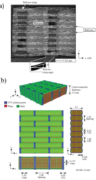
An orthogonal 3D woven carbonfibre epoxy resin composite ma-terial was manufactured using the method described by Turner et al. [13], summarised as follows. Thefibre reinforcement consisted of 7μm diameter AKSACA A-38 carbonfibre tows, with 6 Kfilaments for the warp and weft tows, and 3 Kfilaments for the through-the-thickness reinforcement tows. The reinforcement fabric had a binder-to-warp-stack-ratio of 1:2 (i.e. each binder tow is separated by two vertical stacks of warp tows). Gurit Prime 20LV epoxy resin, with a slow hardener to resin ratio by weight of 26:100, was used to produce the composite materials. Resin injection within a steel mould tool followed the standard vacuum infusion methodology. The final cured areal density of the composite material was 5210 g m−2. Cross sectional microscopic images of the cured composite, such as the one presented inFig. 1(a), were used to measure the average values for dimensions of thefibre architecture.Fig. 1(b) presents sketches of the fibre archi-tecture. The material contained an alternating stack of 9 weft layers and 8 warp layers. Top and bottom tows were orientated along the weft direction, and were the only tows with an induced crimp due to loca-lised influence of the TTT-reinforcement. As shown inFig. 1(a), the induced crimp angle was 7° from the horizontal.
As shown inFig. 1(b), the average width and thickness of warp tows were 1.70 mm and 0.177 mm, respectively. Average width and thick-ness of weft tow were 1.40 mm and 0.230 mm, respectively. Average width and thickness of TTT-reinforcement were 0.5 mm and 0.1 mm, respectively. Spacing between TTT-reinforcement was 3.48 mm. Total fibre volume fraction for the cured composite was 0.55. The towfibre volume fractions, i.e. the ratio of the area offibres into the area of the tow, were 0.785, 0.692, and 0.795 for warp, weft, and TTT-reinforce-ment tows, respectively. A co-ordinate system is defined inFig. 1(b) and utilised throughout this paper; the direction running parallel to the warp tows is referred to as the x-direction, the direction running par-allel to the weft tows as the y-direction, and the though-thickness di-rection is referred to as the z-didi-rection.
2.2. Quasi-static tension and compression coupon tests
Quasi-static (2 mm/min) uniaxial coupon tests were conducted on the composite material using the procedure detailed by Turner et al. [13]. Tensile experiments adopted EN ISO 527–4 methodology, using dog bone shaped samples. Compression testing utilised ASTM D3410/B test methods. A screw-driven Instron© 5581 test machine with a static 50 kN load cell was used for testing. An Instron© 2630 clip-on ex-tensometer was used to measure the nominal axial strain; this was confirmed by a single Stingray F-146B Firewire Camera video gauge with Imentrum© post processing Video Gauge software. The nominal stress was read directly from the load cell of the test rig. Tension and compression tests for both warp and weft directions each had a minimum offive repeats.
Tensile and compressive tests with ± 45° orientation were con-ducted in such a way that the warp and weft tows laid at ± 45° to the loading axis. Samples orientated along warp tows, weft tows, or with fibres at ± 45° had a width of 12 mm. Tensile tests had a length of 60 mm, compressive tests had a gauge length of 12 mm in order to prevent global buckling.
curves of the 3D woven carbon composite material. The tensile Young’s moduli were 44.4 GPa and 74.6 GPa for warp and weft directions, re-spectively. Tensile and compressive testing along both the warp and weft directions exhibited elastic-brittle fracture. Fracture of the sample was predominately governed by the fracture of the in-plane fibre
[image:3.595.47.382.52.678.2]at ± 45° show a more ductile, yet weaker response, as the tests are governed by the relatively soft matrix material[14].
2.3. Experimental protocol for beam samples under ballistic impact
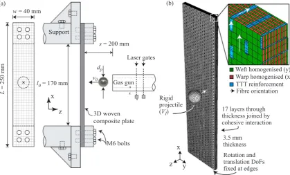
Experiments were conducted in order to determine the damage modes presented during ballistic impact of beam samples, and for ballistic impact numerical modelling validation. Fig. 3(a) presents a sketch of the experimental set-up for ballistic impact upon orthogonal 3D woven composite beam samples. Samples of widthw= 40 mm, and lengthL= 250 mm were cut from fully cured composite panels. Beam samples were chosen for validation to allow for the recording of the transient back-face deflection of samples through-out the test. Four holes for M6 bolts were drilled into the top and bottom of the samples, and the beams werefixed into a steel samplefixture. The steel sample fixture was bolted onto an aluminium alloy frame, housed within a protective polycarbonate shield. Clamped beams had a free length l0= 170 mm. The stand-offbetween the front edge of the sample and the gas gun was s= 200 mm. Stainless steel spherical projectiles of diameter dp= 12.7 mm and mass mp= 8.3 g were accelerated via a
pressurised gas gun. The gas gun utilised pressurised air up to a pres-sure of 6.5 bar, or pressurised nitrogen (oxygen free) for prespres-sures up to 45 bar. The pressurised gasfilled a 3-litre diving cylinder. Pressure was released via a fast-acting solenoid valve. The gas gun had a stainless-steel barrel of length 3.5 m, bore diameter 13 mm and thickness 1.5 mm. A series of holes were drilled into the muzzle end of the barrel in order to allow for gas release. Two laser gates were set up at the muzzle end of the barrel in order to measure the exit velocity of pro-jectile. The velocity measured by the laser gates was confirmed with high speed photography. Projectiles in the experiments were ac-celerated to a velocity range60 ms−1⩽v ⩽190 ms−
[image:4.595.101.494.54.208.2]0 1giving a projectile kinetic energy range of15 J⩽Jk⩽149 J. This velocity range corre-sponds to characteristic impact events from debris striking the under-side of an aircraft during take-offand landing[7]. High-speed photo-graphy was used to record the transient deformation and damage mechanisms of beams during impact. The back-face is defined at the surface of the sample distal to the projectile impact. The high-speed camera model Phantom Mercury HS v12.1 with a global electronic shutter, a frame rate of approximately 57,000 fps and an exposure time of 10μs was used. At a resolution of 304 × 400, this gave an Fig. 2.Quasi-static stress strain relationships for 3D woven carbon composite material for (a) tension and (b) compression.
L
= 250 mm
w
= 40 mm
M6 bolts
l
0= 170 mm
d
pv
0Gas gun
3D woven
composite plate
Support
s
= 200 mm
Laser gates
Weft homogenised (y)
Warp homogenised (x)
TTT reinforcement
Rotation and
translation DoFs
fixed at edges
3.5 mm
thickness
17 layers through
thickness joined by
cohesive interaction
(a)
(b)
z
x
X Y Z
Rigid
projectile
(
V
I)
Fibre orientation
y
z
x
[image:4.595.87.507.473.726.2]approximate pixel size on the front surface of beam samples of 0.35 mm.
3. Finite element simulation
3.1. Thefinite element model
Three-dimensional (3D) finite element (FE) modelling was con-ducted using the explicit solver of ABAQUS (Version 6.12). Each of the 17 layers of the composite material as well as the TTT reinforcement were modelled separately using 4-noded doubly curved reduced in-tegration shell elements (S4R in ABAQUS notation), with 5 inin-tegration points through the thickness. Justification of the shell element choice is primarily owing to the high in-plane length to thickness ratio of each ply, relatively low impact velocities, and a rounded projectile geometry. Further justification of the shell element choice being that at impact velocities in the vicinity of the ballistic limit of CFRP composite beams/ plates, the dominant failure mechanism of the in-plane fibre archi-tecture is expected to be that of tensile fracture[5]. The element size for the FE model was approximately 800μm, by which the converged re-sults can be achieved according to numerical experiment. With this element size, the beam impact samples were discretised into approxi-mately 210,000 shell elements. A typical run time for a full impact event was around 8 h. The ABAQUS orientation assignment control was used to assign localfibre orientations for individual layers. The surface-based cohesive contact interaction within ABAQUS was employed to simulate the interaction between layers through the thickness of the beams/plates, by which delamination under dynamic impact can be simulated, as described in theSupplementary Data. The through-the-thickness reinforcement was explicitly modelled, independently to the in-planefibre architecture, with geometric parameters again taken from cross-sectional microscopic images. The translational and rotational nodal degrees of freedom (DoF) of the through-the-thickness re-inforcement were tied to the translational and rotational nodal DoF of the in-plane fibre architecture via the tie constraint option within ABAQUS. The stainless steel projectile was assumed to incur negligible deformation throughout the penetration event, and was modelled as a discrete rigid body (C3D8R in ABAQUS notation). The mass of the projectile was assigned by the inertial assignment function within ABAQUS, at the centre of the projectile. Penalty based contact method with general contact option within ABAQUS was used to simulate the interaction between the projectile and beams/plates.
3.2. Description of the constitutive model employed for FE simulations
The orthogonal 3D woven carbon composite was split into 17 layers through the thickness, corresponding to the 9 weft and 8 warp tow layers. A cohesive contact law was used to model the interface between layers, which simulates the traction-separation behaviour between
them and allows the FE model to simulate delamination at these loca-tions. The effective traction-separation behaviour followed that as presented by Camanho and Davila[2]. The local coordinate system for each layer and TTT-reinforcement is denoted by numbers, with 11 and 22 being longitudinal and transverse to the in-planefibre direction, respectively. Each layer and TTT-reinforcement were treated as an or-thotropic material under plane stress condition, i.e.σ33=σ13=σ23=0. The in-plane stress-strain relation for the materials without damage is given as ⎧ ⎨ ⎩ ⎫ ⎬ ⎭ = ⎡ ⎣ ⎢ ⎢ − − ⎤ ⎦ ⎥ ⎥ ⎧ ⎨ ⎩ ⎫ ⎬ ⎭ ε ε γ
E ν E
ν E E
G σ σ σ
1/ / 0
/ 1/ 0
0 0 1/
11 22 12
11 12 11
21 22 22
12 11 22 12
(1) whereσ i jij( , =1,2) are in-plane stress components;ε11andε22 are the direct strains in the 11 and 22 directions, respectively;γ12 is the en-gineering shear strain;E11,E22,G12, ν12 andν21are Young’s modulus along the two directions, in-plane shear modulus and the two Poisson’s ratios withν21=(E22/E11)ν12, respectively.
For the warp layer, the weft layer, and the TTT-reinforcement, the anisotropic damage model developed by Matzenmiller et al.[8]as well as the damage initiation model forfibre reinforced composites devel-oped by Hashin (1980) were employed in the simulation, which ac-counts for the four damage modes, i.e.fibre rupture under tension,fibre buckling and kinking under compression, matrix cracking under transverse tension and shear, and matrix crushing under transverse compression or shearing. Similar to the concept of yield surface in plasticity theory, the damage locus could be defined in the space of stress according to the Hashin damage initiation criteria. For a stress state within the damage locus, the material is in undamaged state and the stress-strain relation is described by Eq.(1). Damage initiates when the critical stress state in the damage locus is attained or exceeded. Four scalar damage variables, corresponding to the four damage modes, are introduced to represent the effects of the damage modes. Post initiation of damage, the response of the material is governed by
⎧ ⎨ ⎩ ⎫ ⎬ ⎭ = ⎧ ⎨ ⎪ ⎩ ⎪ − − − − − − − ⎫ ⎬ ⎪ ⎭ ⎪ ⎧ ⎨ ⎩ ⎫ ⎬ ⎭ ε ε γ
E d ν E d
ν E d E d
G d
σ σ σ
1/[ (1 )] /[ (1 )] 0
/[ (1 )] 1/[ (1 )] 0
0 0 1/[ (1 )]
, f f m m s 11 22 12
11 21 11
12 22 22
12 11 22 12 (2) where =⎧ ⎨ ⎩ ⩾ = ⎧ ⎨ ⎩ ⩾
d d σ
d d d σ d if 0 otherwise and if 0 otherwise. f f t f
c m m
t
mc
11 22
Here,dft,dfc,dmt anddmc are the damage variables forfibre damage under
tension and compression, matrix damage under tension and compres-sion, respectively.dsis the shear damage variable, defined as
≡ − − − − −
[image:5.595.353.515.78.212.2]ds 1 (1 dft)(1 dcf)(1 dmt)(1 dmc). (3) Table 1
Material properties for warp layer and weft layer.
Orientation Warp Weft
Density (kg m−3) 1525 1530
E1(GPa) 122.2 126.4
E2(GPa) 3.5 3.5
G12(GPa) 5.78 4.93
ν12 0.25 0.25
XT(MPa) 1590 1590
XC(MPa) 1280 1040
Y(MPa) 80 80
J lft/
e(MPa) 12.41 12.00
J lfc/e(MPa) 8.04 5.13
Jm/le(MPa) 6.5 6.5
Table 2
Material properties for TTT-reinforcement.
Property Value
Density (kg m−3) 1628
E1(GPa) 146.8
E2(GPa) 3.5
G12(GPa) 14.37
ν12 0.25
XT(MPa) 2020
XC(MPa) 1610
Y(MPa) 80
J lft/
e(MPa) 16.68
J lfc/e(MPa) 10.60
[image:5.595.38.289.80.212.2]It can be treated as a resultant damage variable, combining tension and compression for both longitudinal and transverse directions. In the undamaged state, the damage variables are set to zeros. During the damage initiation and evolution, these damage variables increased
from zeros to a maximum value of unity controlled by the strain in the material. The damaged elements were removed from the mesh when one of the damage variables reaches unity.
[image:6.595.53.393.56.671.2]The damage evolution law follows that proposed by Matzenmiller Fig. 4.Time history of back-face deflection after impact at the selected projectile initial velocities (v =70 ms−
et al.[8]. The damage will only develop when the stress state exceeds the critical stress surface given by
〈 〉
− ⩽
σ d X
(1 ft) T 1,
11 (4) −〈 〉 − ⩽ σ d X
(1 fc) C 1,
11 (5) ⎜ ⎟ ⎜ ⎟ ⎛ ⎝ 〈 〉 − ⎞ ⎠ + ⎛ ⎝ − ⎞ ⎠ ⩽ σ d Y σ d Y (1 ) 2
(1 ) 1,
mt s
11 2 12 2 (6) or ⎜ ⎟ ⎜ ⎟ ⎛ ⎝ 〈− 〉 − ⎞ ⎠ + ⎛ ⎝ − ⎞ ⎠ ⩽ σ d Y σ d Y (1 ) 2
(1 ) 1,
mc s
22 2
12 2
(7) where〈〉represents the Macaulay bracket of value zero when its aug-ment is negative. XT and XC denote the tensile and compressive
strength at damage initiation during loading along thefibre direction.Y denotes the tensile and compressive strength along the transverse di-rection.
The four independent damage variables,dft,dcf,dmt, anddmc, increase
if the stress state lies beyond the critical space defined in Eqs.(4) to (7). The damage variables are assumed to evolve in a way that the stress
decreases linearly with increasing strain once damage initiates. The following relations are used to update the damage variables
⎜ ⎟ = 〈 〉− 〈 〉⎛ ⎝ − ⎞ ⎠ ⩽ d
ε X E
ε X E
( / ) / 1, f t J l X T J l X T 2 11 11 11 2 11 f t e T f t
e T (8)
= 〈 〉− 〈 〉⎛ ⎝ − ⎞ ⎠ ⩽ d
ε X E
ε X E
( / ) / 1, f c J l X c J l X c 2 11 11 11 2 11 f c e c f c
e c (9)
= 〈 〉 + − 〈 〉 + − ⩽
(
)
dε ε Y E
ε ε Y E
( / ) / 1, mt J l Y J l Y 2
22 2 122 22
22 2 122 2 22 m e m e (10) = 〈− 〉 + − 〈− 〉 + − ⩽
(
)
dε ε Y E
ε ε Y E
( / ) / 1, mc J l Y J l Y 2
22 2 122 22
22 2 122 2 22 m e m e (11)
whereleis a characteristic length scale which is the same as the length
across afinite element;Jft,JfcandJmare the tensilefibre fracture
[image:7.595.67.525.56.468.2]en-ergy, compressivefibre fracture energy and the matrix fracture energy, respectively. The material data employed in the numerical simulation Fig. 5.Comparison between the experimentally observed and the numerically predicted damage mechanisms for a low velocity projectile impact event (v0=76 ms−1). (a) front-face damage distribution with contour showing predicted tensilefibre damagedft, and (b) back-face damage distribution with contour showing predicted matrix tensile damaged
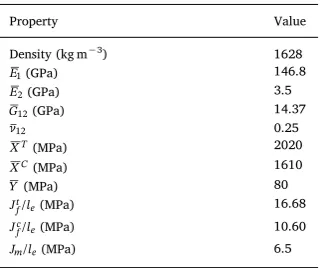
are shown inTables 1and2 [13,14].
The strain-rate dependent response of the 3D woven carbonfibre reinforced composite needs to be considered in order to get satisfactory numerical predications[13]. A viscosity coefficientη, following Duvant and Lions [3], is introduced to further update each of the four pre-viously-defined damage variablesdft,d,
f c d
mt anddmc. The viscous damage
variables are defined as
= −
d
η d d
̇ 1( ),
i v
t i iv
(12) whereηtrepresents the relaxation time of the system, withdi is the
previously defined inviscid damage variable, withidenoting one of the four damage modes (I through IV fordft,dcf,dmt anddmc, respectively).
The termdiv is used to compute the damaged stiffness matrix and is
updated by =
+ + +
+ +
d t
η td
η η td
| Δ
Δ | Δ | .
ivt0 Δt i t0 Δt ivt0
(13) This effectively slows down the rate of damage evolution, with an increasing rate of deformation leading to increasing fracture energies. A numerical calibration study led to the valueη=5 μs. It was assumed to be identical for tension and compression for both longitudinal and transverse damage modes in the simulations. In the following sections, numerical simulations will be presented for ballistic impact of compo-site beams and plates made of the 17 layer orthogonal 3D woven composite material.
4. Orthogonal 3D woven carbon composite beams under ballistic impact
Clamped orthogonal 3D woven carbon composite beams under ballistic impact were investigated numerically and experimentally. The experimental protocol has been detailed in Section 2.3. The FE
simulations were conducted for comparison and validation purposes. Fig. 3(b) shows a sketch of the FE meshed geometry employed in the ballistic impact simulations. The response of these 3D woven composite beams exhibited three distinct mechanisms dependent on the velocity of the projectile:
Low velocity(v <110 ms )−
0 1 - The beam deflects and the projectile is rebounded. Damage incurred within the beam ranges from relatively superficial surfacefibre fracture and localised matrix cracking under projectile location to extensive longitudinalfibre fracture and matrix cracking along the centre of the beam.
Medium velocity(110 ⩽ v <148 ms )−
0 1 –Kinetic energy of the pro-jectile is high enough to cause failure of beam samples. The failure mechanism is stretch dominated; the beam deflects significantly further than the thickness of the beam and longitudinalfibre fracture occurs at the centre line of the beam. This fracture position occurs at the location of through-thickness reinforcement, as this is clearly the location of stress concentrations within the material[14]. The through-thickness reinforcement is revealed upon viewing of the fracture surface.
High velocity(v ⩾ 148 ms )−
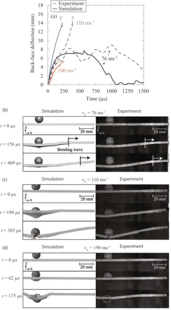
0 1 –Kinetic energy of the projectile is high enough to penetrate through the sample. Projectile penetration occurs before the beam can reach significant out-of-plane deflection. Damage mechanisms are extensivefibre fracture and matrix cracking. Damage of the TTT reinforcement occurred up to 20 mm away from projectile impact site. Specifically, the crowns of the through-thickness reinforcement were damaged. Penetration was also coupled with longitudinalfibre fracture across the centre-line of the sample, similar to that as the medium velocity stretch-dominated damage mode.The time history of the back face deflection after impact is shown in Fig. 4(a) for the beam samples at selected impact velocities, i.e.,
= −
v0 76 ms ,1 v0=110 ms−1andv0=190 ms .−1
[image:8.595.74.520.60.363.2]The selected experimentally recorded and numerically predicted montages after impact are shown inFig. 4(b) through (d). InFig. 4(a), Fig. 6.Optical microscopic images of the cross-sectioned sample after impact by a projectile atv =76 ms−
the time instants at which projectile penetration occur are highlighted with Points labelled ‘P’on the graph and beam fracture with Points labelled‘F’. The agreement between the experimental results and the numerical predictions are reasonably good with regards to failure me-chanism as well as the maximum back-face deflection and time at which it occurs. The accuracy of the prediction decreases as time progresses due to complications arising from imperfect clamped boundary condi-tions within the experimental test[13].
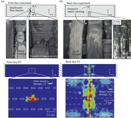
The FE simulations capture the three distinct beam response re-gimes, which will be compared next with the detailed post-test optical microscopic images of the beam samples.Fig. 5(a) and (b) present a comparison between post-test surface optical microscopic images and the numerical prediction at an impact velocity v =76 ms−
0 1 for the
front surface and back surface of the sample, respectively. For the front surface, localised matrix cracking andfibre fracture of surface (weft) tows were both observed and predicted by the numerical model. Small-scale fibre fracture was observed and predicted underneath the pro-jectile strike locations. The back surface demonstrated significant ma-trix cracking across the entire width of the beam. This damage to the matrix was significant enough to cause removal of transverse (weft) tows from the sample via element deletion. As demonstrated by Fig. 5(b), the numerical model predicts significant tensile matrix
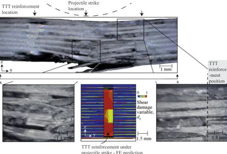
damage incurred within the beam along the centre line of the back-surface of the sample.Fig. 6presents optical microscopic images of the same sample cross-sectioned across the centre line of the beam. The location of the cross-section is that as denoted by x-x inFig. 5(a). It shows the localised, sub-surface damage underneath the projectile lo-cation. The damage includes transverse and inter-laminar matrix cracking and damage to the through-thickness reinforcement under the projectile strike location. Consistent with Turner et al.[14], inter-la-minar matrix crack propagation is arrested by the presence of nearby through-thickness reinforcement. Damage to the TTT-reinforcement is observed and predicted underneath the projectile impact location. The predicted and experimentally observed stretch-dominated failure me-chanism, characterised by in-planefibre fracture across the length of the beam at the centre of the sample, is presented inFig. 7for a medium velocity projectile v =110 ms .−
[image:9.595.63.532.54.477.2]0 1 Brittle fracture reveals through-thickness reinforcement at the fracture surface. The FE predicted con-tour shows the shear damage variables,ds, with fully damaged elements removed from the visualisation. The dominant stretch in-plane tensile fibre fracture mechanism is coupled with localised matrix cracking under the projectile location due to high contact stresses. The matrix cracking is demonstrated on both post-experiment optical microscopic images and the FE prediction. Fibre fracture of transverse surface tows Fig. 7.Comparison between the experimentally observed and predicted damage mechanisms for a medium velocity projectile impact event (v =110 ms−
was predicted and observed approximately 2–4 mm away from the impact strike position.
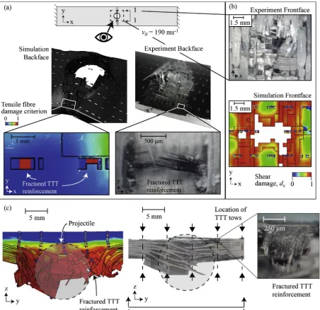
The predicted and experimentally observed penetration damage mechanisms for a high velocity impactv =190 ms−
0 1, characterised by significant localised damage and projectile penetration, is presented in Fig. 8. Longitudinalfibre fractures were both recorded and predicted across the entire width of the 40 mm samples. Tensile fracture of the TTT reinforcement at areas remote from the projectile impact location caused removal of TTT reinforcement crowns. This is shown by a comparison between the post-test optical microscopic images and the FE predicted longitudinal tensilefibre damage of the TTT reinforcement presented inFig. 8.
5. Clamped circular orthogonal 3D woven carbon composite plates under multi-hit ballistic impact
Motivated by the recent investigations on metallic andfibre com-posite plates under multi-hit ballistic impact [6], the FE model was
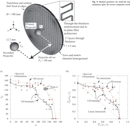
employed for the multi-hit simulations of 3D woven carbon composite circular plates. A sketch of the meshed geometry of the multi-hit FE simulation is presented inFig. 9: the plate sample is hit twice at the same location by two identical steel ball projectiles. The simulation methodology employed by Russell[12]was adopted: whilst thefirst projectile was imparted with a velocityVI at the beginning of the
si-mulation (primary impact), the second projectile was set further away from the plate, and imparted with velocityVII(secondary impact). The
second projectile followed the same trajectory as thefirst. Contact be-tween the two projectiles was removed using the“exclude surface pair”
[image:10.595.72.525.55.493.2]option within ABAQUS, allowing the second projectile to pass through thefirst in order to impact upon the plate. In order to limit the influence from the reflecting stress waves within the plate due to thefirst impact, an off-set of 100 mm between the centre points of the two projectiles is set along the z-direction. Effect of the projectile off-set is presented in Supplementary Data. To verify the multi-hit simulation methodology for carbonfibre composite plates, the simulation on the experimental study reported by Kandan et al.[6]on the multi-hit of a 15-layer 0/90 Fig. 8.(a) and (b) Comparison between the experimentally observed and the numerically predicted damage mechanisms for a high velocity projectile impact event (v =190 ms−
0 1).
carbonfibre reinforced epoxy laminate composite plate is presented in Supplementary Data. The comparison between FE predicted and ex-perimentally recorded ballistic limit surfaces demonstrates that the FE simulation can achieve reasonable accuracy.
5.1. Multi-hit ballistic limit surface
The two projectile velocities,VIandVII, can be used to define a point
in the two-dimensional (2D) space of a binary event that is either projectile rebound or projectile penetration. The predicted multi-hit ballistic limit surfaces for the 3D woven composite plates and the equivalent cross-ply laminate composite without the presence of the TTT reinforcement are shown inFig. 10(a) under the coordinate system
−
V VI II.The comparison of the multi-hit ballistic limit surfaces of the two
materials can be used to examine the effect of the TTT reinforcement. Each individual double-hit impact event is recorded within theV VI− II
space as either a circle for plate survival or a cross for projectile pe-netration. The points located on the multi-hit ballistic limit surfaces were obtained via successive simulations that were conducted of in-creasing projectile velocities until the points in ballistic limit surface were obtained within an accuracy of 2.5 ms−1. The presence of the TTT-reinforcement caused an 8% increase in the predicted ballistic
limit VL for single-hit ballistic impact, i.e. an increase from
VL= 152.5 ms−1 without TTT reinforcement to VL= 165.0 ms−1 in-clusive of TTT reinforcement. Fig. 10(b) presents the ballistic limit surfaces for the two materials, normalised by the predicted ballistic limit of each materialVL. It is useful for demonstrating the difference
between the predicted behaviours of the materials, independent of absolute ballistic limit. Dashed lines are included representing a linear interaction and no interaction between thefirst and second impacts. The effect of TTT reinforcement for improving multi-hit ballistic impact resistance is significant when0.5⩽V VI/ L⩽0.95. For the 3D woven composite, up to a primary impact velocity of approximately
=
VI 0.75VL, the reduction in ballistic limit for the secondary impact is
linearly reduced to 85% of that of un-impacted plates. Primary impacts of velocitiesVI⩾0.75VLdemonstrate a sharp decrease in the predicted
secondary ballistic limit of the plate. This transition point corresponds to the predicted projectile velocity at which causes fracture of the longitudinalfibres throughout the entire thickness of the plate under the projectile location.
5.2. Multi-hit damage mechanisms
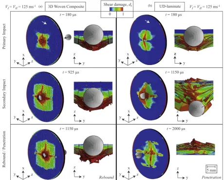
[image:11.595.86.513.53.467.2]Fig. 11(a) and (b) presents a comparison of the damage of composite Fig. 9.Meshed geometry for multi-hit ballistic impact si-mulations upon 3D woven composite circular plates.
plates with and without the presence of the TTT reinforcement for an equi-velocity impact V =V =125 ms−
I II 1, respectively. This event is
marked as Point A in Fig. 10(a). It is at this velocity that the UD-la-minate plate was predicted to have been penetrated, and the 3D woven material predicted to have caused projectile rebound. The primary impact upon the 3D woven material induces concentrated damage underneath the projectile strike location, extending more significantly along the TTT reinforcement orientation. This damage is present throughout the thickness of the plate. The predominant damage mode was predicted to be tensile fracture of in-planefibre architecture. This is combined with compressive damage of the TTT reinforcement crowns directly under the projectile strike position, and tensile damage of the through-thickness component of the TTT reinforcement in the im-mediate surrounding area. The secondary impact then causes a propa-gation of the same damage, following the principal fibre directions, creating a characteristic “cross-shaped” damage distribution. During this stage, the TTT reinforcement is shown to prevent excessive de-formation of the plate, resisting projectile penetration. In spite of in-planefibre fracture occurring throughout the thickness of the plate, the projectile is rebounded.
The equivalent UD-laminate presents a differing damage distribu-tion and penetradistribu-tion mechanism for multi-hit impacts. The primary impact inducesfibre fracture throughout the thickness of the plate. The secondary impact causes the damage to propagate and the character-istic shaped damage mode becomes exaggerated. The
[image:12.595.66.527.56.427.2]cross-shaped damage effectively splits the composite plate into four quad-rants. Without the presence of the TTT reinforcement, bending of these quadrants is unimpeded, allowing for projectile pass-through. After projectile pass-through, the spring-back effect is demonstrated, with the four quadrants returning to their original configuration. This spring-back effect is demonstrative of the bending deformation of the plate. The bending of the plate, and subsequent pass through of the projectile, causes a reduction of damage underneath the projectile for the equivalent UD-laminate case, this is demonstrated in thefinal image in Fig. 11(b). This study focuses on the simulation of rigid-body pro-jectiles. It is anticipated that the relative stiffness of the projectile in comparison to that of the impacted sample would influence the extent of damage progression and the multi-hit ballistic limit surface of the material.
6. Concluding remarks
Ballistic impact experimental tests on clamped rectangular 3D woven carbon composite beam samples were undertaken in order to understand the damage mechanisms within the material and the role of the through-the-thickness (TTT) reinforcement. The experimental study revealed three distinct categories of beam response: (i) low velocity impacts (v <110 ms−
0 1) which demonstrated projectile rebound, with increasing matrix cracking and localised fibre fracture, (ii) medium velocity impact (110 ms−1⩽v <148 ms−
0 1) which exhibited a
stretch-Fig. 11.Isometric and cross-sectional views of predicted damage and deformed configuration of composite plates for an equi-velocity multi-hit eventV =V =125 ms−
I II 1(Point A in
Fig. 10). (a) 3D woven composite, (b) Equivalent UD-laminate material. Contour shows predicted shear damage variable,ds.The white arrow on the surface of the plate is indicative of the
deformation dominated failure mechanism, i.e.“ripping”through the width of the beam at the centre of the sample due to longitudinalfibre fracture, and (iii) higher velocity impacts (v ⩾148 ms−
0 1) which de-monstrated projectile penetration, combined with longitudinal fibre fracture at the centre of the sample. Detailed FE simulations were conducted for interpretation and verification purposes, which were shown to have sufficientfidelity in order to capture the characteristic damage modes of the three response types. The interface between TTT reinforcement and in-plane tows was simplified via the tie constraint option within ABAQUS. The debonding and friction between TTT re-inforcement and in-plane tows were not included. The following roles of the TTT reinforcement have been identified through both experiment and numerical simulations
(1) For both low velocity impact and high velocity impact, the inter-laminar matrix crack propagation can be suppressed by the TTT-reinforcement. The damage of the TTT-reinforcement underneath the projectile suggests that the TTT-reinforcement can increase the material ballistic impact resistance.
(2) For medium velocity impact, the in-planefibre fracture surface was found to be at the locations of TTT-reinforcement. This may suggest that the TTT-reinforcement may create weak points for the stretch-deformation dominated failure mechanism.
FE simulations were conducted to predict the multi-hit ballistic impact limit surfaces for the clamped circular 3D woven composite plates with and without the presence of the TTT reinforcement. The finite element simulations were further validated by a comparison of the multi-hit ballistic limit surface and of the damage modes exhibited during clamped circular plate ballistic impact experiments as presented by Kandan et al.[6]. With the presence of the TTT reinforcement, the 3D woven material was predicted to have a higher concentration of damage under the projectile strike position during ballistic impact loading of clamped circular plates. This is in keeping with the general consensus within the literature for a reduction in the size of damage area due to impact loading with the presence of TTT reinforcement, for example Yen et al.[16]. The enhanced structural integrity of the plate due to the TTT reinforcement was predicted to suppress the develop-ment of damage remote from the projectile strike location, and to re-duce bending deformation within the plate. This led to an 8% increase in the predicted ballistic limit inclusive of TTT reinforcement for a singular impact event. The TTT reinforcement was predicted to improve the multi-hit impact performance of composite plates for multi-hit im-pacts of relatively high primary impact velocity, i.e. the initial impact being 50%–95% of the ballistic limit of the plate.
Acknowledgements
This work was supported by the Engineering and Physical Sciences Research Council, UK [grant numbers EPSRC EP/P505658/1 and EP/ K503101/1]; and the Royal Society through Research Grant Scheme. The authors also acknowledge the use of the High Performance Computing facility at the University of Nottingham forfinite element calculations. 3D woven fabrics were provided by Sigmatex UK.
Appendix A. Supplementary data
Supplementary data associated with this article can be found, in the online version, at http://dx.doi.org/10.1016/j.compstruct.2017.10. 091.
References
[1] Bannister M, Herszberg I, Nicolaidis A, Coman F, Leong KH. The manufacture of glass/epoxy composites with multilayer woven architectures. Compos A Appl Sci Manuf 1998;29(3):293–300.
[2] Camanho PP, Dávila CG. Mixed-mode decohesionfinite elements for the simulation of delamination in composite materials. Tech. Rep. TM-2002-211737, NASA; 2002. [3] Duvant G, Lions JL. Inequalities in mechanics and physics, vol. 219: Springer
Science & Business Media; 2012.
[4] Ghosh R, De S. Z-fiber influence on high-speed penetration of 3D orthogonal woven
fiber composites. Mech Mater 2014;68:147–63.
[5] Hazell PJ, Kister G, Stennett C, Bourque P, Cooper G. Normal and oblique pene-tration of woven CFRP laminates by a high velocity steel sphere. Compos A Appl Sci Manuf 2008;39(5):866–74.
[6] Karthikeyan K, Russell B, Deshpande V, Fleck N. Multi-hit armour characterisation of metal-composite bi-layers. J Mech Mater Struct 2013;7(7):721–34.
[7] Martinez CM, Eylon D, Nicholas T, Thompson SR, Ruschau JJ, Birkbeck J, et al. Effects of ballistic impact damage on fatigue crack initiation in Ti–6Al–4V simulated engine blades. Mater Sci Eng, A 2002;325(1):465–77.
[8] Matzenmiller ALJTR, Lubliner J, Taylor RL. A constitutive model for anisotropic damage infiber-composites. Mech Mater 1995;20(2):125–52.
[9] Mines RAW, McKown S, Birch RS. Impact of aircraft rubber tyre fragments on aluminium alloy plates: I—Experimental. Int J Impact Eng 2007;34(4):627–46. [10] Mouritz AP, Bannister MK, Falzon PJ, Leong KH. Review of applications for
ad-vanced three-dimensionalfibre textile composites. Compos A Appl Sci Manuf 1999;30(12):1445–61.
[11] Peters JO, Ritchie RO. Foreign-object damage and high-cycle fatigue: role of mi-crostructure in Ti–6Al–4V. Int J Fatigue 2001;23:413–21.
[12] Russell BP. Multi-hit ballistic damage characterisation of 304 stainless steel plates
withfinite elements. Mater Des 2014;58:252–64.
[13] Turner P, Liu T, Zeng X. Dynamic response of orthogonal three-dimensional woven carbon composite beams under soft impact. J Appl Mech 2015;82(12):121008. [14] Turner P, Liu T, Zeng X. Collapse of 3D orthogonal woven carbonfibre composites
under in-plane tension/compression and out-of-plane bending. Compos Struct 2016;142:286–97.
[15] Zhou F, Zhang C, Chen X, Zhu C, Hogg PJ. An experimental comparison of different carbon and glass laminates for ballistic protection. In: 18th international conference on composite materials; 2011.