NON INTRUSIVE LIQUID LEVEL DETECTION USING OPTICAL TECHNIQUE
NIK INTAN HAZURA BT NIK ABDUL HALIM
This report is submitted in partial fulfillment of the requirements for the awarded of
Bachelor of Electronic Engineering (Telecommunication Electronics) With Honors.
Faculty of Electronic Engineering and Computer Engineering (FKEKK)
Universiti Teknikal Malaysia Melaka (UTeM)
UNIVERSTI TEKNIKAL MALAYSIA MELAKA
FAKULTI KEJURUTEMAN IJLEKI'RONIK DAN KEJURUTERAAN KOMPUTER
BORANG PENGESAIIAN STATUS 1,APORAN
PROJEK SARJANA MUDA I1
Tajuk Projek NON INTRUSIVE LIQUID LEVEL DETECTION USING
' OPTICAL TECHNIQUE
Sesi Pengajian
Saya NIK INTAN HAZURA BT NIK ABDUL HALIM
(HURUF BESAR)
mengaku membenarkan Laporan Projek Sarjana Muda ini disimpan di Perpustakaan dengan syarat- syarat kegunaan seperti berikut:
1. Laporan adalah hakmilik Universiti Teknikal Malaysia Melaka.
2. Perpustakaan dibenarkan membuat salinan untuk tujuan pengajian sahaja.
3. Perpustakaan dibenarkan membuat salinan laporan ini sebagai bahan pertukaran antara institusi pengajian tinggi.
4. Sila tandakan ( d ) :
(Mengandungi maklumat yang berdarjah keselamatan atau kepentingan Malaysia seperti yang termaktub di dalam AKTA RAIISIA RASMI 1972)
TERHAD* (Mengandungi maklumat terhad yang telah ditentukan oleh
organisasitbadan di mana penyelidikan dijalankan)
Disahkan oleh:
Alamat T e t a ~ . LOT 7181 KG BUKIT DATO'H. TAN KIM SEE
Pensyamh
BATU 7 % TANJUNG MINYAK, F*ulti Universiti Kej Elektronik Teknikal Malaysia Melaka (UTeM), dan Kej Komplta (FKEKK) 75250 MEI,AKA
Kanrng Berkund 1200
Ayer Keroh, 75450 Melaka
"I hereby declare that this report is the result of my own effort except for works that have been cited clearly in the references."
Signature
Author
.
...
Nlr INPIE( NIFA@[O HQLII'YI"I hereby declare that I have read this report and in my opinion this report is sufficient in terms of the scope and quality for the award of the Bachelor of
Electronic Engineering (Telecommunication Electronics) With Honours."
Signature
...
...
Supervisor's Name :
ACKNOWLEDGEMENT
First of all, I would like to thank my supervisor, Mr Tan Kim See. This work
could not have been completed without his support, guidance, patience and humor.
He is an outstanding lecturer, mentor and source of motivation. I will always be
gratefil for his valuable advice and insight. I would like to acknowledge Mr Zaid b. Ahmad who had helped and inspired me to complete this work. Their guidance and
patience in helping me by offering suggestions and ideas to help me in completing
the hardware design are very much appreciated.
I would like to thank my many fellow fiends who had given me the moral
support and understanding in the course of doing my project. Finally, I would like to
have to thank members of my family whose confidence and encouragement in me to
complete my project in time. They are always there to give me their support
vii
Laporan ini mengandungi maklumat dan pengetahuan yang diperolehi dalam
proses menyelesaikan Projek Sarjana Muda (PSM). Penerangan yang terkandung di
dalam laporan ini adalah berdasarkan kajian dari petikan dan pengalaman semasa
menyiapkan projek.
Seperti yang kita sedia maklum, terdapat pelbagai kaedah untuk mengesan
paras cecair terdapat di pasaran. Diantaranya ialah teknologi mengesan paras cecair
tanpa melibat sentuhan antara alat yang digunakan dan cecair. Ini adalah satu sistem
tidak melibatkan penyentuhan secara fuikal dengan jenis cecair yang disukat.
Kaedah yang akan diaplikasikan di dalam projek ini adalah berdasarkan
prinsip optik yang tidak bersentuhan degan cecair yang disukat. Kaedah yang
diketengahkan ini adalah kaedah terbaru yang masih dalarn tempoh kajian. Prinsip
optik dipilih kerana kelajuan dan ketahanannya berbanding dengan kaedah lain.
Konsep yang akan diaplikasikan adalah berdasarkan kecerahan cahaya yang
diterima. Semakin tinggi paras cecair semakin rendah kecerahan cahaya yang
viii
ABSTRACT
This report consists of the knowledge acquired and it encompasses the system
and technologies that are applied in order to complete the final year project. The
explanations are based on literatures, articles and experiences from the actual work
done.
There are many types of liquid level detection already in existence in the
market and it depends on the application by the user. Non-Intrusive liquid level
detection is the system where the detection or measuring of the level of the liquid is
done without any physical contact with the liquid.
The method is based on optical technology whereby object is in direct contact
with the liquid. An optical technique was chosen because of its high speed
performance as compared to other methods. The concept that will be use in the
system is based on the intensity measurement of a laser in term of voltage. The depth
of liquid will be measured based on intensity of laser light. The voltage decreases
CONTENT
CHP TOPIC
PROJECT TITLE DECLARATION DEDICATION ACKOWLEDGEMENT ABSTRACT ABSTRAK CONTENT LIST OF TABLE LIST OF FIGURE
LIST OF ABBREVIATION LIST OF APPPENDM
1.1 Introduction
1.2 Problem Statement 1.3 Objective
1.4 Scope of Work
1.5 Project Methodology
1 .5.1 Finding the project
1.5.2 Project planning
1.5.3 Literature Review
1.5.4 Circuit Design
1.5.5 Building the hardware
1.5.6 Finishing
1.6 Thesis Layout
2 LITERQTURE REVIEW 2.1 Introduction
2.2 Light
2.2.1 Intensity of Light
2.3 Transmitter
2.3.1 Laser
3 NON-INTUSTVE LIQUID LEVEL DETECTION SYSTEM
3.1 Introduction 21
3.2 Design considerations 23
4 RESULT A N D DISCUSSION 4.1 Testsetup
4.2 MEASUREMENTS
4.2.1 Receiver Output
4.2.2 Controller Output 30
5 DISCUSSION & CONCLUSION 5.1 DISCUSSION
5.2 CONCLUSION
6 REFFERENCE
APPENDIX
A. 1 Silicon
PIN
Photodiode SFH 203 PA.2 BiMOS Operational Amplifier CA 3 140
LIST OF TABLE
1.1 Parameters and Operating Conditions
2.1 Characteristic of LED compare with LASER
4.1 Receiver Output 4.2 Setting mode
LIST OF FIGURE
NO
TITLE PAGEBlock Diagram of Liquid Level of an Optical System
Receiver Schematic Diagram
Receiver PCB layout
Display and Control PCB layout
Flow chart for hardware development
Prototype Layout
The wavelength and .frequency of photon
R e h t i o n of white light
Comparison between blue and red spectra due to its wavelength
Relative Intensity for spectrum of light
Laser emission pattern
Illustration of tank with the measurement system
xiii
LIST OF ABBREVIATION
PCB LED IC BCD VR RF RGB LASER
TX
RX
PSM UTeM FKEKK LDPrinted Circuit Board Light Emitting Diode Integrated Circuit Binary Coded Decimal Variable Resistor Resonance Frequency Red Green Blue
Light Amplification Stimulation Emissions Radiation Transmitter
Receiver
Projek Sarjana Muda
Universiti Teknikal Malaysia Melaka
NO TITLE
xiv
LIST OF APPENDIX
A. 1 Silicon PIN Photodiode SFH 203 P
A.2 BiMOS Operational Amplifier CA 3 140
A.3 LM 3914 Dotmar Display
CHAPTER 1
INTRODUCTION
1.1 INTRODUCTION
There are many technologies used to measure liquid level, available in the
market. The examples are RF Admittance, Displacers/Floats, Capacitance,
Ultrasonic, Radar, Nuclear, Differential Pressure, Bubbler and etc. All those types of
level measurement can be accomplished for liquids, granular, slurries and interfaces.
But the truth is that every technology for level measurement works, when used in the
specific circumstances where they have a high probability of success.
Other than that, user demand also plays an important roles to decides the
technology to be used in their industry. They have an options to used point level
system or continuos level system. But most of the user wants a complete, automated
control within a plant site would prefer a continuous level monitoring system.
Furthermore, users need reliable measurement of the contents in their containers, that
they will not cause and overflow or reduce the contents to a critical low point of
Therefore, the existing technology offered both (point and continuos) for
contact and non-contact mesurement depends on the measuring material. In Non-
contact level measurement systems which include the used of laser, non-contact
radar and ultrasonic, they generally show such systems consist of level sensors
located above the material surface that emit signal and process the return
signal(reflections of that signal). Materials that reflect better, produce sttonger
returns and permit measurement over larger distances. In general, solids do not
reflect as well as certain type of liquids, so a given sensor and transmitter will
typically be rated to measure over a shorter distance.
As this project focuses on liquid, its complexity to monitor the reflection is
made more difficult because the material is not static in the tank. Furthemore, it is a
continuous level measurement process. For these reasons, when designing the
system for the project, other relaetd issues have to be considered to overcome the
stated problems. The main advantage of using the non-intrusive method is that the
sensors do not come into direct contact with the liquid. Only a light beam is
transmited into the liquid. The light beam may be affected by airspace conditions
like humidity, heavy vapors and vapor layer stratification due to temperature
fluctuations, along with dealing with heavy dust in the airspace but these can be
accounted and calibrated.
This technology can be used where non-contact to the liquid is desired
especially liquid that is m o s i v e , contaminated or hazardous. It can be used for tank
level measurement on almost any liquid whether in storage or during processing. It is
versatile because any change to the product or process caused by temperature,
pressure, density, conductivity, vapors or dust can be referred to a reference or
threshold quantity. The transmitters and receivers can be concealed in transparent
wells in the tank or container. Once installed, the system operates without harming
1.2 PROBLEM STATEMENT
Liquids such as alkaline or acid need special care in handling, say during the
monitoring of the level in containers or tanks. Due to their corrosiveness, a non-
intrusive method is best used where physical contact to the liquid can be avoided.
Thus the project will be developed to monitor the liquid level using a column for the
detection purposes. A reliable and not too expensive system can be employed to
fulfill the objectives of the proposed project.
Moreover, the idea to develop this project is to contribute more options if not
to overcome any shortcomings of existing systems currently available in the market.
Using this method, the intensity of the light beam will decrease as the level of the
liquid increases. By computing the power at the receiver to the level of the liquid, a
consistent relationship can be developed and translated into liquid level. Once the
maximum level is achieved, a signal can be sent to the valve to stop the inflow pipe.
It is much easier to design a non-contact detection system to monitor at
specific level only. A continuous monitoring system requires a much higher
resolution and is definitely more challenging. It is very important that the liquid in
the tank does not overflow and reduce to a level below critical point. A non-
intrusive system to be able to indicate the level of the liquid at any one point will be
1 3 OBJECTIVE
Most non-contact level sensors cannot accurately measure distances that are
close to the sensor itself. Sensors are typically installed to allow the transmitter to
disregard measurements at these distances. This region is often called the blanking
distance.Therefore, the objective of this project is to find various possible methods in
liquid level measurement system, especially for hazardous material, highly viscous
liquid and chemical.
Certain applications cannot be handled by a common detection method
because some fluids can be very corrosive and hazardous to handle and it's best to
avoid physical contact with them. For example, capacitance systems come into direct
contact with the specimen. One major problem encountered with liquid level
detectors is the coating or the wear and tear on the sensing elements. Even acid and
caustics that don't appear to coat the sensing element are so conductive that the thin
film they leave can cause serious errors in measurement.
This project is to investigate the relevant technology needed and come up
with the most reliable and practical method in noncontacting liquid level detection..
Finally, a system will be designed and developed to be able to handle the task of
1.4 SCOPE OF WORK
In order to implement the project, a few considerations have to be taken in terms of
limitations or conditions to assure that the project will be successfilly develop. There
are a four main areas being identified or considered that needed to be worked out:
a) Types of Liquid
Clear liquid will be used in order to implement the method in mind.
Such liquid like alkaline, acid, water and petrol can be the specimen.
b) Environment Requirement
It is important because it will affect the measurement performance. of
measuring. The performance of laser is limited to cloudy and vapor
space.
c) Source types
There are two types of source that are usually in used which is Light
Emitter Diode (LED) and Laser Diode (LD). At the final of the PSM
project, laser diode will be used.
d) Receiver and Transmitter Sensitivity
Sensitivity of transmitter and receiver is very important as it will
determine the reliable and efficiency of the system.
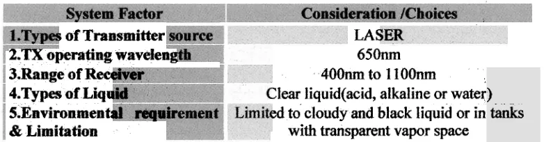
This table below shows the parameters and operating conditions to be considered for
the project
Table 1.1: Parameters and Operating Conditions
r of Transmitter
2. i
x
operating wavelet -3.Range of Recc 4.Types af L i i a 5.EnvironmenC
& Limitatian
LA5
650nm 400nm to 1 1 OOmn
:lear liquidtacid, alkaline or water
xf
to cloudy and black liquid or inwith transparent vapor space
)
[image:19.576.111.502.566.668.2]Other scope of work includes;
1. Literature review to identifl the sensors for optic detection, transmitter and
type of liquid for the specimen of the project.
2. Sourcing for suitable and practical circuits for the project.
3. Develop a prototype system to achieve the objectives of the project.
4. Conduct analysis and testing on the project.
5. Finally to conduct and verifl the functionality of the system.
6. Application of theoretical engineering principles especially on propagation of
optic with the proposed project.
1.5 PROJECT METHODOLOGY Project Outline
Achievement of the project objectives are based on the method and process
employed and should be considered. The various steps below illustrate the process
that have to be done fiom the beginning till the end of the project and being
successfully executed. The subjects below are the outlines of the process:
1.5.1 Finding the project
The first step taken is to find a suitable project that is relevant and up to date
with the technology of today. By referring to several sources such as books,
through the internet and by referring to the supervisor, the various criteria for
the project are used as to where to start.
1.5.2 Project planning
As the title of project was agreed upon and registered, the next step was to
identify the project and discuss with supervisor about the best method to be
used. In order to finish the project according to the time M e given, a Gantt
1.53 Literatare Review
Searching and have a deeper understanding on subjects related to the project
would be the ideal proposition to begin with. Next, fiom the various texts, a
feasible system to support the project was decided. In this project, a non
intrusive system using laser beam would be used as the main principle of
application to achieve the objectives of the project. It is also helpfbl to have a
better understanding about the project based on the past researches. Other
than that, it is necessary to discuss and work with other course-mates who are
doing projects related to the same principles and technology even though
1.5.4 Circuit Design
Circuit designs will be developed based on the information and references
made and under the advices and suggestions of supervisor. Once identified,
the various components and parts have to be purchased. Of course, the correct
specifications and their requirements have to be carefilly identified to avoid
redundant and non compatible parts being supplied. For testing, analysis and
troubleshooting, circuit simulation is best move to determine the hctionality
of the circuits. However, a comprehensive simulation is not possible as there
is no such software available in the laboratory for optical circuits. The nearest
to doing is the testing using Multisim and Pspice. In this process, the circuit
can be tested so that there is no problem with the circuit later on. The circuit
had to be simulated to assure that it can be used and fblfill the requirement of
project.
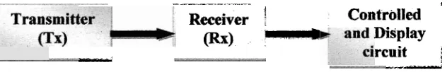
Based on the requirement of the project, three blocks of circuit design
have to be developed. The blocks of the system are shown in the figure below:
- --- -- - -- - ---. -. - - -
-
--
9i
Receiver ; Controlled
(Rx)
-
Displayw rcuit
;
me
-Figure 1.1: Block Diagram of Liquid Level of an Optical System
BLOCK 1
-
Transmit an optical signal (light) constantly.BLOCK 2
-
Receive an optical signal and convert it to electrical signal-
Measure the intensity of light that receive in term of volt (V)BLOCK 3
-
Display the level of liquid reached. [image:23.576.158.474.442.493.2]Block 1
-
TransmitterBlock 1 is a portable laser pointer, which is easily available and can be
used as the transmitter. Therefore the design procedures proceed to the
second block which is an important and the main area of the system.
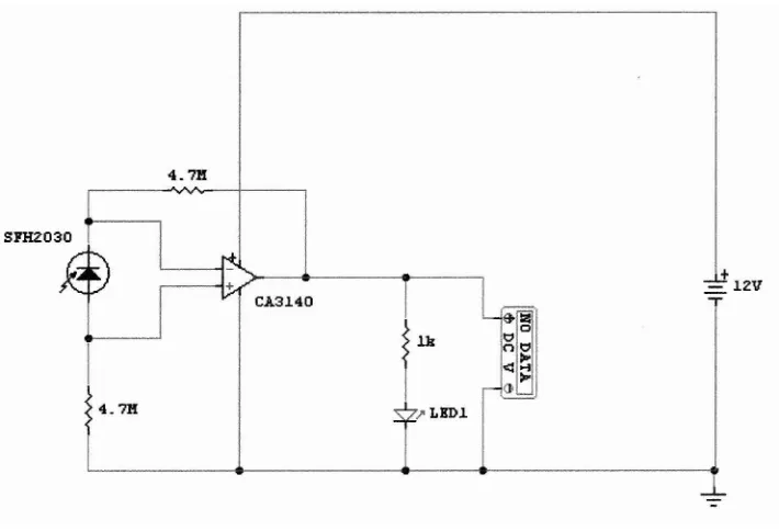
Block 2- Receiver
Block 2 is the detector circuit that is used to detect light source from
the laser pointer. The detector used is the Silicon PIN photodiode which has
very short switching time (5 ns). Therefore, it has high sensitivity to detect the
signal from the transmitter. The feature of SFH 203 P is suitable for this
application from wavelength 400nm to 1100nm. Figure below is a schematic
[image:24.576.150.505.378.620.2]diagram of the receiver.
Figure 1.2: Receiver Schematic Diagram
CA 3140 is used to amplify the voltage that is received fiom the
photodiode. It has a long duration timer and is suitable with photocurrent