0
STUDY AND DEVELOPMENT OF THE DRAG REDUCTION SYSTEM FOR
GO-KART
JULIANOUS KETIHUS
A report in partial fulfilment of the requirements for the degree of Bachelor of
Mechatronics Engineering
Faculty of Electrical Engineering
UNIVERSITI TEKNIKAL MALAYSIA MELAKA
i
“I hereby declare that I have read through this report entitle “Study and Development of The Drag Reduction System for Go-kart” and found that it has comply the partial fulfilment for awarding the degree of Bachelor of Mechatronics Engineering”
Signature : ...
Supervisor‟s Name : MOHD. ZAMZURI BIN AB. RASHID
ii
STUDY AND DEVELOPMENT OF THE DRAG REDUCTION SYSTEM FOR
GO-KART
JULIANOUS KETIHUS
A report in partial fulfilment of the requirements for the degree of Bachelor of
Mechatronics Engineering
Faculty of Electrical Engineering
UNIVERSITI TEKNIKAL MALAYSIA MELAKA
iii
I declare that this report entitle “Study and development of Drag Reduction System for Go-kart” is the result of my own research except as cited in the references. The report has not been accepted for any degree and is not concurrently submitted in candidature of any other degree.
Signature : ……….
Name : JULIANOUS KETIHUS
iv
v
ACKNOWLEDGEMENT
First of all, I would like to thanks to Almighty God, who has blessed and guided me for completion of this report as a partial fulfilment for awarding the degree of Bachelor of Mechatronics Engineering at Universiti Teknikal Malaysia Melaka. A special gratitude and sincerely thanks to my project supervisor, Encik Mohd Zamzuri bin Abdul Rashid, for encouragements, guidance critics and correction for this report from the beginning until the end of this report writing.
In this special moment, I would like to express my deepest thanks to my beloved parents, Ketihus bin John and Iren binti Angkarul for their love encouragement and supports both financially and mentally that made me to finishing this report as well as my study.
vi
ABSTRACT
vii
ABSTRAK
viii
TABLE OF CONTENTS
ACKNOWLEDGEMENT ... V
ABSTRACT ... VI
ABSTRAK ... VII
TABLE OF CONTENTS ... VIII
LIST OF TABLES ... X
LIST OF FIGURES ... XI
LIST OF ABBREVIATIONS ... XV
LIST OF APPENDICES ... XVI
CHAPTER 1 ... 1
INTRODUCTION ... 1
1.1 Motivation ... 1
1.2 Problem Statement ... 5
1.3 Objectives ... 5
1.4 Scopes ... 6
1.5 Report Organization ... 7
CHAPTER 2 ... 8
LITERATURE REVIEW ... 8
2.1 Introduction ... 8
2.2 Analysis of information ... 9
2.3 Synthesis of information ... 12
2.4 Evaluation of infomation ... 15
CHAPTER 3 ... 16
METHODOLOGY ... 16
3.1 Introduction ... 16
3.2 Project Gantt Chart ... 18
ix
3.4 Fabrication Methodology Flow Chart ... 24
3.5 System Block Diagram ... 26
3.6 Process Flow Chart ... 28
3.7 Components selection ... 29
3.8 Front and Rear Wings Design ... 29
3.9 Wings Fabrication ... 30
3.10 Validity of Data ... 33
3.11 Reliability of Data ... 39
3.12 Summary ... 39
CHAPTER 4 ... 40
RESULTS AND DISCUSSION ... 40
4.1 Introduction ... 40
4.2 Solidworks Simulation ... 41
4.2.1 Front wing Simulation ... 41
4.2.2 Rear Wing Simulation ... 47
4.2.3 Full Scale Go-kart Simulation ... 57
4.3 Static Test (Real World Test) ... 67
4.4 Analysis ... 73
4.5 Discussion ... 87
CHAPTER 5 ... 89
CONCLUSION AND RECOMMENDATIONS ... 89
5.1 Introduction ... 89
5.2 Conclusion ... 89
5.3 Recommendation ... 90
REFERENCES ... 91
APPENDICES ... 93
x
LIST OF TABLES
TABLE TITLE PAGE
2.1 Front and Rear Wing Comparison 13
2.2 Drag Force and Downforce comparison 14
3.1 Project Gantt Chart 18
3.2 Input Data Table 33
3.3 Rear Wing Size Parameter 34
3.4 Front Wing Size Parameter 34
3.5 Full Scale Size Parameter 34
4.1 Front wing Goal Plot Table Result 42
4.2 Rear Wing (DRS OFF) Goal Plot Table Result 47
4.3 Rear Wing (DRS ON) Goal Plot Table Result 52
4.4 Full Scale (DRS OFF) Goal Plot Table Result 57
4.5 Full Scale (DRS ON) Goal Plot Table Result 60
4.6 Go-kart’s Front Wing Pressure Simulation Result comparison 73
4.7 DRS OFF and DRS ON of Rear Wing comparison 75
4.8 DRS ON and DRS OFF of Full Scale Go-kart comparison 80
4.9 Flow trajectories of Rear Wing comparison (Isometric View) 85
4.10 Flow trajectories of Rear Wing comparison (Side View) 85
xi
LIST OF FIGURES
FIGURE TITLE PAGE
1.1 Drag reduction system 3
1.2 DRS Deactivated 3
1.3 DRS Activated 3
1.4 Front Wing 4
2.1 Forces acting on a car 8
2.2 Three components of aerodynamic force 11
3.1 (a) Project flow chart (part 1) 19
3.1 (b) Project flow chart (part 2) 21
3.1 (c) Project flow chart (part 3) 22
3.2 Experimental and setup flow chart 24
3.3 DRS Block Diagram 26
3.4 Open-Loop DRS Block Diagram 27
3.5 Process flow chart 28
3.6 Front Wing Final Design 29
3.7 Rear Wing Final Design 30
3.8 Front Wing Fabricated using PVC Foam 30
3.9 Linkage of Servo Motor 31
3.10 DRS Control Unit 32
3.11 Canopy Tent 36
3.12 Go-kart under Static Test 36
3.13 Front Wing Dimension in millimetre (mm) 37
3.14 Rear Wing Dimension in millimetre (mm) 37
4.1 Element in Aerodynamics 40
4.2 Front Wing 42
4.3 Isometric View for Pressure Flow Trajectories 42
xii
FIGURE TITLE PAGE
4.5 Side View for Pressure Flow Trajectories 43
4.6 Top View for Pressure Flow Trajectories 44
4.7 Isometric View for Surface Plot Pressure 44
4.8 Front View for Surface Plot Pressure 45
4.9 Side View for Surface Plot Pressure 45
4.10 Top View for Surface Plot Pressure 46
4.11 Rear Wing 47
4.12 Isometric View for Pressure Flow Trajectories (DRS OFF) 48
4.13 Front View for Pressure Flow Trajectories (DRS OFF) 48
4.14 Top View for Pressure Flow Trajectories (DRS OFF) 49
4.15 Top View for Pressure Flow Trajectories (DRS OFF) 49
4.16 Isometric View for Pressure Surface Plot (DRS OFF) 50
4.17 Front View for Pressure Surface Plot (DRS OFF) 50
4.18 Side View for Pressure Surface Plot (DRS OFF) 51
4.19 Top View for Pressure Surface Plot (DRS OFF) 51
4.20 Isometric View for Pressure Flow Trajectories (DRS ON) 52
4.21 Front View for Pressure Flow Trajectories (DRS ON) 53
4.22 Top View for Pressure Flow Trajectories (DRS ON) 53
4.23 Top View for Pressure Flow Trajectories (DRS ON) 54
4.24 Isometric View for Pressure Surface Plot (DRS ON) 54
4.25 Front View for Pressure Surface Plot (DRS ON) 55
4.26 Side View for Pressure Surface Plot (DRS ON) 55
4.27 Top View for Pressure Surface Plot (DRS ON) 56
4.28 Full Scale Go-kart Solidworks Drawing 57
4.29 Isometric View for Pressure Flow Trajectories (DRS OFF) 58
4.30 Front View for Pressure Flow Trajectories (DRS OFF) 58
4.31 Side View for Pressure Flow Trajectories (DRS OFF) 59
4.32 Isometric View for Pressure Surface Plot (DRS OFF) 60
4.33 Front View for Pressure Surface Plot (DRS OFF) 60
4.34 Side View for Pressure Surface Plot (DRS OFF) 61
4.35 Top View for Pressure Surface Plot (DRS OFF) 61
xiii
FIGURE TITLE PAGE
4.37 Front View for Pressure Flow Trajectories (DRS ON) 63
4.38 Side View for Pressure Flow Trajectories (DRS ON) 63
4.39 Top View for Pressure Flow Trajectories (DRS ON) 64
4.40 Isometric View for Pressure Surface Plot (DRS ON) 65
4.41 Front View for Pressure Surface Plot (DRS ON) 65
4.42 Side View for Pressure Surface Plot (DRS ON) 66
4.43 Top View for Pressure Surface Plot (DRS ON) 66
4.44 Go-kart 67
4.45 Go-kart’s Front Wing 67
4.46 Go-kart’s Front Wing Testing (a) 68
4.47 Go-kart’s Front Wing Testing (b) 68
4.48 Go-kart’s Front Wing Testing (c) 69
4.49 Go-kart’s Front Wing Testing (d) 69
4.50 Go-kart’s Rear Wing 70
4.51 Go-kart’s Front Wing (DRS OFF) Testing (a) 70
4.52 Go-kart’s Front Wing (DRS OFF) Testing (b) 71
4.53 Go-kart’s Front Wing (DRS OFF) Testing (c) 71
4.54 Go-kart’s Front Wing (DRS ON) Testing (a) 72
4.55 Go-kart’s Front Wing (DRS ON) Testing (b) 72
4.56 Go-kart’s Front Wing (DRS ON) Testing (c) 73
4.57 Graph of Drag Force of a Rear Wing during DRS ON and DRS OFF
Comparison 76
4.58 Graph of Downforce of a Rear Wing during DRS ON and DRS OFF
Comparison 77
4.59 Graph of Drag Coefficient of a Rear Wing during DRS ON and DRS OFF
Comparison 78
4.60 Graph of Downforce Coefficient of a Rear Wing during DRS ON and DRS
OFF Comparison 79
4.61 Graph of Drag Force of a Rear Wing during DRS ON and DRS OFF
Comparison 81
4.62 Graph of Downforce of a Rear Wing during DRS ON and DRS OFF
xiv
FIGURE TITLE PAGE
4.63 Graph of Drag Coefficient of a Rear Wing during DRS ON and DRS OFF
Comparison 63
4.64 Graph of Drag Force of a Rear Wing during DRS ON and DRS OFF
Comparison 64
A1 Front wing solidworks drawing dimension 94
A2 Front wing solidworks drawing dimension 95
A3 Rear wing solidworks drawing dimension 96
A4 Rear wing solidworks drawing dimension 97
C1 Circuit Diagram 102
xv
LIST OF ABBREVIATIONS
DRS - Drag Reduction System
xvi
LIST OF APPENDICES
APPENDIX TITLE PAGE
A Solidworks Drawing 93
B Turnitin Report 98
C Circuit Design 100
1
CHAPTER 1
INTRODUCTION
1.1 Motivation
Aerodynamic plays important role in every race car to achieve the top speed instead of depend only on the engine horsepower. The innovative of aerodynamic design affects the speed of a race car, means the more aerodynamic of the car, the faster the speed of the vehicle and vice versa. The most important in aerodynamic research and development is to produce downforce, minimum aerodynamic drag and good directional stability [1]. The aim of every aerodynamic research is to channel the airflows perfectly through the car body, in order to generate as much downforce as possible; therefore the downforce will thrust the car down to onto the road and decreasing the clearance between the lower body parts to the road. This permits shorter braking distance and higher cornering speed [2].
2
3
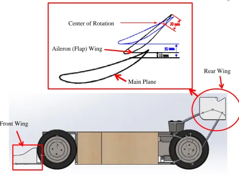
Figure 1.1: Drag Reduction System
[image:21.595.191.425.431.562.2] [image:21.595.191.424.596.738.2]
Figure 1.2: DRS deactivated [3]
Figure 1.3: DRS activated [3] Front Wing
Rear Wing Center of Rotation
4
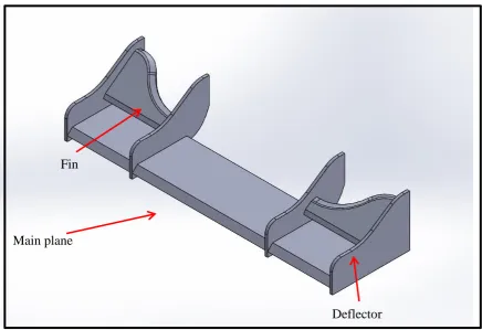
[image:22.595.92.529.273.572.2]This project is about a drag reduction system (DRS) for go-kart. The rear wing DRS capable to improve the straight line speed of race car. The front wing aerodynamic design allows increasing the downforce of the race car. This system capable to reduce the aerodynamic drag force to generate more stream line speed and improve car’s handling stability. This DRS has two set of aerofoil (main plane and flap wing) connected to each other by the wing endplate and an actuator. The flap (aileron) wing can rotate only between 10mm to 50mm from the main plane. The flap rotate by using actuator that control by the driver. The front wing, which is responsible to produce downforce consist of deflector, fin, and main plane as shown in Figure 1.4.
Figure 1.4: Front Wing
. The front and rear wing are designed by using Solidworks software. The
aerodynamic flow motions of this wing are simulated by using Solidworks Flow Simulation software to yield aerodynamics forces and coefficients. These wings are built using PVC foam. The actuator to actuate the flap wing is controlled by using on/off control circuit.
Deflector Fin
5
1.2 Problem Statement
The purpose of DRS is to improve speed of a race car during overtaking situation. However, there are two enemies of speed in race car aerodynamics which is excess in drag force and lack of downforce. These two forces are the main constrain in every race car in order to achieve top speed. The drag is the resultant force in the direction of the upstream velocity [5], it opposes the forward motion of the vehicle. Excess in drag (wind resistance) reducing the effectiveness of the time and required more engine horsepower to achieve top speed. Lack of downforce can reduce the traction and road grip [3]. This reduction on tire traction can be very dangerous during the race car is braking or cornering. Oversteers will occurs if there is little grip at the rear of the car compare to the front. The main problem in aerodynamic design of a race car is how to provide sufficient downforce as well as minimum aerodynamic drag. Therefore, the current concern in this project is about on how to balance the downforce and aerodynamic drag. In order to balance these forces, a fundamental engineering knowledge of aerodynamics is essential as well as the downforce and drag force theories.
1.3 Objectives
The objectives of this project are listed as follows:
1. To study aerodynamic front and rear wings for go-kart in term drag force and
downforce.
2. To develop the go-kart Drag Reduction System (DRS) and test its performance
in term of aerodynamics element (drag force, downforce, drag coefficient, downforce coefficient) using simulation software and static test (real world test).
6
1.4 Scopes
The scopes of the project are summarized as follows:
1. This study concentrates on front and rear wings only and does not include study
into other aerodynamic devices such as diffusers, venturies and body part.
2. Testing of the wings is limited to the analysis using Solidworks Flow simulation
software and static test only.
3. The development of adjustable/actuated wing (DRS) only for the rear wing.
4. This study does not include material study or constructability analysis.
Manufacturing consideration will be ignored in this study.