Rochester Institute of Technology
RIT Scholar Works
Theses
5-2019
Global Congestion and Fault Aware Wireless
Interconnection Framework for Multicore Systems
Sajeed Mohammad Shahriat [email protected]
Follow this and additional works at:https://scholarworks.rit.edu/theses
This Thesis is brought to you for free and open access by RIT Scholar Works. It has been accepted for inclusion in Theses by an authorized administrator of RIT Scholar Works. For more information, please [email protected].
Recommended Citation
Global Congestion and Fault Aware Wireless
Interconnection Framework for Multicore Systems
Global Congestion and Fault Aware Wireless
Interconnection Framework for Multicore Systems
Sajeed Mohammad Shahriat
A Thesis Submitted in Partial Fulfillment of the Requirements for the Degree of Master of Science
In
Electrical Engineering
Supervised by Dr. Amlan Ganguly
Department of Computer Engineering Kate Gleason College of Engineering
Rochester Institute of Technology Rochester, NY
May 2019
i
Global Congestion and Fault Aware Wireless
Interconnection Framework for Multicore Systems
Sajeed Mohammad Shahriat May 2019
Committee Approval:
---
Dr. Amlan Ganguly, Advisor Date
Associate Professor – R.I.T Dept. Of Computer Engineering
---
Dr. Andres Kwasinski Date
Professor – R.I.T Dept. Of Computer Engineering
---
Dr. Panos P. Markopoulos Date
Assistant Professor – R.I.T Dept. Of Electrical and Microelectronic Engineering
---
Dr. Sohail Dianat Date
ii
ACKNOWLEDGEMENTS
This thesis would not have been possible without the motivational and intellectual support of many
people. First and foremost I would like to thank my advisor Dr. Amlan Ganguly, who has mentored
and guided me almost throughout my time at RIT. He has taught me invaluable research skills and
has helped shape the work that is presented in this thesis book. My sincere thanks also goes to Dr.
Andres Kwasinski and Dr. Panos P. Markopoulos to agreeing to be my thesis external committee
members and provide there invaluable ideas and suggestions wherever needed. I would also like
to thank all my mentors and colleagues I made during my internship at AMD, especially Ray
Talacka, Steve Anderson and my manager David Meyerhofer. Lastly, but not the least I would like
to thank my family and friends who has been a constant source of emotional support during my
iii
ABSTRACT
Multicore processors are getting more common in the implementation of all type of computing
demands, starting from personal computers to the large server farms for high computational
demanding applications. The network-on-chip provides a better alternative to the traditional bus
based communication infrastructure for this multicore system. Conventional wire-based NoC
interconnect faces constraints due to their long multi-hop latencies and high power consumptions.
Furthermore high traffic generating applications sometimes creates congestions in such system
further degrading the systems performance.
In this thesis work, a novel two-state congestion aware wireless interconnection framework for
network chip is presented. This WiNoC system was designed to able to dynamically redirect traffic
to avoid congestion based on network condition information shared among all the core tiles in the
system. Hence a novel routing scheme and a two-state MAC protocol is proposed based on a
proposed two layer hybrid mesh-based NoC architecture. The underlying mesh network is
connected via wired-based interconnect and on top of that a shared wireless interconnect
framework is added for single-hop communication. The routing scheme is non-deterministic in
nature and utilizes the principles from existing dynamic routing algorithms. The MAC protocol
for the wireless interface works in two modes. The first is data mode where a token-based protocol
is utilized to transfer core data. And the second mode is the control mode where a broadcast-based
communication protocol is used to share the network congestion information. The work details the
switching methodology between these two modes and also explain, how the routing scheme
utilizes the congestion information (gathered during the control mode) to route data packets during
normal operation mode. The proposed work was modeled in a cycle accurate network simulator
iv
Abbreviations
1. NoC: Network On Chip
2. IC: integrated circuits
3. SoC: System-on- chip
4. MPSoC: Multi-processor System-on-chip
5. WDM: Wavelength Division Multiplexing
6. EM: Electromagnetic
7. TSV: Through Silicon Via
8. CMOS: Complementary MOSFET
9. MOSFET: Metal Oxide Semiconductor Field Effect Transistor
10.UWB: Ultrawideband
11.CNT: Carbon nanotube
12.WI: Wireless Interface
13.CDMA: Code Division Multiple Access
14.TDMA: Time Division Multiple Access
15.WiNoC: Wireless Network-on-Chip
16.BFT: Butterfly Fat Tree
17.MAC: Media Access Control
18.VC: Virtual Channel
19.OOK: On-Off Keying
v
TABLE OF CONTENTS
Signature Sheet. . . i
Acknowledgements. . . ii
Abstract. . . iii
Abbreviations. . . iv
Table of Contents. . . v
List of Tables. . . .vii
List of Figures. . . . vii
Chapter 1: INTRODUCTION. . . 1
1.1: Emerging Interconnect Technologies. . . 3
1.2: Designing wireless interconnect- Challenges and Benefits. . . 5
1.3: Significance of Routing schemes, communication protocols and selection strategy in NoCs. . . 9
1.4: Fault Tolerance in NoCs. . . 10
1.5: Contributions of this thesis work. . . . 10
1.6: Thesis organization. . . 12
Chapter 2: RELATED WORKS. . . . 14
Chapter 3: SYSTEM ARCHITECTURE. . . 19
3.1: Proposed WiNoC topology and design. . . 19
3.2: Wireless interface physical layer. . . . .22
3.3: Operation modes. . . .26
3.4: Routing scheme and controller design. . . .30
vi
3.6: Simulation setup and methodology. . . 39
3.7: Performance evaluation under Uniform Random Traffic. . . .42
3.8: Performance evaluation under Transpose Traffic. . . .45
3.9: Performance evaluation under Hotspot Traffic. . . . 48
3.10: Energy consumption. . . . 51
Chapter 4: FAULT TOLERANCE STUDY. . . .53
Chapter 5: CONCLUSION AND FUTURE WORK. . . 57
vii
LIST OF TABLES
Table I: General and wireless configurations for simulation. . . . 40
LIST OF FIGURES
Figure 1: Proposed 8x8 WiNoC Framework. . . . . . . . . . . . . 19
Figure 2: Proposed subnet architecture. . . . . . . . . . . . . . . . 21
Figure 3: proposed zig-zag antenna placement on the die. . . . . . . . . . . . . . . . . . . . . . 22
Figure 4: (a) Transmitter (b) receiver block diagram. . . . . . . . . . . . . . . . . . . . . . . . . . 23
Figure 5: (a) Control packet (b) State diagram. . . . . . . . . . . . . . . . . . . . . . . . . . . . . . 26
Figure 6: The routing scheme flowchart. . . . . . . . . . . . . . . . . . . . . . . . . . . . . . . . . 30
Figure 7: Block diagram for the router architecture. . . . . . . . . . . . . . . . . . . . . . . . . . . 33
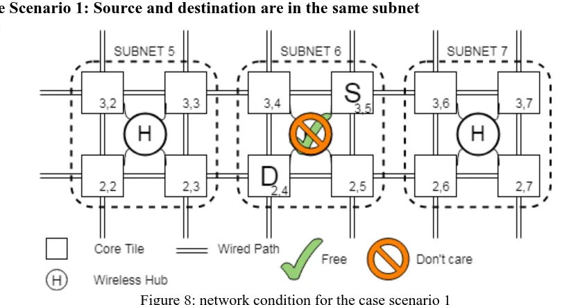
Figure 8: Network condition for the case scenario 1. . . . . . . . . . . . . . . . . . . . . . . . . . .35
Figure 9: Network condition for the case scenario 2 (a) adjacent (b) diagonal. . . . . . . . . . . 36
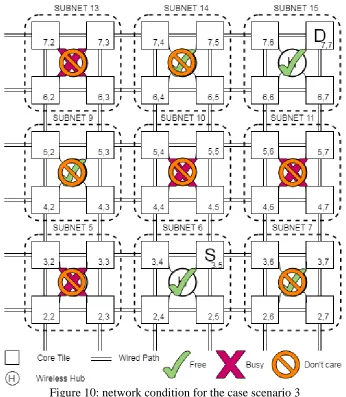
Figure 10: Network condition for the case scenario 3. . . . . . . . . . . . . . . . . . . . . . . . . . 37
Figure 11: Network condition for the case scenario 4. . . . . . . . . . . . . . . . . . . . . . . . . . 38
Figure 12: Global average delay VS PIR for network sizes (a) 6x6 (b) 8x8 (c) 10x10 under Uniform
Random Traffic . . . . . . . . . . . . . . . . . . . . . . . . . . . . . . . . . . . . . . . . . . . .42-43
Figure 13: Throughput VS PIR for network sizes (a) 6x6 (b) 8x8 (c) 10x10 under Uniform Random
Traffic. . . . . . . . . . . . . . . . . . . . . . . . . . . . . . . . . . . . . . . . . . . . . . . . .43-44
Figure 14: Global average delay VS PIR for network sizes (a) 6x6 (b) 8x8 (c) 10x10 under
viii
Figure 15: Throughput VS PIR for network sizes (a) 6x6 (b) 8x8 (c) 10x10 under Transpose
Traffic. . . . . . . . . . . . . . . . . . . . . . . . . . . . . . . . . . . . . . . . . . . . . . . . . . . . 46-47
Figure 16: Global average delay VS PIR for network sizes (a) 6x6 (b) 8x8 (c) 10x10 under Hotspot
Traffic . . . . . . . . . . . . . . . . . . . . . . . . . . . . . . . . . . . . . . . . . . . . . . . . . 48-49
Figure 17: Throughput VS PIR for network sizes (a) 6x6 (b) 8x8 (c) 10x10 under Hotspot Traffic.
. . . . . . . . . . . . . . . . . . . . . . . . . . . . . . . . . . . . . . . . . . . . . . . . . . . . .49 -50
Figure 18: Total energy consumption for three simulated systems. . . . . . . . . . . . . . . . . . 51
Figure 19: Fault modeling and the Hotspot tiles. . . . . . . . . . . . . . . . . . . . . . . . . . . . . 53
Figure 20: 8x8 (a) Global Average Delay VS PIR (b) Throughput VS PIR. . . . . . . . . . . . 54
1
Chapter 1: INTRODUCTION
Transistor scaling has come a long way since the Moore’s law was presented. Current industry
trends show that, transistors will no longer will be able to be scaled (effectively) after the year
2021 [1]. With regards to that, the single uniprocessor systems also seem to be a non-viable option
these days due to the computational demands of modern workload. As this would require a single
processor to work at a very high frequency which in turn will cause processors to become very
power hungry. Instead of increasing the frequency both industry and research has focused on
creating multi-processors system-on-chips (MPSoC), where identical processing cores will
execute tasks at lower clock speed simultaneously, instead of one processing core operating at a
higher frequency and power rating. To give some examples of such MPSoCs we can look into
Intel’s 80 core Polaris [2] and the 48 cores Single Chip Cloud Computer (SCC) [3], Tilera’s 64
core TILE64 [4] and Cavium’s 32-64 cores ThunderX2 [5] (most recent) amongst other multicore
systems. In addition to higher throughput at the same clock frequency, multicore systems allows
for the execution of complex task at a comparatively lower energy cost than a single core
processor.
The bottleneck in such multicore system is the underlying communication infrastructure that needs
to be developed in order for these cores to communicate with each other and maintain a coherency
in terms of executing tasks in parallel. Currently developed general purpose CPUs are multicore
systems consisting of core count ranging from 4 to 16 cores [6]. Most of these systems uses some
form of a shared bus-based interconnection systems which are incompatible for systems mentioned
above consisting of cores ranging from 48 to 80 cores! In addition to the network slow down, a
failure in such shared bus-based system would cause the entire communication backbone to fail
2
In order for the aforementioned large systems to communicate efficiently high-performance
Network on Chip (NoC) architectures were developed to act as the communication fabric. NoC as
its name suggest is a network-based communication system which can be implemented into
integrated circuits. The major advantage of NoC over shared bus based system is, it is more
scalable and reliable due to its modular design and multi-path architecture. Past research has
looked into various NoC architectures such as Mesh, Ring, Folded Torus, Butterfly Fat Tree, Small
World [7, 8]. Each of these architectures has its own advantage and disadvantage but, this study
will focus mostly on the Mesh system since the multicore systems mentioned above uses a mesh
network due to its symmetrical nature which makes it easier to physically implement such large
systems. Since it a symmetrical system, each link in the system is identical to each other hence
maintaining a uniform energy consumption across the same workload.
Traditional NoCs uses planar metallic interconnect which requires data to travel through multiple
hops across an underlying wired path in forms of packets. In a large system the energy required to
route such packet is higher since it requires more hop to communicate between cores thus limiting
any performance gain. Besides power gain another issue is the network latency. Since data has to
travel over a wired path it will require buffers to make sure no data is lost over the long range. This
in turn cause the system latency to increase, which degrades the overall performance of the system.
In order to improve system performance by addressing these issues emerging interconnect
technologies have been proposed by researchers and in the next subsection will discuss some of
3
1.1: Emerging Interconnect Technologies
State of the art interconnect technologies can be broadly categorized into 4 categories namely,
Photonic interconnects, RF Interconnect, Wireless Interconnect and finally 3D Interconnect. Each
of the categories will be discussed in details below:
A. 3D Integration: Three-dimensional integration of wired interconnects exploits a SoCs
ability to be stack multiple IPs on top of each other. The metallic interconnect is passed
through the silicon substrates by using special vias such as TSVs. This allows in the
reduction of length for long distance communication hence decreasing both latency and
power consumption.
But due to its complex routing nature which requires communicating core to be aligned in
such a way which allows for seamless intra-layer communication. The multi-layer
technique also makes testing and adding test structure to the system more complex which
is ok if the cores communicating are simple IPs (such as memory cell stacks). But structures
such as Processing/Computing units require a large amount of data to be communicated
between Processing/Computing units which make communication using TSVs very
cumbersome in nature. Furthermore the 3D interconnect designs are more prone to heating
due the presence densely packed wires between silicon layers and due to the lack of proper
cooling mechanism for it.
B. Photonic Interconnect: Instead of metallic wires photonic interconnects utilizes on-chip
laser source, optical waveguides and resonators. Since data is transmitted at the speed of
light, the latency is significantly reduced [9, 10] and since the data is travelling in the form
of light through an optical waveguide, there is minimal loss and thus does require constant
4
multiple light waves using WDM techniques allows for multiple data source to traverse
through the MPSoC using a single waveguide.
The issue with this technology is that current design and fabrication tools does not support
any kind of photonic interconnect structures which makes any research in this field
intangible. Lasers used in this type of systems are very power hungry in nature and requires
large structures to build them thus increasing the power consumption and laying out
waveguide increase the overhead of such SoCs significantly. Finally the waveguides
themselves have bending loss and electro-optical conversion itself requires a lot of
additional overhead.
C. RF Interconnect: The RF interconnect as its name suggest uses EM waves which are
transmitted over length of wire which acts as an EM waveguide. This allows for single hop
communications between cores thus decreasing the latency. Furthermore, the latency of
such systems can be further improved by applying similar multiplexing technique as seen
in the Photonic interconnect architectures. FDMA and CDMA techniques implemented in
certain research [11, 12] showed these further improvements in performance.
The issue faced in terms of RF interconnect is similar to that of the photonic interconnect
in essence that the EM waveguide and the high frequency oscillators are needed to be laid
out throughout the MPSoC, which again is not supported by recent design and fabrication
tools.
D. Wireless Interconnect: In principle wireless interconnects communicates using EM waves
similar to RF interconnect but unlike RF interconnect, wireless interconnect does not
require any form of waveguides due to the introduction of specialized on-chip wireless
5
this architecture with none of the drawbacks of the RF interconnect due to the absence of
the waveguide and the high frequency oscillators. And due to the absence of physical layout
the wireless interconnect is able to stand out from the other emerging technology discussed
above. In this work we will be utilizing wireless interconnect to show improvement in
performance for previously mentioned large MPSoC systems.
Since Wireless Interconnect is the choice of architecture of this work, the challenges faced
in designing such Interconnect will discussed in detail in the next subsections.
1.2: Designing wireless interconnect- Challenges and Benefits
In the previous subsection it was seen how emerging technology can be used in designing of a
communication fabric for MPSoC systems. It needs to be pointed out that most research uses this
emerging technology-based interconnect on top of wired interconnect system usually mesh [13,
14, 15]. Therefore, the resulting MPSoC system consisting of planar metallic wire and the
“state-of-the-art” interconnect combined to form a Hybrid System which enhances the traditional NoC’s
performance and ability. In this work we will look into such hybrid MPSoC system consisting of
a planar wired mesh system and a wireless interconnect framework integrated to it.
As mentioned earlier the wireless interconnect has special structures called wireless hubs which
enable wireless communication between the IP cores. This hub can be placed adjacent to the IP
cores and based on the design and research objective these routers can be implemented in multiples
ways but two important components of these hubs need to be present for successful wireless
transmission. These two components are (1) The Antenna, (2) The Transceiver.
Recent research has shown that these on-chip antennas and transceivers can be designed in
6
can work in frequencies ranging from megahertz to terahertz range. Some of this antenna and
transceiver technologies are detailed below:
A. CMOS Ultra-Wideband (UWB) technology: This design is a more popular choice in the
RF interconnect architecture. Simple and small transceivers and antennas was shown to be
to be operating over a 100-500GHz frequency range as wireless interconnect [20]. But
due to the impulse based transceivers the effective range of such routers are limited to only
few millimeters [17].
B. Graphene/CNT based technology: Carbon based structures such as graphene and carbon
nanotubes have been explored in antenna designs in recent researches [21, 22]. The
advantage over the UWB antennas is that that unlike UWB Graphene/CNT antennas can
transmit data at frequencies in terahertz range thus increasing the overall bandwidth of the
system. But the issue with such devices is, integrating carbon-based structure in the CMOS
process is a very complex fabrication process in itself. Furthermore Graphene/CNT based
structures are very unreliable and are prone to high failure rate.
C. Millimeter-Wave technology: mm-wave antennas has been shown to transmit data from a
range of 10 to one hundred GHz range. It was also seen through research [18] that CMOS
compatible wireless shortcuts operating in the mm-wave frequencies are able to
communicate between WIs deployed across multiple die hence showing long range
capability. The issue with the mm-wave technology is that the bandwidth of the wireless
channel is limited by the transceiver design.
Another bottleneck for WIs is that the size of the antennas and transceivers. The antennas
7
overhead. The metal zigzag antenna has been shown to fulfil both the aforementioned requirements
[23].
The next challenges in a wireless interconnect system is to develop an efficient wireless channel
access mechanism between all the wireless router in the system. It is possible to utilize multiple
frequency bands for a one-to-one communication between two WIs but this approach is not
feasible since large system would require multiple frequency channel and multiple transceiver for
each router which makes the design very inefficient. Thus, a MAC based mechanisms are used to
efficiently allocate wireless bandwidth between all the wireless routers in the system. As mention
in previous subsections, the use of EM waves allows for multiple signals to be multiplexed into a
single wireless channel using multiplexing techniques such as TDMA and CDMA. Recent
researches have shown to successfully implement simple and distributed MAC mechanism such
as the ALOHA [24], carrier sense multiple access (CSMA) [25], Token based TDMA [26] and
CDMA [13], to just name a few. It was also found out that the token-based MAC mechanisms
allow for smaller structural overhead while maintaining fairness in the channel access [25]. In this
thesis work, both token-passing based and the orthogonal code-based (which is the principle of
CDMA) communication MAC protocols will be utilized for the developed Hybrid WiNoC system.
Thus, making the system have a twofold communication protocol, each having its own mode of
operation based on the current state of the WiNoc system.
The principal of token passing mechanism is to organize all the WIs in the system into a virtual
ring. The token is passed from one router to the next wirelessly as a token packet. Each token
packet contains the necessary information for a router to access the wireless channel and transmit
a predetermined data packet to the destination router. Once the transmission is complete the token
8
transmit data. It is important that such control packets and data packets are distinguishable to the
system. In this work the token passing protocol will be used during the normal operation mode,
when core data packet from one tile needs to be transmitted to another tile and vice versa. From
this point onwards, this token-based data transmission operation mode will be called as “data
mode”.
In a wireless communication system orthogonal code-based MAC protocol is used for multiple
access, where several WIs can transmit information over a single communication channel without
any centralized control or arbitration. This kind encoding technique exploits mathematical
properties of orthogonality between vectors representing data strings. Using the principle of
orthogonal-based coding each transmitting WI encodes its data bits using a unique keyword
consisting of multiple code bits called the chip code or chipping code. Each code is orthogonal to
the other codes such that the cross-correlation between different codeword is zero. By doing so the
interference between transmissions from different wireless transceivers is eliminated since each
wireless transceiver has a different chip code assigned to it. In this work orthogonal code-based
operation mode will be used to broadcast network congestion information as control data to all the
WIs in the system, so that the routing scheme can utilize this control data for a more efficient
routing path for core data during data mode. From this point onwards, this orthogonal code-based
control data broadcast will be as “control mode”. The separation of the control mode and the data
mode will be further investigated in the next section in details, since the novelty of this work highly
depends on it.
Lastly the designed WiNoC architecture needs to satisfy the traffic need of the MPSoC system
while reducing the overall energy consumption of the system since the wireless system enables
9
the performance of these WiNoCs depends on the fault tolerance of the system in the case of a
failing wireless or wired path.
1.3: Significance of Routing schemes, communication protocols and selection
strategy in NoCs
From the previous section it is seen that the performance of the WiNoC is also dependent on the
application running on the MPSoC. This statement is true for all NoCs since the application
running on the system is responsible for traffic distribution within the system. Some application
causes heavy traffic in the system which in turn creates lots of congestion in the NoC which results
in the decrease of performance in the system. The effects of congestion can be alleviated using
emerging interconnect technology as discussed in the previous subsections. But to keep the system
mostly congestion free and more importantly deadlock and livelock free, the routing of the traffic
within the NoC has to be implemented.
Routing of packets within the system can be done in either through a deterministic or a
non-deterministic way. Based on this, various researches have looked into various static (non-deterministic)
and dynamic/adaptive (non-determinstic) routing algorithms. Few static routing algorithms that
has been looked into the past includes: XY routing, Table based routing, etc. This kind of routing
allows for simple router design but are not efficient at heavy traffic loads or in large MPSoC
system. To overcome the issue of the heavy traffic load and large MPSoC systems the researchers
have looked into non-deterministic routing algorithms such as DYAD [27], DyXY [28], Odd Even
[29] and many more. The main advantage of nondeterministic routing over deterministic routing
is that non-deterministic can “adapts” to the network traffic load and “dynamically” adjust the
10
increasing the system performance. The issue with such system is that non-deterministic
algorithms are more intricate in nature and thus increases the switch complexity in the NoC. This
work will focus primarily on non-deterministic routing algorithms and will propose a novel routing
scheme based on existing dynamic routing algorithms.
1.4: Fault Tolerance in NoCs
As feature size of the integrated circuits are decreasing, the reliability of such nanoscale devices
are becoming a significant issues. Failing links in NoCs reduces the quality of service in the system
and hence research has focused into developing fault tolerant NoC to alleviate the issues. Faults in
a NoC can be either permanent, transient or intermittent in nature. Permanent fault arises due to
failing links due to electromigration and other physical damage or defects. Transient and
intermittent failure occurs due to crosstalk and noise picked up by the links in the interconnect
network. If this faults are not recognized by the system the overall system performance degrades
significantly and may lead to bigger failures in the system. Thus in order for a NoC to be resilient
the underlying NoC architecture must account for reliability issues seen in the NoC systems. In
this thesis work the proposed two-state hybrid WiNoC utilizes routing algorithm which is able to
account for non-functioning WIs in the system and then choose the most optimized path in order
to avoid any kind of congestions due to faulty WIs in the system. The detail of the work will be
seen in the coming chapter (chapter 4) in the thesis book.
1.5: Contributions of this thesis work
The motivation for this thesis work was to develop a fault tolerant wireless NoC framework which
is also congestion aware. This work proposes a novel dynamic fault-tolerant wireless interconnect
framework and shows that its implementation improves system performance over traditional wired
11
The contribution of this thesis work is summarized below:
Firstly, in this work a novel routing scheme is presented for mesh based NoCs with a wireless
interconnect framework on top of it, to create a WI based hybrid NoC. The work will first show
how the wireless interconnect framework is first implemented on top of a wired mesh architecture.
The novelty of the main routing scheme of the paper is based on how the wireless component of
the network communicates with each other in two different modes, which are explained briefly
below:
a. The first operation mode is based on token-based operation principal (as discussed in the
previous subsection) where core data packets will be transferred between two
communicating routers, when the transmitting router is holding the channel access token.
For the entirety of the thesis work we will address this operation mode as the “data mode”.
b. The second operation mode is based on the orthogonal code-based operation principal (as
discussed in the previous subsection). Unlike data mode where there is a one to one
communication between two communicating routers, the orthogonal code-based operation
mode will be used to broadcast the status of all the wireless routers in the system. This
operation will occur at the end of each data mode cycle so that the next cycle of data mode
can determine the best possible (least number of hops) path for the data packets to travel
based on the traffic congestion in the system. For the entirety of the thesis work we will
address this operation mode as the “control mode”.
Secondly, this work will show the switching technique between these two modes and will also
show that the global traffic information gathered during the control mode will be used to select
between the wired and wireless routers and create the most optimized path for the data packet to
12
Finally, the performance of the proposed system will be evaluated in an academic simulator, where
the performance will be evaluated based on different system size, traffic level and fault tolerance
and how it effects the throughput, latency and energy consumption of such system compared to
traditional wired mesh NoCs and a default WiNoC system.
1.6: Thesis organization
The thesis is organized in 5 chapters. This chapter introduces the challenges of recent multicore
system and discusses the emerging technology to solve them. And based on this problem statement
we propose a novel two-state MAC based hybrid WiNoC design. Chapter two gives a background
on the current state of the knowledge and discusses research work related to this thesis work.
Chapter three will present the proposed two-state MAC based hybrid WiNoC design and its
operation and furthermore its performance will be evaluated under various traffic condition.
Chapter 4 will show the fault tolerance study for the proposed design, and based on network level
simulation results the fault tolerance capability of the system will be discussed. Finally, chapter
13
Chapter 2: RELATED WORKS
The first idea of using NoC instead of using design specific global wires was first seen in research
such as presented by Dally et al. [31]. This work showed that general purpose on-chip
interconnection network can successfully replace traditional bus-based communication protocol
which can be still be seen in various MPSoC to these days. The main advantages of using NoC
based communication over bus-based systems include: (1) Modular design: Since the design of
the interconnection network is not ad-hoc in nature (like bus-based systems), the network on chip
layer of the system can be designed and tested independently of the module being attached to it.
This allows for design reusability and also decreases the overall design and testing times for the
MPSoC (2) Concurrent communication: Unlike many bus-based systems where a single wired
backbone is used to communicate data over various modules, the NoC architecture allows data to
travel through alternative routes if a certain link in the network is busy. (3) Reduced latency and
higher bandwidth: due to the modularity and multiple communication path the NoC architecture
allows for an overall reduced latency and higher bandwidth since, congestions are better handled
in a NoC architecture than a bus-based system. Further research into this NoC architecture has
shown that the underlying interconnection network can be made more efficient in design by
redesigning the traditional mesh network into other network topologies.
Besides mesh, various network topology has been proposed since the beginning of the NoC
concept. A work presented by Pande et al. has evaluated the performance of various other wired
NoC topology such as SPIN, CLICHÉ, Torus, Octagon and BFT [7]. Each of these topologies
showed various level of performance improvement based on the number of virtual channels in the
network routers and also the amount of load injected into the system. But up until now all the
14
the problems that are seen in wires when they are used to transmit data. According to work
presented by Ho et al. - “Future of wires in integrated circuit technologies appears grim” [31] since
a majority of the delay caused in semiconductor devices are seen to be in the metallic
interconnections seen in them. There are three major electrical characteristics that effect the delay
that is seen metallic wires and they are (1) resistance, (2) capacitance and (3) inductance. The
paper creates electrical and models and show how each of these electrical parameters exacerbate
the issue of delay with changing wire dimension. Based on the previous statement it was seen that
as the network size was scaling the effect of delay in the wires were becoming noticeable. Besides
this issue the paper also discuss how signal coupling and crosstalk between wires causes data
signals to become weaker or even lost! One of the proposed solutions was to insert repeaters in
intervals between wire links but this in turn increases the power consumption of the system and
also increases the overhead costs.
Another issue seen in the traditional wired based NoC is that the communication between distant
nodes requires multiple hops through a long-wired line in the interconnection network. Multi-hop
communication increases the system latency and also increases the power consumption. Research
done by Ogras et al. proposed a “small-world” architecture [8] which showed that the performance
of wired mesh-based system can be improved by inserting long range wires between two distant
nodes based on pre-design calculations. Thus, communication between these two distant nodes
can be done via this long-range wire in one-hop instead of multiple hops. But the issue that still
remains is that the long-range links in the system are still physical metallic wires and hence suffer
from the same issues of long wires as discussed above. Based on this observations research has
looked into alternative methods to using wires for long links and this is where NoC with emerging
15
Various emerging technology in regards to NoC architecture have been discussed in the previous
section. It was also established (with reasons) why the Wireless NoC was chosen for this work and
this section will focus on previous research work that has been done with regard to WiNoC
architecture. One of the initial works in WiNoC architecture were presented by Ganguly et al. [32].
In this work the paper shows that the multi-hop communication in traditional wired-based NoC
can be replaced by the insertion of WIs within the existing wired NoC. This would allow for long
distance communication via WIs in a single hop instead of multi-hop communication via wired
links. The paper goes into details about the optimal number of wireless link insertion based on the
network size and also evaluates the performance of hybrid network with different number of
wireless links in the systems. Similar to this work Deb et al. presented various challenges and
solutions to designing efficient and reliable WiNoC architectures. Both WiNoC research discussed
above had shown that the long-distance communication between two distant nodes can be reduced
to a single hop communication using WiNoC. It was also seen that the one-hop communication in
WiNoC architectures were more efficient than the methodology proposed by Ogras et al. [8]. This
is due to the fact that the WiNoC architectures don’t have any physical long-distant wired links
and hence the effect of wire resistance, capacitance and inductance is taken out of the equation.
Next criteria in the successful implementation of the WiNoC architecture is to come up with the
communication protocol between the WIs. As discussed before various researches have
implemented various efficient MAC schemes in order to utilize the limited channel bandwidth of
the WIs. Token based communication has been proposed in [7, 19]. The issue with such system is
that, if a WI in the system fails, the token passing mechanism might become inefficient as the
token slot allocated for the faulty node is not being utilized for any wireless communication. Other
16
simultaneous transmission of the data. The issue in such design is that, orthogonal-code based
operation decreases the effective bandwidth of the wireless channel and thus, even though data can
be sent concurrently to multiple WIs the amount of data sent to each WI is reduced.
One challenge that needs to be addressed irrespective of the designed NoC being wired or wireless,
is the deadlock and livelock avoidance. In order to avoid congestion and maximum utilization of
the network routing schemes are adopted for the NoC architecture. But as mention before this
routing schemes need to route data in such a way that there is no deadlock or livelock in the system.
From the previous section we have seen that routing schemes in NoC based systems can be either
deterministic or non-deterministic and it was also established that the non-deterministic algorithms
are able to adapt and also dynamically route packets at the cost of higher design complexity. Since
this thesis work focuses on non-deterministic routing schemes, previous research related to the
development non-deterministic routing schemes will be discussed.
Different non-deterministic routing schemes employs different methodologies to make the routing
in the system dynamic in nature. Non-deterministic routing algorithm such as DyXY [28],
Turn-Model Odd-Even [29] and DyAD [27] utilizes information based on local traffic congestion to
select the best path for packet routing. Deadlock is avoided in such system by restricting certain
turns in the available routing paths. The issue with such system is that local congestion awareness
does not guarantee that the path ahead will not be congested since the amount of traffic flow to
certain portion of the network depends on the application that is currently being executed in the
system and hence situation may arise the data packet is not taking the most optimized path. Other
adaptive routing schemes such as Hot Potato [34] and Deflection routing [35], routes packet to an
output channel regardless of the fact that if routing to that direction will reduce the distance
17
they will not be always livelock free and hence may increase the system’s latency. Hence,
researchers have looked into regional congestion awareness-based routing schemes as proposed in
such works [36 - 38]. Instead of solely relying on the local traffic congestion level, these routing
schemes also monitor global traffic conditions and based on that the routing decisions are made.
The global congestion information is maintained by aggregating local traffic information with
previous congestion level information that is sent with the packet at each hop as the packet traverse
through the network. The issue with such schemes is that, the resolution of the congestion
information is quite poor since previous router may no longer be congested and thus reducing the
performance. Work done by Ramakrishna et al. [39] has shown that timely and complete
congestion of the whole network can be done by per-hop lookahead routing. This technique
introduces a new field in the header flit of a data packet called the “traffic vector”. This field
consists of previous congestion information which is stored in a local congestion map and updated
at each hop based on the information brought in by the incoming data packets. With the help of a
pre-route table and the updated congestion map the system computes the most optimized path for
the packet at every hop. The issue with such system is that the size of the “traffic vector” field will
increase in size as the system size is increasing. Furthermore, since the study was done for a wired
mesh system large flit size would increase energy consumption and would not be able to adapt if
one of the links fail, since the final routing is based on the fixed pre-route table. None of the routing
algorithm mentioned above have considered Hybrid NoC architecture where single hop
communications can occur with the help of WIs. In such cases if a data packet sees that a single
hop communication path exist the data packets will always try to access this WIs and thus creating
an artificial traffic congestion in those WIs which can further exacerbate the traffic congestion in
18
dual operation mode and then based on that design, give a novel routing scheme which is inspired
by existing congestion aware routing schemes but without the drawbacks that can be seen in the
traditional wired based mesh NoC.
Since dynamic routing schemes are able to route packet based on network traffic condition,
different research have proposed dynamic routing schemes to avoid faulty links in the networks.
Most research focuses on fault tolerance my modelling the faults in the wired links [40 - 43] and
some of this fault tolerant routing schemes can be seen for emerging NoCs with interconnects
developed using emerging technologies such as 3D-NoCs [44], Photonic [45] and even Wireless
interconnect [46, 47]. In this thesis the proposed routing scheme will be shown to have the ability
to detect such faulty WI structure and the system will avoid them in order to maintain a high
19
Chapter 3: SYSTEM ARCHITECTURE
In this chapter, we begin the discussion of the NoC design with the dynamic wireless
interconnection framework. Next, the proposed wireless antenna and transceiver circuit design will
be discussed and based on the proposed transceiver design the proposed two-mode MAC protocol
and its switching will be discussed. After the two-mode MAC protocol is established the the
routing scheme and the router architecture will be discussed. Finally based on the proposed routing
scheme for data mode, various routing scenarios will be explained with the help of some example
operations.
[image:30.612.146.469.321.690.2]3.1: Proposed WiNoC topology and design
20
Figure 1 shows the proposed hybrid NoC topology that will also be used to build upon for further
architectural discussions from this point forward. From the figure it can be seen that the proposed
system consists of an underlying 8x8 wired mesh with 64 core tiles in total. Each tile is labelled
with an X and Y co-ordinates starting with the bottom left corner. From the figure it can also be
seen that the entire system has been divided into 16 sub-networks (subnets) each consisting of 4
core tiles as shown in the figure. Each of this subnet consist of a single wireless hub that is shared
between the 4 core tiles in the subnet. The wireless hubs act as the wireless interfaces for the
wireless communication between the wireless hubs in each subnet.
As seen in figure 1 the wireless interconnection framework is formed my connecting the core tiles
in the subnet to the central hub through traditional metal wires. Previous research work [32] on
wireless link insertion and optimization has shown an efficient scaling technique for large system
sizes. It was seen from that work [32], that for a given system size, increasing the number of
subnets and at the same time keeping the inter-subnet distances minimal will give the best
performance for the wired path in the WiNoC system. Based on this finding, this thesis work
proposes a subnet size of 4 core tiles per subnet. Thus, for a 64-core system the total number of
subnets is going to be 16. In this thesis work the maximum system size that will be considered is
a 100-core system (10x10 mesh), this is because similar to other global congestion aware systems
[39, 48, and 49] the proposed system has scalability issues for larger system size which will be
21
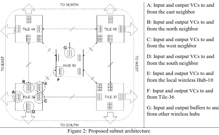
A: Input and output VCs to and from the east neighbor
B: Input and output VCs to and from the north neighbor
C: Input and output VCs to and from the west neighbor
D: Input and output VCs to and from the south neighbor
E: Input and output VCs to and from the local wireless Hub-10
F: Input and output VCs to and from Tile-36
G: Input and output buffers to and from other wireless hubs
Figure 2: Proposed subnet architecture
Figure 2 shows a zoomed in top-level view of view of the subnet-10 in figure 1. This figure shows
the arrangement between core tile and the wireless interface and how they are connected with each
[image:32.612.82.533.68.347.2]other. The diagram also shows the various VC buffers of the core tiles and the hub, and from the
figure it can be seen that each core tile has multiple input and output VC buffers for each direction
the core tile is connected to. The figure does not show the local processing element or its VC buffer
since they have to be present by default with each processing elements in the core tile. The VC
buffer plays an important role in the selection and routing of data packets in the system and number
and the size of each of these buffers will be discussed in detail further down this section. The
processing elements in the NoC is based on the type of application for which the NoC will be
implemented for and it can be either CPU, GPU, or DSP units or a combination of them. In this
thesis work all of the processing elements in the system is going to be considered as identical CPU
cores, in order to make a large multi-core CPU environment which can be seen in the researches
22
also makes the calculation for the number of clock cycle required for data to processed and
transmitted more predictable.
3.2: Wireless interface physical layer
In this section we will look into the design of the proposed antenna and the transceiver for the
hybrid WiNoC system presented in this thesis work. As discussed in Chapter 1 on-chip antennas
are required to establish links between the wireless hubs in the proposed hybrid NoC system.
Furthermore, the proposed on-chip antenna has to provide the maximum power gain with the least
amount of area overhead. Previously it was seen that various research has designed and effectively
implemented different kinds of antenna for their WiNoC research. Out of the three antenna designs
discussed above, the proposed hybrid NoC system for this thesis work is going to consider the use
of mm-wave antenna in all of the wireless hubs. Research done in [17 - 19] has shown that the use
of zig-zag mm-wave antennas with non-coherent OOK modulation scheme in the transceiver
shows the best performance for current CMOS technology in terms of reliability, throughput and
energy efficiency. Furthermore, the mm-wave has a transmission range of 20 mm which means
[image:33.612.170.448.515.630.2]that long range communication within the chip will not be an issue.
Figure 3: proposed zig-zag antenna placement on the die [52]
A. On-chip antennas: The metal zig-zag antenna which was shown to provide the best power
23
those criteria, this thesis work utilizes the same antenna design as done in previous work
[52] since it adopts an on-chip mm-wave zig-zag antenna tuned to 60 GHz operating
frequency with a bandwidth of 16 GHz. As shown in figure 3 the on-chip mm-wav zig-zag
antenna is based on the co-planar feed structure as it has low-losses compared to other feed
structures such as microstrip. Furthermore, this type of antenna was seen to be
non-directional [53] which makes the wireless medium in the system a shared channel.
(a)
(b)
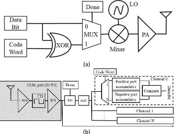
Figure 4 (a) Transmitter (b) receiver block diagram
B. Wireless Transceiver Circuit: For the system to have a high throughput and low energy
with the least bit error rate, this thesis work adopts the non-coherent on-off keying (OOK)
modulated transceiver design to go with the above proposed on-chip antenna. Figure 4(a)
and (b) shows the proposed transmitter and receiver circuit block diagram respectively,
that will be used for the wireless communication in this thesis work.
As mentioned in section one, this thesis work utilizes a two state MAC operation based on
whether the WIs are trying to communicate core or control data. Considering the different
[image:34.612.208.515.241.477.2]24
mode. In addition to the OOK modulator in [54] and the demodulator in [55], a
orthogonal-code enorthogonal-coder and deorthogonal-coder is added to the design to support the congestion information
(control data) transmission during the control mode.
In control mode, the congestion data bits are first encoded by XORing it with a
transmitter-specific code word. In this thesis work a Walsh code-based communication is adopted for
the control messages during the control mode. The encoded control data or the unencoded
core data (during data mode) is then modulated with the 60 GHz carrier generated by the
Voltage Control Oscillator (VCO) by an OOK modulator and then the resulting signal is
then amplified using the power amplifier (PA). Once the signal has been amplified the
resulting signal is then coupled to the on-chip antenna, to be transmitted to the destination
WI(s). Furthermore, the wireless channel is assumed to be an additive multipath channel
which means that individual transmission encoded into different codes are added over the
channel.
On the receiver side, the received signal is first amplified by the Low Noise Amplifier
(LNA), then this signal is sent to the Envelop Detector (ED), which will strip of the actual
signal from the carrier frequency signal. The core signal is then amplified by a base-band
amplifier (BA). Based on the operation mode the next step for the incoming signal will be
decided. If the data transmitted was during the data mode then no further action is required
and the received data can be transmitted to the destination core tile, thus only employing
the first part of the receiver circuit boxed in grey as shown in figure 4(b). But if the data
was transmitted during control mode the received data are from all other WIs in the system,
thus the receiver needs to have additional decoders for every transmitter-specific
25
is further sent to a code decoder. An Analog-to-Digital Converter (ADC) converts the
received envelop from the additive multi-path channel into digital signals. Then, the signal
is correlated with each code word from the code book to create separate receiving channels
corresponding to every code word. The digital signal enables the adoption of a digital
correlator receiver that accumulates and compares the positive and the negative part of the
received symbols to compute the received digit for each channel [56]. Since all the
transmitter in the system has its own predetermined code word, a single receiver can
receive data from multiple transmitter simultaneously. A Power Gating (PG) cell,
controlled by the “Done” signal generated based on the operation mode (see next
subsection for more details), separates the receiver circuitry and the orthogonal-code
decoder circuits. The PG cell selectively turns on and off the part of the receiver based on
the operation mode. Furthermore, the PG cell also helps to improve power efficiency of
the transceivers in the WiNoC system.
Lastly it is shown in [54, 55] that such OOK modulator –demodulator design achieves a
very high spectral efficiency over the 60 GHz carrier, providing a physical data rate of 16
Gbps in a point-to-point link at total energy consumption of 2.075pJ/bit. The
signal-to-noise (SNR) for these wireless links are given by:
SNR = PT – PL – Nf (1)
Where PT is the transmitted power, PL is the path loss and Nf is the noise floor of the
receiver (all in decibels (dB) units). However, as noted in [57], the Bit Error Rate (BER)
of such chip-to-chip wireless interconnects is governed by Inter-Symbol Interference (ISI)
due to the high-speed transceivers and antennas being bandwidth limited and is 10-15 for a
26
3.3: Operation modes
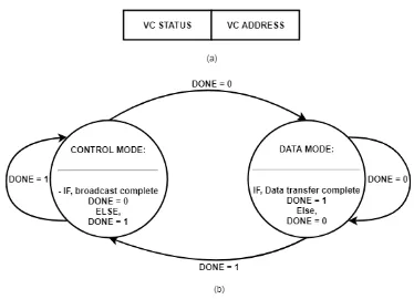
Figure 5 (a) Control packet (b) State diagram
As mentioned in the earlier sections the proposed WiNoC system consists of two operation modes
each consisting of its own MAC protocol. In this subsection, the switching between these two
protocols will be discussed in details.
The “Data Mode” as mentioned in the previous section is the mode when the WiNoC system is
utilizing both its wired and wireless medium to communicate core data with other core tiles. From
figure 2 it can be seen that each subnet consists of a single WI and four core tiles and all of the
modules are connected using wireline links and bidirectional ports. For the wireline links, a
wormhole switching technique is adopted where data packets are broken down into flow control
units or flits [58]. The wormhole switching was chosen because it provides low buffering
requirements and high network utilization through the use of VCs. For the wireless links, the same
wormhole switching principle is used but with a modified flow control which will discussed in the
[image:37.612.118.492.89.359.2]27
used to establish on-to-one communication between the source WI (who is holding the token) and
the destination WI.
The “Control Mode” as mentioned in the previous section is the mode when the WiNoC system is
utilizing only the wireless medium to communicate the network congestion information in the
system. Adopting a token-based MAC protocol similar to that of that used in the data mode will
introduce overheads and reduce effective bandwidth for the data transfer. Since one of the goals
of the thesis is to create a system which has global traffic awareness, each WI needs to share its
local congestion information with all the other WIs by broadcasting it at the same time. Therefore,
in this thesis the orthogonal-code based MAC protocol is used, which is capable of supporting
multiple broadcast transmission simultaneously for such control message transmission. The
transmitter and receiver designs of such systems was discussed in the previous subsection. During
the data mode the control data is XORed with the code word unique to that WI and then transmitted
simultaneously to all the other WIs in the system. The issue with using orthogonal-code based
encoding technique is that as the size of such system increases the effective wireless bandwidth is
reduced and the average packet latency increase with the increase in code length. The number of
cycles for such broadcasting transmission can be given by the general equation:
T = N * V * Fclk / G (2)
Here, T is the number of cycles for transmission, N is the total number of WIs in the system, V is
the control message length in bits, Fclk is the clock frequency of the system in GHz and G is the
aggregate wireless bandwidth in Gbps. Furthermore, the control packet for such system has to be
as small as possible in order to maintain a lower packet latency and use the limited bandwidth of
28
From the previous chapters and subsection it has been established that in “Control Mode” the
network congestion information is broadcasted using only the wireless links with the help of
orthogonal-code based MAC policy. Each control packet contains VC status information for the
transmitting WI. The broadcasted congestion information needs to communicate the following
information to establish an effective global congestion awareness: (a) The address of the WIs, (b)
The VC buffer status of each WI, and (c) The address of the free VC buffer in each WI. Since the
information needs to be broadcasted using orthogonal-code based encoding technique, the control
packet for such system has to be as small as possible, in order to maintain a low latency. For such
reason the address of the WIs will not be broadcasted since in orthogonal-code based MAC policy
assigns a unique communication channel for each WI. Thus each WI can be assumed to be aware
of the identity of the other WIs in the system by associating the channel to a particular WI.
Figure 5(a) shows the control packet that each transmitter broadcast during control mode. The first
field of the control packet contain the VC status bit which is a 1-bit field. When the VC status bit
is high, it signifies that the WI from which the corresponding control packet came from has no
empty VC buffer and in the next data mode the WI corresponding to that control packet will not
be used to transmit core data wirelessly from other WIs in the system. If the VC status bit is low
it means that there is one or multiple free VC buffers available for wireless transmission in data
mode, the second part of the control packet which contains the VC address will be used as the
destination buffer for the wireless transmission in the data mode. For this thesis work, the designed
hybrid WiNoC system has 4 VCs per input and thus only take 2 bits to represent the VC address.
If multiple VCs are empty, the VC having the lowest address value is considered. Even though
multiple VCs can be free for a given WI, the control packet will only consider one VC in order to
29
Thus, based on the control packet structure and the equation (2) described above, it can be inferred
that for a system shown in figure 1 with 16 WIs, running at 1 GHz frequency, the data mode would
require 3 cycles to transmit all the control information with all the WIs in the system and then
return to the data mode for normal one-to-one data transmission. Since the two modes utilizes two
different MAC protocol, the two state MAC operation can be realized into a hybrid MAC protocol
controlled using a “DONE” signal as shown in figure 5(b).
In data mode the token-based MAC protocol is used to establish a one-to-one communication
between the source WI (the token holder) and the destination WI. The token period Tp in this data
mode is defined as the round-trip time for a WI to get the token back once it finishes its
transmission. Once a WI finishes it transmission after an epoch of Y cycles (where Y = Tp/N), it
passes the token to the next Wi and then the done signal goes high which marks the transition of
the system from the data mode to control mode. Once in the control mode all the WIs updates and
share its VC buffer status with all other WIs in the system for T cycles (given by equation (2))
using the orthogonal-code based MAC protocol. Once the broadcast is completed the done signal
goes low and the system once again transitions to data mode. The amount of time the “DONE”
signal is in data mode depends on the data packet length the source WI is trying to transmit. Thus,
the “DONE” signal can be can be thought of as a logical OR implementation of a cycle and flit
counter in the data mode whereas in the control mode, it resets purely based on the cycle count
given by equation (2). To keep the simulation more predictable and also ensure the system is
robust, this thesis work will consider the packet size to be fixed in size and the buffer depth for
each VC equal to the packet size in terms of flits per packet. In doing so, the proposed hybrid MAC
30
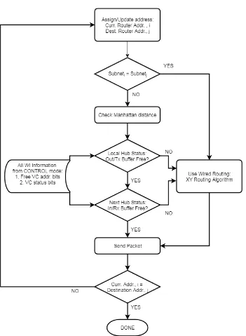
3.4: Routing scheme and controller design
Figure 6: the routing scheme flowchart
In a hybrid WiNoC system such as the one presented in this work, a contention free routing scheme
must be developed in order to maintain high network utilization by using both the wired and the
wireless path. Without the use of proper contention free routing algorithm data packets will always
31
source and destination core tiles. This causes the wireless line to be heavily congested even in low
traffic applications and the wired paths remain underutilized. For this reason, this thesis work
proposes a dynamic routing scheme for the data mode which is based on existing routing scheme
and also with the help of the network traffic information gained during the control mode create to
create a load balancing routing scheme which utilizes both the wired and the wireless path in the
proposed hybrid WiNoC.
Figure 6 shows the proposed routing scheme flow which will be used during the data mode for the
proposed hybrid WiNoC. Once a data packet is generated by the processing element, the core data
is packetized and a header flit is added to the data packet. In the header flit the current and the
destination address for the message is assigned. Each current and destination address is divided
into two parts. The first part of the message contains the subnet address which is common to all
the core tiles in a given subnet and the second part contains the address of a specific core tile in
the subnet where the message needs to be sent. Based on the proposed routing scheme, if the
current subnet address of the message is equal to the message’s destination subnet address, the
message is being transmitted between two core tiles in the same subnet and the wired path will be
selected for its transmission. In the proposed hybrid WiNoC all inter-subnet communication will
be done via the wired links since the Hybrid WiNoC allows one hop communication via wired
links between the core tiles and the shared central WI (as shown in figure 1 and 2).
If the message’s current subnet address is not equal to the destination subnet address, a second
stage calculation is done by the router to determine the most optimized path for the packet based
on the global traffic congestion map which contains the VC status of all the WIs in the system.
The VC status of all the WIs are updated during the control mode and based on this and the routers
32
distance between the current and the destination core tile. If the router sees that the destination WI
has free VC buffer then the message will be sent via wireless path in a one hop communication. If
the destination WI VC buffer is not free, the router first calculates the worst-case Manhattan
distance which is the maximum number of hops required if the message takes only wired path
from the current tile to the destination tile. In the next stage the router checks if transmitting the
message to any nearby WI reduces the distance, such that the effective number of hops are reduced
from the intermediary WI to the destination. If there is such an intermediary WI, the message is
sent to that intermediary WI and the current router address is updated and the done signal goes
high to start the control mode. If no such intermediary WI is found the router transmit the packet
via the wired link to the next core tile updating its current address and trying again for the WI in
the next data mode after the control mode for this current cycle completes. All this routing scheme
calculations are done in the individual router connected to each core tile in the proposed hybrid
WiNoC system. Furthermore, a more detailed routing scheme and the selection strategy for the
33
Figure 7: Block diagram for the router architecture.
The routing scheme described above utilizes the router at each core tile which carries out the
non-trivial task of finding out the most optimized path for a data packet to take during the data mode.
Figure 7 shows the block diagram of the router architecture which needs to be implemented for
the proposed hybrid WiNoC in this thesis work. From the figure it can be seen that each tile has
an input and an output buffer space for each direction the router needs transmit the data. When a
new header flit is seen, the address decoder decodes the destination address and sends it to the
router controller which controls all the input and output port access. Here in the router controller
the routing scheme algorithm is implemented in hardware and based on the congestion information
34
makes it decision on which direction the packet needs to be routed. The port controller then sends
a connection request to the crossbar arbiter in order to set up the path to the corresponding output
port for the data packet to take. Another reason for the crossbar arbiter is that to ensure that all
input buffers from each direction gets equal access opportunity to the router controller based on a
first come first serve basis. During control mode the crossbar arbiter stops any access to the output
ports and wireless a separate wireless channel is used to broadcast and receive the global traffic
congestion information and update its own global WI congestion map. Once the global WI
congestion map is updated the system goes transitions to the data mode again and once again the
crossbar arbiter and the router controller resumes its normal operations.
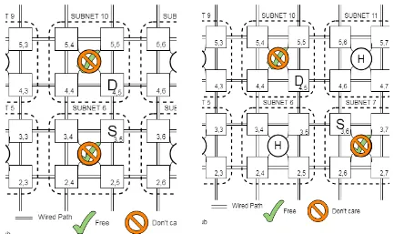
3.5: Example operation
To have a better understanding of the routing scheme and the selection strategy for the
communication in the data mode, this subsection is going to present some case scenario based on
which the router will mathematically calculate and logically decide which path will be most
optimized for the data packet to take during the data mode. Since the proposed hybrid WiNoC has
a mesh-based architecture, all the core tile can be assumed that they are equally far apart and each
of their location can be coordinated as shown in figure 1. Since for a given system size the
coordinates of the core tile are fixed, the router at each tile then have the wired path only Manhattan
distance information from its own tile to all the corresponding core tiles in the system. Using this
information and also the network traffic information the router will decide on the most optimized
path based on the algorithm explained above.
The Manhattan distance between two points is defined as the sum of the horizontal and vertical
![Figure 3: proposed zig-zag antenna placement on the die [52]](https://thumb-us.123doks.com/thumbv2/123dok_us/25608.1989/33.612.170.448.515.630/figure-proposed-zig-zag-antenna-placement-on-the.webp)