Evolution of constrained layer damping
using a cellular automaton algorithm
C M Chia, J A Rongong*,andK WordenDepartment of Mechanical Engineering, The University of Sheffield, Sheffield, UK
The manuscript was received on 19 February 2007 and was accepted after revision for publication on 27 November 2007.
DOI: 10.1243/09544062JMES638
Abstract:Constrained layer damping (CLD) is a highly effective passive vibration control strat-egy if optimized adequately. Factors controlling CLD performance are well documented for the flexural modes of beams but not for more complicated mode shapes or structures. The current paper introduces an approach that is suitable for locating CLD on any type of structure. It fol-lows the cellular automaton (CA) principle and relies on the use of finite element models to describe the vibration properties of the structure. The ability of the algorithm to reach the best solution is demonstrated by applying it to the bending and torsion modes of a plate. Con-figurations that give the most weight-efficient coverage for each type of mode are first obtained by adapting the existing ‘optimum length’ principle used for treated beams. Next, a CA algor-ithm is developed, which grows CLD patches one at a time on the surface of the plate according to a simple set of rules. The effectiveness of the algorithm is then assessed by comparing the generated configurations with the known optimum ones.
Keywords: passive vibration control, vibration damping, constrained layer damping, cellular automata
1 INTRODUCTION
A common way to reduce vibrations in plate, shell and other thin-walled structures is to apply surface damping treatments. When the damping treatment is applied as a single-layer coating, sometimes known as free layer damping, the principal energy dissipation mechanism involves direct, in-plane strains induced in the damping material. Viscoelastic polymers operating in the transition zone are often used as the damping material as they have a high material loss factor [1].
Significant increases in energy dissipation can be achieved by attaching a stiff layer known as the con-straining layer (CL), on top of the viscoelastic layer (VL). This occurs because large shear strains are gen-erated in the damping material. To be effective, how-ever, such constrained layer damping (CLD) systems
must be optimized in terms of materials used and configuration of the treatments applied. Key par-ameters controlling performance were identified sev-eral decades ago using analytical models developed for slender beams [2–5]. Since then, many studies have been carried out to improve the damping of structures, fully or partially covered with CLD. Exist-ing theoretical understandExist-ing is adequate for opti-mizing CLD for the flexural vibrations of beams. However, in structures consisting of plate and shell-like elements, vibration mode shapes can differ con-siderably and hence the approach has to be more general.
The desire to apply CLD to more complicated structures has encouraged researchers to consider global optimization methods in conjunction with finite element (FE) analysis. The genetic algorithm (GA) for example, has been used in several CLD design studies [6–8]. This approach [9,10] is based on the notion of ‘survival of the fittest’: within a popu-lation of feasible solutions, those yielding the best results are retained to the next generation while the poor solutions are eliminated. The GA is a powerful *Corresponding author: Department of Mechanical Engineering,
global approach but is computationally expensive for FE-based optimization because of the large number of possible treatment locations.
An alternative optimization approach involving FE analysis is the use of algorithms based on cellular automata (CA) principles [11]. During the last two decades, CA algorithms [12–14] have been used to simulate biological phenomena, which are well known for having an intrinsic optimization schedule. Thus, by mimicking the evolution of the biological phenomena, it is possible for CA to drive a physical system towards its optimum. For example, Wardle and Tomlinson [15] used CA, inspired by cell growth in living organisms to locate a free layer damping coating on a vibrating plate in a more effi-cient manner. As the optimum location of a free layer coating is dictated by the surface strain on the host structure, its optimization is therefore reason-ably intuitive. The current paper instead, considers the use of CA in optimizing the more challenging case of CLD where several different parameters con-trol the performance. Note that this study does not discuss one of the most obvious ways to improve the performance of a CLD treatment, namely to increase the loss factor of the damping material itself. Instead, it focuses on achieving a configuration that uses a given material as effectively as possible.
The structure of this paper is as follows: important and relevant findings reported in the literature regarding CLD and the CA approach are briefly described in sections 2 and 3 respectively; section 4 contains a description of the way in which the per-formance of the model used in this study is evaluated and includes optimum CLD for a representative but easily defined case (namely first bending and torsion modes of a plate); an appropriate algorithm utilizing CA is introduced in section 5 and its performance is tested by applying to the plate; finally, conclusions regarding the suitability of the CA approach for this problem and possible future studies are summarized in section 6.
2 OPTIMIZATION OF CLD
Over the years, many have studied the optimization of CLD on beam-like structures. Energy dissipation in CLD occurs through deformations induced in the viscoelastic material (VEM). In most cases, shear is the dominant mechanism. Though high levels of damping can be achieved where out-of-plane defor-mations occur, this regime occurs in a relatively narrow (and unusual) design space, which is easy to define [16]. It is therefore not considered further here. Instead, this section briefly considers relevant findings in the literature regarding the optimization of shear-dominated damping.
Analytical work on beams treated with CLD [2–5] has identified two parameters that govern damping effectiveness. The geometric parameter is related to the stiffness increase caused by the addition of the CL. It controls the maximum damping achievable. For most commonly used configurations of conven-tional CLD, the geometric parameter can be simpli-fied to show that
hHhv
Ectc
EhthþEctc
ð1Þ
wherehis the modal loss factor,Ha constant,hvthe
material loss factor at the specific frequency and temperature,Ethe Young’s modulus,tthe thickness, and the subscripts h and c refer to the host structure and CL, respectively.
The shear parameter is the relative shear stiffness of the damping layer normalized by the extensional stiffness of the CLs. The effectiveness of CLD is extre-mely sensitive to this parameter and its optimization has been the focus of several papers [5,17,18]. For example, in 1987, Lifshitz and Leibowitz [18] devel-oped a numerical program to optimize the uniform thickness of each layer of a beam for a large variety of boundary conditions. Note that the shear par-ameter does not alter the maximum damping achievable – its value controls whether or not the maximum (for a given geometric parameter) is achieved.
In the literature, the shear parameter is expressed in a number of different ways as researchers adapted its definition to suit the needs of their particular study. In order to avoid confusion, in this work refer-ence will instead be made to the stiffness ratio, C, which is defined as
C¼ shear stiffness of VL
in-plane stiffness of CL¼
GvL2c
Ectctv
ð2Þ
where G is the shear modulus, L the length, t the thickness, and subscripts v and c refers to the visco-elastic and CLs, respectively. Note thatCis identical to the shear parameter used in a number of other works [19,20], and is generally used when the CL is relatively flexible in comparison to the host structure. By considering a CLD treatment attached to a host structure under uniform strain, Plunkett and Lee [19] showed that an optimum configuration occurs when
treated with different sized patches of CLD has shown that optimum performance on plate bending modes is achieved for the same range ofCvalues [21].
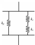
To help with the design of CLD for box-section beams, Marsh and Hale [22] introduced the three-spring model shown in Fig. 1. They set kvto be the
shear stiffness of the VL andkcto be the in-plane
stiff-ness of the CL. It can be seen that the stiffstiff-ness ratioC
used in the current paper is equal tokv/kc.
The reliance of damping performance on treatment location and coverage area has been demonstrated numerically for beams [23, 24], frames [25] and plates [21, 26]. The optimum location occurs where the surface strain energy of the host structure is high-est (i.e. at point of high modal curvature). By altering the thickness of an initially uniform VL, Lunden [23] showed that a non-uniform distribution could improve performance – amplitude reductions of 40 per cent are reported. An optimization approach that allowed both treatment layers (CL and VL) to be redistributed is presented by Lumsdaine and Pai [27]. They applied the sequential quadratic program-ming (SQP) algorithm to a treated beam and showed that for a fixed amount of VEM coverage, there exists an optimum thickness for the base layer of the CLD structure.
For the context of the work presented here, import-ant findings from the literature are given below.
1. The stiffness of the CL and the loss factor of the VL are the most significant parameters that affect the maximum damping achievable.
2. It is usually desirable to locate CLD at points of high modal curvature.
3. The stiffness ratio (C) controls the efficiency of a given CLD treatment. It is a function of the thick-ness and moduli of both layers in the CLD treat-ment and thus controls factors such as the optimum patch size.
In practice, a designer often has a limited choice of CLD materials available due to environmental factors (thermal and chemical), fabrication issues (for example, doubly curved surfaces) and the fact that commercial CLD is supplied in a few preset thickness combinations. As a result, optimized performance is not always the main factor affecting the decision
regarding the nature of the treatment chosen. Thus to provide good performance, it is important to select carefully, the correct shape and location of the treatment to be applied.
3 CA ALGORITHMS
Biological phenomena are well known for their intrin-sic optimization schedules. In fact, over the last 30 years or so, biological metaphors have proved invalu-able in the design of powerful computational pro-cedures for optimization. The most well known example of this is of course the genetic algorithm and its various evolution-based variants [9]. More recent developments include the Ant Colony Meta-phor [28] and various approaches motivated by the human immune system [29]. In fact, despite the fact that these algorithms are formally optimization routines in the sense that they aim to maximize or minimize a given objective function, there is now a body of evidence that nature does not always seek to optimize. Ben-Haim [30], among others, argues that in many cases, nature will not actually seek to optimize, but will rather seek a solution which simply satisfies appropriate performance criteria. This strategy of ‘satisficing’ rather than optimizing has the significant advantage that it can provide sol-utions, which are robust against uncertainty in the specification of the problem; it can be proved for-mally that ‘optimal’ solutions are fragile against uncertainty [30]. The cellular automata approach dis-cussed in this paper falls into the class of algorithms which satisfice rather than optimizing; the algorithm in this case is designed to drive the solution towards a satisfactory performance rather than optimizing a formal objective.
[image:3.595.136.209.76.169.2]systems. In fact, it is known that particular CA schemes are Turing machines and thus universal computers [14].
Often, this complicated system is homogeneous in terms of complexity of its constituent processes, i.e. the rules for evolution of the individual cells are the same throughout the organism. This is the case for bone.
Formally, a CA is a mathematical idealization of a physical system in which space and time are discrete [14]. The design domain is divided into a lattice of cells, each one capable of performing only a set of simple operations. Also, each cell may be in one of the finite number of states, S. These states are updated synchronously in discrete time steps, t, according to identical local rules,R; and these rules depend on the present states of the cell and its neigh-bours within a certain proximity (neighbourhood). Equation (3) shows the evolution of the state of each cell at discrete positionr, whererþDdesignates the cells belonging to a given neighbourhood of the CA
Sðr;tþ1Þ ¼RðSðr;tÞ;SðrþD1;tÞ;. . .;SðrþDN;tÞÞ ð3Þ
Figure 2 shows commonly used CA neighbour-hoods. The CA neighbourhood does not have any restrictions on size or location, except that it has to be the same throughout the entire lattice. The lattice structure, however, is not limited to regular shape; an irregular shape of lattice is also possible (in this case, the neighbourhood is defined in terms of connectivity rather than ‘shape’). The class of algorithms specified by the rule of equation (3) is very large and encom-passes, among others, the class of finite difference algorithms used to evolve the solutions of partial differential equations.
The principle of a CA-based algorithm is that over-all global behaviour of a system can be computed by cells that only interact with their neighbours based on local conditions. In general, because of their univer-sal nature [14], it is possible to simulate any system using CA by modifying the structural and local
rules; where the structural rules are the shape of the cell, number of dimensions, and the type of neigh-bourhood. One can approach the construction of a CA model for a given problem in two ways. In the first approach, one has a non-formalized task, which requires a thorough understanding on the nature of the corresponding problem and some experience in dealing with CA. In the case of bone remodelling for example, the approach would be to generate rules, which encapsulate the engineering objective of preserving strength while controlling weight. This is the approach taken here. A more formal approach is based on a type of system identi-fication where rules can be learnt from data [12].
In the current paper, an algorithm based on the CA principle is used to locate CLD treatments on a plate with free boundary conditions. The effectiveness (damping per unit added mass) is evolved in accord-ance with appropriate performaccord-ance criteria for the lowest vibration modes of the plate. Starting with a single cell, the approach used causes the CLD patch to grow until a satisfactory size and location are achieved. While the process is not formally one of optimization, one can obtain solutions better than those previously observed in the literature, simply by making the performance criteria appropriately stringent.
4 DEVELOPMENT OF AN APPROACH TO TEST THE EFFECTIVENESS OF CA FOR CLD
As this piece of work aims to show how the CA approach can be used to assist in the design of CLD treatments for general structures, care has been taken to ensure that methods used are readily avail-able and resource-efficient. To achieve this, the approximate modal strain energy method [32], in conjunction with a commercial FE analysis software package, is used to estimate the performance of CLD treatments considered. It is important to note, however, that the CA method described in this paper is equally compatible with more accurate cal-culation methods: the CA rules do not depend on the method chosen to evaluate the cost function. This section provides an explanation of the modelling approach used and the basis for testing the perform-ance of the developed algorithm.
The host structure chosen for this study is a rectangular plate with free boundaries. The reason for this choice is that a plate provides a good compro-mise between a system with independently verifiable optimum coverage and the need to apply the CA approach to a structure with a two-dimensional dynamic strain field. The lowest frequency vibration modes of plate-like structures involve out-of-plane, flexural deformations. Two types of mode shape are Fig. 2 Commonly used neighbourhoods; hatched areas
[image:4.595.51.263.640.737.2]most common: those for which all node lines are parallel and those for which at least one node line is perpendicular to the others. For ease of identifi-cation, these are referred to as bending and torsion modes respectively in this paper.
The plate is modelled using quadratic FEs: eight noded offset shells are used to represent the host structure and CL while the viscoelastic material is modelled using 20 noded solid elements. While many researchers have developed special shell elements for more efficient modelling CLD on struc-tures, these are not used here because they are cur-rently not available in general purpose commercial FE code. The chosen FE mesh gave a grid of 10
10 mm2elements on the surface of the plate. This is the result of initial studies aimed at achieving a com-promise between the need for computational efficiency and the need to get good calculation accu-racy and spatial resolution for the CA. Dimensions and materials properties for the host structure and CLD treatment are given in Table 1.
A variety of different approaches can be used to represent the viscoelastic properties of the damping material. While it is well known that the complex modulus of a viscoelastic material varies dramatically with temperature and frequency, most analytical work is carried out under isothermal conditions. In the work presented here, the complex modulus is also assumed constant over all frequencies. For the purposes of demonstrating the CA approach and when vibration modes are considered individually, this is a reasonable simplification as the exact design of CLD rarely changes natural frequencies by more than 10 per cent. The consequences of ignoring this change are minimal as the level of uncertainty arising from material characterization (including batch variability and the use of the temperature – frequency superposition method) is usually at least 20 per cent. However, should several vibration modes spanning a significant frequency range be considered simultaneously, a calculation strategy that takes frequency dependence in to account would be necessary.
The final approximation is associated with the use of the modal strain energy approach itself. It is well
known that this approach, in its simplest form, can provide overestimates of damping and underesti-mates of natural frequency for systems with high material loss factors (hv) as it ignores the complex
part of the stiffness matrix during the eigenvalue extraction routine. When applied to a CLD patch, the approximation leads to an underestimation of the magnitude of the stiffness ratio C. For example, a typical polymer used in CLD is ISD112 (from 3M) whose material loss factor hv, at room temperature,
is in the range 0.8 to 1 depending on the frequency. Equation (2) implies that the optimum length of a given patch might be overestimated by no more than 20 per cent if the effect of material loss factor is ignored. This is consistent with reports in the litera-ture that the optimum length is only weakly depen-dent on the loss factor of the VL [19,20]. Methods for improving the accuracy of the modal strain energy approach are described elsewhere [33, 34] and can easily be used if required. However, in the work presented here, this is not considered necessary as the aim is to demonstrate the CA approach.
To allow direct comparison between patches of different size, the effectiveness of a particular CLD treatment is quantified as the loss factor ratio per unit added mass. The Modal Strain Energy approach gives
Loss factor ratio¼ h
hv
¼ Uvisc
Utotal
ð4Þ
whereh is the modal loss factor, Uvisc is the modal
strain energy in the VL and Utotal is the total strain
energy for that mode.
In order to assess the ability of the CA approach developed to generate satisfactory treatments, identi-fication of the characteristics of a weight-efficient coverage is necessary. The general 3-spring model of Marsh and Hale [22] (see Fig. 1) suggests that an optimum stiffness ratio exists for modes of any struc-ture treated with CLD. While there is abundant infor-mation relating to the optimization of flexural modes for beams (and hence by analogy, a reasonable start-ing point for the plate bendstart-ing modes), guidelines for the optimization of CLD for plate torsion modes are not available in the literature. This section therefore contains a brief study in which the concept of the optimum stiffness ratio is applied to bending and tor-sion modes in plates.
[image:5.595.53.296.659.761.2]CLD treatments are located near the centre of the plate and calculations are carried out to understand the effect that patch size and VL modulus had on the damping performance achieved. Practically this is achieved in the FE analysis by altering the Young’s modulus of the VL (and hence the shear modulusGv).
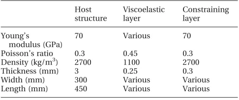
Table 1 Geometric and material properties used
Host structure Viscoelastic layer Constraining layer Young’s modulus (GPa)
70 Various 70
Poisson’s ratio 0.3 0.45 0.3
Density (kg/m3) 2700 1100 2700
Thickness (mm) 3 0.25 0.3
Width (mm) 300 Various Various
For the plate studied, the second and fourth modes had deformations similar to beam flexure modes. Figure 3 shows the damping effectiveness for mode 2 (first bending mode) when the treatment length is 60 mm and the width varies from 40 to 100 mm. It can be seen that an optimum shear modulus exists near Ev¼40 MPa. It can also be seen that the
opti-mum modulus is independent of the width of the treatment. This is consistent with expectation as bending occurs along the length of the plate for this mode. It is interesting to note, however, that the peak damping effectiveness decreases somewhat as the width of the treatment increases. Thus, for bend-ing modes, a thin strip of dampbend-ing treatment is more efficient for a given added mass.
Figure 4 shows the equivalent plot for the damping effectiveness of mode 4. In this case, the optimum modulus varies as the bending is in the width
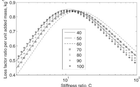
direction (perpendicular to mode 2). For the opti-mum stiffness ratio,C, to be constant, optimum mod-ulus values should relate to patch width according to equation (2). For this mode it is reasonable to assume that the limits of the patch in the width direction give the ‘effective length’. Figure 5 shows the damping effectiveness plotted against the value ofCcalculated in this way. It can be seen that the curves for different patch sizes overlay one another as expected. It can also be noted that the peak effectiveness occurs near C¼10, similar to the results reported for beams [19].
The plot showing damping effectiveness against VEM modulus for the first torsion mode (mode 1) is presented in Fig. 6. Comparison with earlier figures shows that the peak damping obtained for the torsion mode is around 35 per cent lower than that for the bending modes. However, the similarity between the torsion and bending curves – the presence of an Fig. 3 Damping effectiveness against VEM Young’s
modulus for mode 2 (first bending mode in length direction) with treatment length 60 mm and width varying from 40 to 100 mm
Fig. 4 Damping effectiveness against VEM Young’s modulus for mode 4 (first bending mode in width direction) with treatment length 60 mm and width varying from 40 to 100 mm
Fig. 5 Damping effectiveness against stiffness ratio C for mode 4 (first bending mode in width direction) with treatment length 60 mm and width varying from 40 to 100 mm
[image:6.595.302.539.75.232.2] [image:6.595.43.278.80.234.2] [image:6.595.261.533.547.704.2]optimum modulus value – suggest that the 3-spring model, and therefore the concept of optimum stiff-ness ratio, is also valid for plate torsion modes. How-ever, the appropriate mathematical representation forkvandkcfor the torsion mode is not obvious.
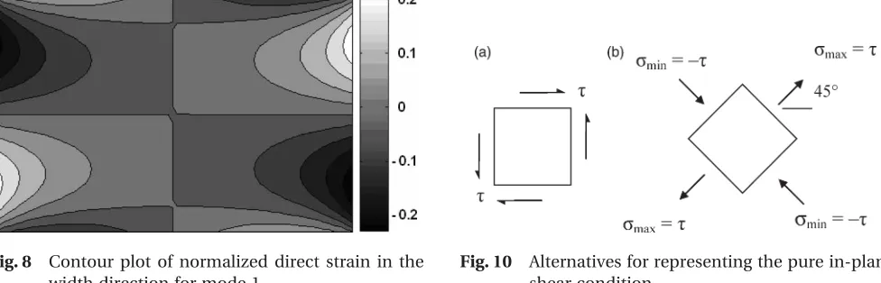
In an attempt to improve understanding of CLD behaviour in the torsion mode, the surface strain on the host structure is examined. Plots showing nor-malized in-plane direct and shear strains are pre-sented in Figs 7 to 9. These figures show that the centre of the plate is subject primarily to in-plane shear strain while the edges experience direct strains associated with local out-of-plane bending. Shear strain levels are around five times higher than those for direct strains. This is in contrast to the bending modes where direct strains in the bending direction dominate.
The CLD configurations suitable for structures sub-jected to in-plane shear have been reported for cylindrical shafts subjected to torsional vibrations [35]. As shear stresses acting on an element can be transformed to direct stresses at 458 [36] (see Fig. 10), helical strips of CLD are found to be effective for shafts. In the same way therefore, one can expect that CLD strips oriented at 458would be effective in damping plate torsional vibrations. It should
therefore be possible to obtain the optimum length using equation (2).
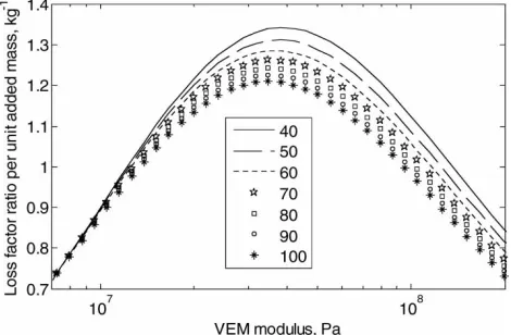
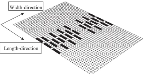
The above analogy is verified numerically by ana-lysing a smaller 100100 mm2 plate whose other properties are identical to the first one. For this study, the FE mesh density is increased: the length and width of each element is reduced from 10 to 1 mm. This allowed a CLD strip oriented at 458 to be represented with reasonable accuracy using a grid oriented at 08 (see Fig. 11). The strip is set to extend over seven elements in the width direction while the length is varied from 36 to 76 elements. (Note that actual length and width of the strip are obtained by multiplying the number of elements by
p
2.) The plate is then subjected to in-plane shear deformation and the loss factor ratio estimated from the strain energy levels in each layer of the system using equation (4). This calculation is repeated for different values of VEM modulus and strip length. Figure 12 shows the damping effective-ness against stiffeffective-ness ratio C. It can be seen that curves for different strip lengths overlay one another showing that the analogy is correct. It can also be seen that the optimum loss factor occurs when the stiffness ratio,C¼10, which is similar to that of the bending mode (see Fig. 5).
Fig. 7 Contour plot of normalized direct strain in the length direction for mode 1
Fig. 8 Contour plot of normalized direct strain in the width direction for mode 1
Fig. 9 Contour plot of normalized in-plane shear strain for mode 1
[image:7.595.315.554.79.210.2] [image:7.595.57.293.80.209.2] [image:7.595.60.548.598.755.2]One difference between the pure shear and bend-ing cases is that the pure shear element is subjected to a direct strain equal in magnitude but opposite in sense acting perpendicularly to the strip. This indi-cates that a strip subjected to shear of the host struc-ture will also have an optimum width. Unlike the bending mode where thin strips of damping treat-ment are most efficient for a given added mass, one could therefore expect wider strips of CLD to perform better for the torsion mode. This possibility is again tested using the model of the smaller plate described above. The length of the CLD strip is fixed at the opti-mum (36 elements when Ev¼14.2 MPa) and the
width increased from 10 to 40 elements. The
maximum damping effectiveness obtained is plotted against strip width in Fig. 13. It can be seen that the optimum width is approximately 30 elements.
The work on the small plate models uniformly shows that the patch extent in the direction of the principal strain is clearly the correct measure of Lc
[image:8.595.41.279.74.321.2]in equation (1). A final check is carried out by consid-ering the damping effectiveness for mode 1 (torsion) of the original (larger) plate as a function of stiffness ratio obtained using the effective length for shear strain. Results presented in Fig. 14 show that the curves for different patch sizes almost overlay. This indicates that the approach used is appropriate – the differences can be attributed to the fact that the tor-sion mode causes some bending as well as in-plane shear on the host structure.
[image:8.595.310.531.80.231.2]Fig. 11 Mesh showing plate subjected to uniform strain with CLD strip oriented at 458
[image:8.595.47.541.552.760.2]Fig. 12 Damping effectiveness against stiffness ratioC for plate subjected to pure shear with length of CLD coverage varying from 36 to 76 elements
Fig. 13 Damping effectiveness against treatment width for plate subjected to pure shear (when the length of the VEM coverage is 36 elements and the VEM modulus is 14.2 MPa)
[image:8.595.300.538.554.702.2]5 DESCRIPTION AND EVALUATION OF CA FOR LOCATING CLD
This section contains a description of an algorithm employing CA that locates CLD on a host structure, with an aim of maximize damping performance. Its effectiveness is evaluated by comparing results with those obtained using the stiffness ratio approach described in the previous section. To allow compari-son between the two methods, no changes are made to the host structure, mesh density, layer thickness, and material properties.
The algorithm presented here starts with an untreated structure. The aim of the algorithm is to build up a treatment on the surface of the host struc-ture by adding patches individually. The size, shape and location of each patch is optimized, though once its position is fixed, it is not altered. The CA rules that define this process are summarized below.
1. The procedure starts by adding one cell of the damping treatment (one element of CL on top of one element of VL) on the plate at the point of highest modal strain energy density. This locates the patch in the optimum zone on the plate. 2. The damping effectiveness (loss factor ratio
divided by added mass) is calculated using FE for four new patches each comprising the original cell plus one side of the von Neumann neighbour-hood. The configurations considered are illus-trated for a patch that is initially two cells in size as shown in Fig. 15).
3. The configuration with the highest damping effec-tiveness is selected for the next iteration. In this way, at each iteration, the patch extends in the direction that gives the greatest increase in effec-tiveness. As an example, the selected patch illus-trated in Fig. 15(f) assumes patch (c) gives the highest damping effectiveness.
4. The growth of a particular patch is terminated when addition of elements ceases to give an improvement in damping effectiveness, i.e. the effectiveness of all of the four new patches is less than that of the one selected in the previous iter-ation. A ‘stay-out’ zone is then activated around the completed patch in order to avoid overlapping
of subsequent patches. The Moore neighbourhood is used as the ‘stay-out’ zone in the work presented here. The procedure then continues by starting a new patch as described in section 1.
The stopping point for this iteration scheme can be selected by the user as a preset number of patches, a desired overall coverage, or a predefined damping level.
The above set of CA rules is applied to the plate model, one run each for the first two modes (bending and torsion, respectively). In this study, the modulus of the VEM is set to be 87 MPa (i.e.Gv¼30 MPa). In
each case, the procedure is terminated when 120 cells (out of a possible 1350) are activated – this relates to coverage of approximately 9 per cent. This level of coverage is achieved after approximately 200 iter-ations and is sufficient to show whether the evolved CLD treatment is similar to that expected using the concept of optimum stiffness ratio.
[image:9.595.318.552.78.199.2]Figure 16 shows the coverage obtained for mode 2 (first bending mode). The developed treatment takes the form of a series of thin strips, four elements in length, oriented along the length of the plate. For comparison, an ‘optimized’ coverage for mode 2 is also devised based on the findings from section 4. From the contour plot of the strain energy density for this mode (Fig. 17), it can be seen that the highest values (and hence best damping treatment locations) lie in a width-wise strip across the middle of the plate. In addition, a stiffness ratio of C¼0, gives an
Fig. 15 Steps involved in patch growth: (a) initial patch and neighbourhood; (b) – (e) different patches analysed; (f) new patch and neighbourhood
[image:9.595.81.528.646.731.2]optimum patch length of 42 mm (approximately four elements). Noting that for bending modes, narrow strips are more effective than wide ones, the configur-ation shown in Fig. 18 is obtained. Values of damping effectiveness achieved by each of these treatments are presented in Table 2. Both give values close to 1.3 for the bending mode. Comparison with perform-ance curves presented in section 4 shows that this value is the highest reached for bending modes. This shows that the algorithm presented is able to find the optimum configuration for the bending mode. Note that in both cases, the patches are four elements in length and one element in width. Not surprisingly, for these configurations, the damping effectiveness for the torsion mode is significantly lower (around 0.4).
The CLD configuration achieved when applying the CA to the torsion mode (mode 1) is shown in Fig. 19. The CLD treatment appears as a number of strips, each three elements in width, oriented either along or across the plate. It should be noted that the effective patch length in the direction of principal strain near the centre of the plate (at 458) is 42 mm – the same as would be predicted by the optimum
stiffness ratio. Damping effectiveness (Table 2) is around 0.8 for the torsion mode; a similar level to the best values observed for the rectangular patch in section 4 (see for example, Fig. 6). This is the best value achievable using patches oriented at 08or 908 to the plate; a condition enforced by the use of the von Neumann neighbourhood. For the bending mode, the damping level achieved by this configur-ation remains high (above 0.9) as the strip width is almost optimal.
In section 4, it is shown that for areas dominated by in-plane shear on the host structure, the optimum patch is nearly square and rotated through 458. CA evolution for the torsion mode (Fig. 19) shows strips that are far from square. This apparent inconsistency can be explained by considering the effective length of the patch in the direction of the principal strains. Figure 20 shows rectangular and square patches oriented at 458 to the strain direction in the host structure. It can be seen from the figure that much more of the rectangular patch is working optimally, i.e. having optimum length in the strain direction.
In simulations shown so far, the evolution is stopped when the coverage reached 120 cells. Figure 21 shows the evolution of the CLD coverage for the torsion mode up to 37 per cent (achieved after 800 iterations). It is interesting to note that the algorithm produces long strips near the centre, Fig. 17 Contour plot of SE density on the surface of the
host structure for mode 2 (heaving shading indicates low strain energy density)
Fig. 18 CLD coverage obtained for mode 2 using optimum shear stiffness ratio
Fig. 19 CLD coverage obtained for mode 1 using CA algorithm
Table 2 Comparison of damping effectiveness for different configurations
Approach used
Loss factor ratio per unit added mass
Mode 1 Mode 2
Optimum stiffness ratio for mode 2 0.408 1.295 Fig. 18
Cellular automata configuration optimized for mode 2
0.396 1.322 Fig. 16
Cellular automata configuration optimized for mode 1
where in-plane shear strain is the dominant host structure deformation. Away from the centre, where direct strains become more important, the patches are smaller, close to the optimum length suggested by the stiffness ratio.
The results show that highly efficient treatments can be built up relatively quickly. By comparison, a genetic algorithm that uses a realistic population size of 50 would get through only a few generations for the same number of FE runs. For example, 200 iterations (required for 9 per cent coverage using CA) would be achieved after only four generations while for reliable results, typically more than a hun-dred generations are required. Note that population-based routines are often preferred over more
traditional methods such as Downhill Simplex or Simulated Annealing for this type of problem as they are better at handling local minima.
One potential weakness of the CA approach is that it may lead to suboptimal results if the deformation around a given patch changes significantly on addition of new patches. While it is reasonable to assume that mode shapes do not change dramatically from adding CLD for most treatments, it may become a source of error when particularly thick or heavy CLs are studied.
6 CONCLUSIONS
The current paper has demonstrated numerically, the use of the CA approach to apply CLD treatments to structures. While work in this paper has used a plate with free boundary conditions as the host struc-ture in conjunction with the modal strain energy approach, the approach should work for any struc-ture and calculation method provided a reasonably regular FE mesh could be created. The approach has been shown to be well suited to problems where the CLD treatment is relatively thin compared with the host structure.
[image:11.595.58.293.77.182.2]In order to assess the ability of the algorithm based on CA to drive the solution towards an efficient cover-age, the effect of the configuration of CLD on the bending and torsion modes of the plate is studied. Fig. 20 Rectangular (a) and square damping (b)
treatment oriented at 458under tension in the horizontal direction (black shows treatment working optimally)
[image:11.595.92.515.453.728.2]Performance is shown to be controlled by the stiffness ratio (shear stiffness of VL divided by exten-sional stiffness of CL). For bending modes, it is shown that thin strips of treatment oriented in the direction of flexure are the best. For torsion mode, as the centre of the plate deforms primarily in shear, the optimum patch is approximately square and is rotated through 458.
The CA approach is shown to produce a near-optimal treatment for the bending mode. As the CA rule used did not allow the treatment to grow diagon-ally, the results for the torsion mode are good rather than perfect: the best configuration that could have been achieved using a rectangular patch with edges parallel to the plate is obtained.
The presented work shows that the CA approach can be used to design effective CLD treatments. Interesting extensions to this work would be to develop an algorithm that allows patches to grow diagonally and to compare the CA approach with other methods such as patch placement using a gen-etic algorithm [8].
ACKNOWLEDGEMENT
The authors would like to thank Rolls-Royce plc for their support of this work. The views expressed in this paper are those of the authors and are not necessarily those of Rolls-Royce plc.
REFERENCES
1 Nashif, A., Jones, D., and Henderson, J. Vibration damping, 1987 (Wiley, New York).
2 Kerwin, E. M. Damping of flexural waves by a con-strained viscoelastic layer. J. Acoust. Soc. Am., 1959, 31(7), 952– 962.
3 Ross, D., Ungar, E. E.,andKerwin, E. M.Damping of plate flexural vibrations by means of viscoelastic lami-nae. Am. Soc. Mech. Eng. Monogr. Struct. Damping, 1959, Section 3.
4 Mead, D. J. andMarkus, S. The forced vibration of a three-layer, damped sandwich beam with arbitrary boundary conditions.J. Sound Vib., 1969,10(2), 163–175. 5 Rao, D. K. Frequency and loss factors of sandwich beams under various boundary conditions. Proc. IMechE, Part C: J. Mechanical Engineering Science, 1978,20(C5), 271– 282.
6 Trindade, M. A. Optimization of sandwich/multilayer viscoelastic composite structure for vibration damping. In Proceedings of OMAE’01, 20th International Confer-ence on Offshore Mechanics and Arctic Engineering, 2001, Brazil.
7 Pau, G. S. H., Zheng, H.,andLiu, G. R.A comparative study on optimization of constrained layer damping for vibration control of beams.High Perform. Comput. Eng. Syst. (HPCES), 2003.
8 Zheng, H., Cai, C.,andTan, X. M.Optimization of par-tial constrained layer damping treatment for vibrational energy minimization of vibrating beams. Comput. Struct., 2004,82, 2493 – 2507.
9 Goldberg, D. E.Genetic algorithms in search, optimiz-ation, and machine learning, 1989 (Addison-Wesley Publishing Company, Canada).
10 Mitchell, M.An introduction to genetic algorithm, 1996 (The MIT Press, Cambridge, England).
11 Tovar, A., Patel, N., Kaushik, A. K., Letona, G. A.,and Renaud, J. E. Hybrid Cellular Automata: a biologically-inspired structural optimization technique. In 10th AIAA/ISSMO Multidisciplinary Analysis and Optimization Conference, New York, 2004.
12 Adamatzky, A.Identification of cellular automata, 1994 (Taylor & Francis, London).
13 Chaudhuri, P. P., Chowdhury, D. R., Nandi, S., and Chattopadhay, S. Additive cellular automata: theory and application, 1997 (IEEE Computer Society Press, California).
14 Wolfram, S.A new kind of science, 2002 (Wolfram Media Inc, Canada).
15 Wardle, R.andTomlinson, G. R.Structural design for dynamic loading using biomimetic approach. In Pro-ceedings of SPIE, Smart Structures and Materials 1997: Smart Materials Technologies, 1997.
16 Rongong, J. A.and Tomlinson, G. R.Suppression of ring vibration modes of high nodal diameter using con-strained layer damping methods.Smart Mater. Struct., 1996,5, 672 – 684.
17 Grootenhuis, P. The control of vibrations with visco-elastic materials.J. Sound Vib., 1970,11, 421– 433. 18 Lifshitz, J. M. and Leibowitz, M. Optimal sandwich
beam design for maximum viscoelastic damping.
Int. J. Solids Struct., 1987,23(7), 1027 – 1034.
19 Plunkett, R.andLee, C. T.Length optimization of con-strained viscoelastic layer damping.J. Acoust. Soc. Am., 1970,48(1), 150– 161.
20 Demoret, K. J.andTorvik, P. J.Optimal length of con-strained layers on a substrate with linearly varying strain. In Proceedings of the ASME Design Engineering Technical Conference, 1995, vol. 3(c), pp. 719 – 726. 21 Lall, A. K., Asnani, N. T.,andNakra, B. C.Vibration and
damping analysis of rectangular plate with partially cov-ered constrained viscoelastic layer.J. Vib. Acoust. Stress Reliab. Des., 1987,109, 241 – 247.
22 Marsh, E. R.andHale, L. C.Damping of flexural waves with imbedded viscoelastic materials. ASME J. Vib. Acoust., 1998,120, 188 – 193.
23 Lunden, R.Optimum distribution of additive damping for vibrating beams.J. Sound Vib., 1979,66(1), 25– 37. 24 Mantena, P. R., Gibson, R. F.,andHwang, S. J.Optimal
constrained viscoelastic tape lengths for maximizing damping in laminated composites. AIAA J. (USA), 1991,29(10), 1678 – 1685.
25 Lunden, R.Optimum distribution of additive damping for vibrating frames.J. Sound Vib., 1980,72(3), 391 – 402. 26 Chen, Y. C.andHuang, S. C.An optimal placement of CLD treatment for vibration suppression of plates.
Int. J. Mech. Sci., 2002,44, 1801 – 1821.
2003 ASME International Mechanical Engineering Con-gress, Washington, D.C., 2003.
28 Dorigo, M.andStutzle, T.Ant colony optimisation, 2004 (MIT Press, Cambridge, MA).
29 De Castro, L. N.andTimmis, J.Artificial immune sys-tems, a new computational intelligence approach, 2002 (Springer-Verlag, London).
30 Ben-Haim, Y. Info-gap theory: decisions under severe uncertainty, 2nd edition, 2006 (Academic Press, London).
31 Tovar, A., Niebur, G. L., Sen, M.,andRenaud, J. E.Bone structure adaptation as a cellular automaton optimiz-ation process. In 45th AIAA/ASME/ASCE/AHS/ASC Structure, Structural Dynamics & Materials Conference, California, 2004.
32 Johnson, C. D.andKeinholz, D. A.Finite element pre-diction of damping in structures with constrained visco-elastic layers.AIAA J. (USA), 1982,20(9), 1284 – 1290. 33 Rongong, J. A.Reducing vibration levels using ‘Smart Joint’
concepts. In Proceedings of ISMA 25, Noise and Vibration Engineering Conference, Leuven, 2000, pp. 817–824. 34 Torvik, P. J. and Runyon, B. Modifications to the
method of modal strain energy for improved estimates of loss factors for damped structures.Shock Vib., 2007, 14(5), 339– 353.
35 Balkema, K. J.Design and analysis of constrained layer damping treatments for bending and torsion. PhD Thesis, Air Force Institute of Technology, 1995.
36 Gere, J. M. and Timoshenko, S. P. Mechanics of materials, 3rd SI edition, 1991 (Chapman & Hall, London).
APPENDIX
Notation
C shear stiffness ratio
Ec Young’s modulus of CL Gv shear modulus of viscoelastic
kc stiffness of spring representing the CL kv stiffness of spring representing the VL Lc characteristic strip length
r cell location
R local rules
S state of cell
t iteration step
tv thickness of VL tc thickness of CL
Utotal total modal strain energy in structure Uvisc modal strain energy in VL
D cell neighbourhood