UNIVERSITI TEKNIKAL MALAYSIA MELAKA
IMPROVEMENT OF BUOYANCY FOR 12 METER DOUBLE
HULL BOAT USING VIRTUAL SIMULATION.
This report submitted in accordance with requirement of Universiti Teknikal Malaysia Melaka (UTeM) for Bachelor Degree of Mechanical Engineering
Technology (Automotive) with Honours.
By
MUHAMMAD FIRDAUS BIN MOHD NOOR
B071410167
921216035883
i
DECLARATION
I hereby, declared this report entitled “Improvement of Buoyancy for 12 Metre Double Hull Boat Using Virtual Simulation.” is the results of my own research
except as cited in references.
Signature :
ii
APPROVAL
This report is submitted to the Faculty of Engineering Technology of UTeM as a partial fulfilment of the requirements for the degree of Bachelor of Mechanical Engineering Technology (Automotive Technology) (Honours). The member of the supervisory is as follow:
……… (Project Supervisor)
MR. MOHAMMAD RAFI BIN OMAR
……… (Co- Supervisor)
iii
ABSTRAK
iv
ABSTRACT
v
DEDICATION
vi
ACKNOWLEDGEMENTS
First of all, thanks to Allah S.W.T. with blessings and for the strength given to me when finish this project. I would like to extend heartfelt gratitude to my supervisor, En. Mohammad Rafi Bin Omar for his advice and guidance in completing this project.
vii
TABLE OF CONTENT
Title
Pages
Declaration i
Approval ii
Abstrak iii
Abstract iv
Dedication v
Acknowledgements vi
Table of Content vii
List of Tables xi
List of Figures xii
List of Abbreviations, Symbols and Nomenclature xv
CHAPTER 1: INTRODUCTION 1
1.0 Introduction of Buoyancy 1
1.1 Stability 2
1.2 Problem Statement 3
1.3Objective 4
1.4 Scope 4
CHAPTER 2: LITERATURE REVIEW 5
viii
2.1 History Background 5
2.2 History of Boat 8
2.3 Buoyancy Analysis 11
2.4 Type of Boat 12
2.4.1 Double Hulls Boat 16
2.4.2 Single Hulls Boat 16
2.5 Archimedes Principle 17
2.6 Composite Material 18
2.6.1 Purpose of the Composite 18
2.6.2 Aluminium 19
2.6.3 Fibre glass 20
2.7 T-Scan LV Scanner 21
2.7.1 Scanner Holder 23
2.7.2 T-CONTROL LV 24
2.7.3 T-TRACK LV Tracker 25
2.8 Introduction of Computational Fluid Dynamic (CFD) 26
2.8.1 What is fluid flow? 27
2.8.2 What is CFD? 27
2.8.3 What is virtual WindTunnel? 27 2.8.4 Why a virtual WindTunnel? 28
CHAPTER 3: METHODOLOGY 29
ix
3.1 Flow Chart 29
3.1.1 Project Planning 31
3.1.2 Concept Development 31
3.1.3 Detail Design 31
3.1.4 Analysis 32
3.1.5 Milestone 32
3.2 Literature Review 33
3.3 Data Collecting 33
3.4 Place and Time Research 33
3.5 Tool and Software Used 33
3.6 Simulation Step 34
3.6.1 Procedure Using 3d Scanner 34
3.6.2 Preparation of 3D Design Catamaran Boat in Cad Data and 36
Simulation Using CFD 3.7 Procedure of Meshing Process 38
3.8 Procedure of Wind Tunnel V14 38
3.9 Scoring Method 40
3.10 Expected Result 41
3.11 Gant Chart 42
CHAPTER 4: RESULT AND DISCUSSION 4.0 Introduction 43
x
4.1.1 Model Boat 1 43
4.1.2 Model Boat 2 45
4.1.3 Model Boat 3 46
4.2 Meshing process 48
4.3 Result of Simulation 50
4.3.1 Tunnel size 50
4.3.2 Model boat 1 50
4.3.3 Model boat 2 51
4.3.4 Tunnel Analysis Setup 52
4.4 Result Surface Pressure 55
4.4.1 Model Boat 1 55
4.4.2 Model Boat 2 56
4.4.3 Model Boat 3 57
4.5 Result of Velocity Magnitude 58
4.6 Calculation of Buoyancy 60
CHAPTER 5: CONCLUSION AND RECOMMENDATION 63
5.0 Introduction 63
5.1 Conclusion 63
5.2 Recommendation 64
REFERENCE 65
xi
LIST OF TABLE
Title
Pages
Table 3.1: Milestone 32
Table 3.2: Gant chart 42
Table 4.1: Tunnel Setup 52
xii
LIST OF FIGURES
Title
Pages
Figure 1.0: Buoyancy 2
Figure 1.1: Stable and Unstable 3
Figure 2.1: Single Hull Boat Drawing 6
Figure 2.2: Single Hull Existing Boat 7 Figure 2.3: Catamaran Boat Drawing 7
Figure 2.4: Existing Catamaran Boat 8
Figure 2.5: Boat from (6000-3000 BCE) 9
Figure 2.6: Boat from 8000 BCE 9
Figure 2.7: Boat from 10000 BCE 10
Figure 2.8: Tamil Boat in India 10
Figure 2.9: The Stability of Boat 12
Figure 2.10: F-1 Boat for Racing Competition 13
Figure 2.11: Cruise Boat for Tourism 13
Figure 2.12: Fishing Boat 14
xiii
Figure 2.14: Catamaran Yacht 15
Figure 2.15: Life Boat 15
Figure 2.16: Submarine 16
Figure 2.17: Archimedes Principle 17
Figure 2.18: Aluminium boat 20
Figure 2.19: Fibre boat 21
Figure 2.20: T-Scan LV 22
Figure 2.21: T-Scan LV scanner field of view 23
Figure 2.22: T-Scan LV scanner holder 23
Figure 2.23: T-Control LV rear panel 24
Figure 2.24: T-TRACK LV tracker bottom 25
Figure 2.25: T-TRACK LV tracker (front) 26 Figure 2.26: Differentiation of Real Experiment and CFD Experiment 28
Figure 2.27: Examples of CFD Applications. 28
Figure 3.1: The Flow Chart of This Research 30
Figure 3.2: T-CONTROL LV (switch on at no 1) 34
Figure 3.3: T-TRACK LV (switch on at no 3) 35
Figure 3.4: Scanning Process (Laser Red Light and Green light Must Inline) 36
Figure 3.5: Catamaran Boat Cad Design 37
xiv
Figure 4.1 : Design Model Boat 1 44
Figure 4.2 : Dimension Boat 1 44
Figure 4.3 : Design Model boat 2 45
Figure 4.4 : Dimension boat 2 46
Figure 4.5 : Design Model Boat 3 47
Figure 4.6 : Dimension Boat 3 47
Figure 4.7: Meshing boat 1 48
Figure 4.8: Meshing boat 2 49
Figure 4.9: Meshing boat 3 49
Figure 4.10: Tunnel size 50
Figure 4.11: Condition Model Boat 1 in Wind Tunnel 50
Figure 4.12: Condition Model Boat 2 in Wind Tunnel 51
Figure 4.13: Condition Model Boat 3 in Wind Tunnel 51
Figure 4.14: Drag Coefficient, Cd Graph Boat 1 52
Figure 4.15: Drag Coefficient, Cd Graph Boat 2 53
Figure 4.16: Drag Coefficient, Cd Graph Boat 3 54
Figure 4.17: Body Surface Pressure Contours boat 1 55
Figure 4.18: Body Surface Pressure Contours boat 2 56
Figure 4.19: Body Surface Pressure Contours boat 3 57
Figure 4.20: Velocity Magnitude Boat 1 58
Figure 4.21: Velocity Magnitude Boat 2 59
xv
LIST OF ABBREVIATIONS, SYMBOLS AND
NOMENCLATURE
AL - Aluminium
BCE - Before the Common Era B - Buoyancy force in N Cd - Drag Coefficient
CATIA - computer aided three-dimensional interactive application CFD - Introduction of Computational Fluid Dynamic (CFD) g - Gravity force (9.806 m/s²)
IEC - International Electro technical Commission (IEC) standards.
LED - Light-Emitting Diode VWT - Virtual Wind Tunnel
V - Displaced body volume of liquid in kg/mᶟ ρf - fluid density in kg/mᶟ
1
CHAPTER 1
INTRODUCTION
1.0 Introduction of Buoyancy
2 Figure 1.0: Buoyancy
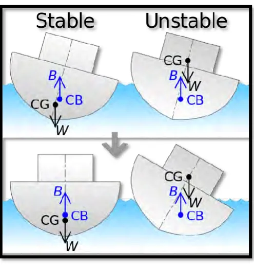
1.1 Stability
3 Figure 1.1: Stable and Unstable
1.2 Problem Statement
4 1.3 Objective
The objective of this project are:
1. To perform the buoyancy analysis on the 12 meter double hull boat. 2. To improve the buoyancy and stability of 12 meter double hull boat due to
the hull design using virtual simulation wind tunnel
1.4 Scope
5
CHAPTER 2
LITERATURE RIVIEW
2.0 Introduction
Literature is a process to review and explore to help process the introduction of new techniques for the design and analyse the shape of the hull. Through this process, all service information and detailed background studies related matters will be published. Each service information published will be understood by the authors to get a little overview and guidelines for the success of this analysis. Among the aspects involved in this research is the theory of buoyancy, stability, 3D scanners and simulations. All these aspects is essential for achieving the objectives of this project. 2.1 History Background
A boats are designed to float and water are used to perform work or as transport over water. Small boats usually used on inland waterways in areas such as lakes and rivers or coastal protected area. However the boat as the ship has been designed for use as a boat in the sea to catch a whale that has been designed for the operation of vessels in offshore environments. Terms of the navy, the boat is a small boat that can be carried on other ships.
6 boats that use wind energy, namely sailing boat movement is based on wind speed. The boats that are installed today are using motor power using petrol or diesel fuel. This is because this type of motor or engine are produce more power for a speed and more advance. Additionally, there is also a boat that can be used on land and on the water surface, known as a hovercraft.
7 Figure 2.1: Single Hull Boat Drawing
[image:23.595.117.504.416.626.2]Figure 2.2: Single Hull Existing Boat
8 Figure 2.4: Existing Catamaran Boat
2.2 History of Boat
According to Jean Vaucher (2014), History of the discovery of the world's oldest