Numerical Simulation of the Insert Chemistry of the Hollow
Cathode from the Deep Space 1 Ion Engine 30,000 Hrs Life
Test
IEPC-2007-113
Presented at the 30th International Electric Propulsion Conference, Florence, Italy September 17-20, 2007
M. Coletti* and A. Grubisic†
University of Southampton, Southampton, SO17 1BJ, United Kingdom
S.B. Gabriel ‡
University of Southampton, Southampton, SO17 1BJ, United Kingdom
Using a model for the insert chemistry developed by the authors and based on the knowledge of the BaO – CaO – Al2O3 ternary system the ELT discharge cathode insert from
the Deep Space 1 life test has been simulated. The computed data show a good agreement with the experimental one; the agreement increase with the imposition of boundary conditions closer to the experimental evidence. Tungsten deposition effect have been introduced into the model using experimental data and further improving the agreement between computed and measured data. The deposition trend found suggests the possibility of a link between barium depletion and tungsten deposition.
Nomenclature
A = Al2O3B = BaO
BC = boundary conditions
C = CaO
Da = diffusion coefficient
EDa = activation energy of the diffusion process IDS = inner diameter surface of the insert k = Boltzman constant
ODS = outer diameter surface of the insert OP = orifice plate surface of the insert q = electron charge
s.s. = solid solution
T = temperature
t = time
US = upstream surface of the insert
Δw = length of the insert covered by tungsten deposition starting from the OP
Π = insert porosity
I.
Introduction
OLLOW cathodes are one of the most important components in the field of electric propulsion. They are used as electron sources and neutralizers inside ion thrusters and Hall effect thrusters and in the future probably as stand alone microthrusters1-4 hence their lifetime is a key factor in all the application mentioned above.
One of the most important life limiting mechanism in hollow cathodes is depletion of low work function compounds from the insert. In a paper recently presented by the authors5 a model to predict barium depletion from a hollow cathode’s insert has been developed.
In this paper the model will be used to simulate barium depletion from the ELT discharge cathode and the numerical result will be compared to the experimental evidence collected during the Deep Space 1 Ion Engine 30,000 Hrs Life Test6.
II.
The chemical model
5Barium oxide diffusion and evaporation from the insert has been numerically modelled5 starting from the knowledge of the behavior of the ternary system BaO – CaO – Al2O37-9.
(a)
[image:2.595.121.490.257.593.2]dfg (b)
Figure 1. BaO-CaO-Al2O3 ternary diagram. (a) the whole diagram at 1250 °C, (b) particular of the diagram
Each point of the diagram in Fig. 1 (a) represents a state of the system where the concentration of A, B and C are inversely proportional to the distance of the point from each corner. Each area in the diagram represents a different state of the system hence which compounds are present.
Table 1 Compounds present in each area of the ternary diagram. The up lined formulas refers to a well define composition of the corresponding solid solution
Area N° Compounds Area N° Compounds
1 B3As.s. andB4A s.s. 8 B, C and B4As.s.
2 B3A s.s., B4A s.s. and B3CA 9 C andB4As.s. 3 B3A s.s. and B3CA s.s. 10 C, B4As.s. and B3CAs.s.
4 C, B3As.s. and B3CA s.s. 11 C and B3CA s.s
5 B4A s.s. and B8A s.s. 12 C, B3A and BA
6 B and B8A s.s. 13 C, BA and C3A
7 B,B4A s.s. and B8As.s. 14 AB, C3A and CA
From the knowledge of the compounds present it is possible to calculate the evaporation rate of barium oxide from the insert surface6,9,10. This evaporation creates a barium oxide concentration gradient generating a BaO motion from the insert core to the insert surface.
The motion of barium oxide from the interior part of the insert to the surface is the result of various processes: Knudsen flow of gaseous Ba and BaO through the pores, solid diffusion of BaO inside the BaO-CaO-Al2O3 impregnate, solid diffusion of BaO inside tungsten and surface diffusion of BaO along the pores surfaces.
These processes, being too complicated to be modelled separately, were represented globally with a single diffusion coefficient reducing the BaO depletion problem to a diffusion problem where the evaporation rate represents one of the boundary conditions.
The diffusion coefficient trend with temperature and insert porosities has been derived by comparison with experimental data11. The diffusion coefficient formula is reported below
eV E
s m c
s m b
e c b D
Da
kT Da qE
a
5 . 3
/ 01653 . 0
/ 1165 . 0
) (
2 2
= − =
= + Π
= −
(1)
III.
Numerical analysis
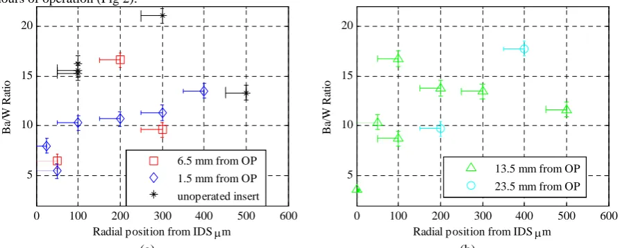
In Ref. 6 by means of EDX scanning the Ba/W ratio has been measured in various point of the insert after 30372 hours of operation (Fig 2).
0 100 200 300 400 500 600
5 10 15 20
Radial position from IDS μm
Ba
/W
Ra
ti
o
6.5 mm from OP 1.5 mm from OP unoperated insert
0 100 200 300 400 500 600
5 10 15 20
Radial position from IDS μm
Ba
/W
Ra
ti
o
[image:3.595.74.521.516.695.2]The barium-over-tungsten ratio has been also measured before the beginning of the test as shown by the black points in Fig 2. Looking at these data two hypotheses relative to the initial barium content in the insert have been made.
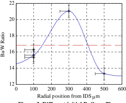
The first hypothesis is that at the beginning of the test the insert is completely filled with the impregnate, hence the initial BaO profile is flat (dashed line in Fig. 3) with a value that is the average of the measured values.
The second hypothesis is that due to the impregnation process the BaO profile is not flat; in this case its trend has been derived interpolating the measurements (solid line in Fig. 3).
The two profiles are represented below
0 100 200 300 400 500 600
12 14 16 18 20 22
Radial position from IDS μm
Ba
/W
Ra
ti
[image:4.595.189.395.202.369.2]o
Figure 3. Different initial BaO profile.
During the destructive test of the ELT cathode6 barium oxide deposits were found on the internal surface of the cathode tube and on the external surface of the insert showing how BaO evaporation occurs also from the outer diameter surface.
The insert chemistry has been simulated using the temperature profiles given in Ref 12 and with both the flat and the interpolated initial BaO profile.
Evaporation has been assumed to occur always from the inner diameter and from the upstream surface while different simulation have been done regarding the conditions of the outer diameter and orifice plate surface.
[image:4.595.90.505.500.629.2]The complete set of boundary conditions used is reported in Table 2 where with “open” we indicate a surface where evaporation occurs and with “closed” a surface where it does not.
Table 2. Different set of boundary conditions
Boundary Conditions set 1
Boundary Conditions set 2
Boundary Conditions set 3
Boundary Conditions set 4 Flat BaO
profile
IDS = open US = open ODS = closed
OP = closed
IDS = open US = open ODS = open OP = closed
IDS = open US = open ODS = closed
OP = open
IDS = open US = open ODS = open
OP = open Interpolated
BaO profile
IDS = open US = open ODS = closed
OP = closed
IDS = open US = open ODS = open OP = closed
IDS = open US = open ODS = closed
OP = open
IDS = open US = open ODS = open
0 100 200 300 400 500 600 5
10 15 20
Radial position from IDS μm
Ba
/W
Ra
ti
o
6.5 mm from OP 1.5 mm from OP
(a)
0 100 200 300 400 500 600
5 10 15 20
Radial position from IDS μm
Ba
/W
Ra
ti
o
13.5 mm from OP 23.5 mm from OP
(b)
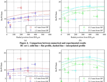
Figure 4. Comparison between numerical and experimental results BC set 1. solid line = flat profile, dashed line = interpolated profile
0 100 200 300 400 500 600
5 10 15 20
Radial position from IDS μm
Ba
/W
Ra
ti
o
6.5 mm from OP 1.5 mm from OP
(a)
0 100 200 300 400 500 600
5 10 15 20
Radial position from IDS μm
Ba
/W
Ra
ti
o
13.5 mm from OP 23.5 mm from OP
(b)
Figure 5. Comparison between numerical and experimental results BC set 2. solid line = flat profile, dashed line = interpolated profile
The best results were obtained with BC set 1 and 2 where the orifice plate surface is “closed”. Comparing Fig. 4 and 5 it can be seen how imposing that the external surface of the insert is “open” improve the results accuracy, as could be expected from the experimental evidence6.
Looking at Fig. 5 (b) and particularly to the data relative to 13.5 mm from the OP we can see how the interpolated profile gives better results than the flat one producing data that are much closer to the trend of the experimental point.
The data presented in Fig. 5 (a) show a poor agreement with the experimental points. In particular the predicted barium content is much lower than the measured one.
[image:5.595.78.522.106.275.2] [image:5.595.73.524.112.457.2]Figure 6. Tungsten deposition thickness along the insert13
An attempt has been done to include the tungsten deposition inside the model: to do so some hypotheses must be developed.
The first one is relative to the tungsten deposition trend on the IDS. Using the data computed before with the interpolated profile and BC set 2 the time evolution of the barium oxide content inside the insert at 1.5 mm from the OP has been analyzed. It can be noted that between 3000 and 5000 hours of operation the computed profile is quite close to the measured one after ca 31000 hours.
0 100 200 300 400 500 600
2 4 6 8 10 12 14 16
Radial position from IDS μm
Ba
/W
R
at
io
1.5 mm from OP 2000 hours 3000 hours 4000 hours 5000 hours
Figure 7. Ba/W ratio trend with time at 1.5 mm from the OP
It can be then assumed that during this time tungsten deposition has reached this point of the insert occluding the pores and consequently stopping BaO evaporation from this site of the insert.
Hence assuming that tungsten deposition starts from the downstream end of the insert, that at 4000 hours it has reached 1.5 mm from the orifice plate and that at 30352 hours it covers 3.5 mm from the OP the deposition trend is
42 . 0 2
10 6783 .
4 t
w= ⋅ −
Δ (2)
Where ΔW is the length in millimetres covered by tungsten starting from the orifice plate and t is the time in hours.
Noting that the barium depletion depth has been found to scale as the square root of time11, the trend in Eq. 2, (also if derived from numerical data), is quite interesting because it shows a possible relation between barium depletion from the insert and tungsten deposition.
The second hypothesis is relative to BaO deposition on the cathode tube. The barium oxide evaporated from the external surface of the insert creates deposits on the cathode tube as observed in Ref 6. If these deposits are big
Surf
ace Prof
il
e,
mm
0.05
0.00
-0.05
-0.1
-0.15
0 5 10 15 20 25 Axial position from the upstream surface, mm
Unoperated insert
[image:6.595.123.475.110.271.2]enough to fill completely the gap between the insert and the cathode tube they will occlude the insert pores preventing BaO evaporation.
Several numerical simulations have been run using the deposition trend in Eq. 2 and assuming different gap size between the insert and the cathode tube.
The gap sizes used are 25, 50, 75 and 100 μm. The best results were obtained with 75 and 100 μm.
0 100 200 300 400 500 600
5 10 15 20
Radial position from IDS μm
Ba
/W
Ra
ti
o
6.5 mm from OP 1.5 mm from OP
(a)
0 100 200 300 400 500 600
5 10 15 20
Radial position from IDS μm
Ba
/W
Ra
ti
o
13.5 mm from OP 23.5 mm from OP
(b)
Figure 8. Comparison between numerical and experimental results IDS deposition Eq. 2, ODS – cathode tube gap = 75 μm
0 100 200 300 400 500 600
5 10 15 20
Radial position from IDS μm
Ba
/W
Ra
ti
o
6.5 mm from OP 1.5 mm from OP
(a)
0 100 200 300 400 500 600
5 10 15 20
Radial position from IDS μm
Ba
/W
Ra
ti
o
13.5 mm from OP 23.5 mm from OP
(b)
Figure 9. Comparison between numerical and experimental results IDS deposition Eq. 2, ODS – cathode tube gap = 100 μm
The numerical results relative to 1.5 mm in Fig 8, 9 show a flat profile with a value close to the average of the measured values. The fact that the computed profile does not remain “frozen” as the one after 4000 hrs can be explained noting that in this point of the insert the diffusion motion (that is fast due to the high local value of the temperature, and hence of the diffusion coefficient) tends to move barium oxide upstream where it can evaporate and to smoothen the profile producing the flat profile computed.
[image:7.595.71.522.161.579.2] [image:7.595.76.519.173.348.2]Looking at the data relative to 13.5 and 23.5 mm from the OP we can note that these are not influenced by the introduction of deposition effect hence showing the same good agreement with the experimental data shown in Fig 2 by the data relative to the interpolated profile and BC set 2.
IV.
Conclusions and future work
The insert chemistry of the ELT discharge cathode from the Deep Space 1 Ion Engine 30,000 Hours Life Test has been simulated using as input data the initial barium oxide content and the insert temperatures. The computed data show a good agreement with the experiments improving the agreement when the imposed boundary conditions are closer to the real functioning of the insert.
Tungsten deposition effects on the IDS and barium oxide deposition on the cathode tube were added to the model starting from the experimental measurement. This improves the model prediction accuracy producing results that are in qualitative and quantitative agreement with the measurements except the data relative to 1.5 mm from the OP where the computed results give a flat profile with a value close to the average value of the measured data.
The tungsten deposition length is found to scale with a power of the time. This trend is quite close to the trend followed by barium depletion depth hence showing the possibility of a link between these two phenomena.
Future work will consist in the development of a low work function model deposition to be added to the chemical model that will be hopefully presented at the 46th AIAA Aerospace Sciences Meeting and Exhibit in Reno.
References
1
Gessini P., M. Coletti, N. Bevan, R. I. Marques, G. Michalareas, S.B. Gabriel, “Solar Electric Propulsion for Lunar
Transfer”, 1st Hellenic European Student Space Science and Technology Symposium, October 2006
2
M. Coletti, A. Grubisic, N. Wallace, “European Student Moon Orbiter Solar Electric Propulsion Subsystem Architecture.
An All – Electric Spacecraft”, IEPC-2007-111, 30th Electric International Propulsion Conference, Florence, Italy, September
2007.
3
P. Gessini, M. Coletti, A. Grubisic, and S. Gabriel, N. Wallace, D. Fearn, ”Hollow Cathode Thruster for All- Electric
Spacecraft”, AIAA-2007-5195, 43rd AIAA/ASME/SAE/ASEE Joint Propulsion Conference & Exhibit, Cincinnati, Ohio, USA,
July 2007.
4
angelo jpc
5
M. Coletti, S.B. Gabriel, “A Chemical Model for Barium Oxide Depletion from Hollow Cathode’s Insert”, AIAA-2007-5193, 43rd AIAA/ASME/SAE/ASEE Joint Propulsion Conference & Exhibit, Cincinnati, Ohio, USA, July 2007.
6
A. Sengupta, “Destructive Physical Analysis of Hollow Cathodes from the Deep Space 1 Flight Spare Ion Engine 30,000 Hr Life Test”, IEPC-2005-026, Princeton, November 2005
7
Appendino P., “Ricerche sul Sistema Ternario Calce-Ossido di Bario-Allumina”, Ceramurgia, 1972, pp. 103-106.
8
Lipeles R.A., Kan H.K.A, “Chemical Stability of Barium Calcium Aluminate Dispenser Cathode Impregnants”, Application of Surface Science 16, 1983, pp. 189-206
9 Wolten G.M., “An Appraisal of the Ternary System BaO-CaO-Al
2O3”, SD-TR-80-67, Space Division, Air Force System
Command, Los Angeles, October 1980
10
T.N. Resulhina, V.A. Levitskii, M.Ya. Frenkel, Izvestiya Akademii Nauk SSSR, Neorgan. Mater. 2, 1966, pp. 325-331.
11
Roquais J.M, Poret F., le Doze R., Ricaud J.L., Monterrin A., Steinbrunn A., “Barium Depletion Study on Impregnated Cathodes and Lifetime Prediction”, Applied Surface Science 215, 2003, pp. 5-17.
12
J. Polk, A. Grubisic, N. Taheri, D. Goebel, R. Downey, S. Hornbeck, “Emitter Temperature Distributions in the NSTAR
Discharge Hollow Cathode”, AIAA-2005-4398
13