A STUDY OF DIMENSIONAL LIMITATIONS
IN LOW PRESSURE DIE CASTING
AUTHOR: David Farnsworth
B. App. Sci.(R.M.I.T.)
Thesis submitted as a requirement for the completion of a
Masters of Engineering Science Degree
University of Tasmania.
Cc4,4
EARNS
tio OR TH
AUTHORITY OF ACCESS FOR THESIS
This thesis is not to be made available for loan or copying until the permission of
Comalco limited has been sought. Following that the Thesis may be made available
for loan and limited copying in accordance with the Copyright Act 1968.
crcols`^ d
Dated:
Signed:
DECLARATION
This Thesis contains no material which has been previously accepted for a degree or
diploma by the University or any other institution, except by way of background
information and has been duly acknowledged in the Thesis. To the best of the authors
knowledge and belief no material has been previously published or written by any
ACKNOWLEDGEMENTS
This Thesis is in collaboration with Southern Aluminium and the University of
Tasmania. In particular Dr. Vishy ICarri from the University of Tasmania and David
Sadler from Southern Aluminium Pty Ltd. I would like to give the highest possible
praise to these two gentleman for their encouragement and support. In particular Dr.
Vishi Karri whose constant guidance, support and much needed enthusiasm provided
much of the motivation to keep work progressing. Thanks to David Sadler and his
support both financial and moral, and the time required off my normal job. Special
thanks go to my colleagues who provided much needed technical support/input,
people such as Tony Hewitt, Tony Curtayne, Mark Kerrison and Gerd Siebert, who
all contributed technically to the thesis. I would like to thank all personal at Southern
Aluminium, since during the course of this thesis Southern Aluminium went through
the process of selling the business, not selling the business, and eventually closure.
Finally special thanks go to my wife and family who put up with my modes and time
in
ABSTRACT
This project is a study of low- pressure die casting process in Southern Aluminium
Pty. Ltd., a subsidiary of Comalco in Tasmania. The first major stage in the wheel
manufacturing process is casting. Wheels for automobile companies such as Nissan,
Ford and Mazda are cast using a low-pressure die casting process. A casting cycle
involves filling of the dies with molten aluminium solidifying the aluminium in the
dies, ejecting the solidified castings from the dies, quenching the castings to a
temperature close to room temperature and delivering the castings to the operator for
further processing. When running at full capacity, each casting machine is capable of
producing two castings simultaneously every six minutes. Each metal transfer into
the caster crucible yields enough volume of metal for the production of
approximately sixty wheels. The operator that initiates the casting cycle is
responsible for some further wheel processing operations. These operations include
the stamping of each cast wheel with a melt number stamp, manually removing any
visible marks from the front face of each wheel and removing excess aluminium
from the top and bottom rim of each wheel and finally, checking the castings for
distortion using a distortion gauge.
Each time the caster crucible is filled, an alloy sample is taken from the crucible and
examined spectrographically to determine alloy composition. The alloy composition
is recorded and the melt number is changed. The melt number of each cast wheel can
then be related to an exact alloy composition. A distortion gauge placed on the front
face of the wheel will inform the operator of the wheel distortion. A wheel that it
badly distorted, greater than plus or minus half a millimeter out of plane is rejected.
Further there is limitations on the minimum thickness that can be cast on these
wheels. The conditions to achieve the minimum thickness in effective casting have
been established in industry over a series of investigations. This project highlights
the conditions necessary to maintain minimum thickness in wheel castings, produced
by low-pressure die casting, by taking into consideration various process variables.
The stress analysis and solidification rates have been studied as a part of this
investigation using finite element and finite difference methods. The experimental
investigation in achieving minimum effective casting thickness complements the
iv
CONTENTS
Declaration
Acknowledgments
ii
Abstract
iii
Chapter One: Introduction 1
Chapter Two: Literature Survey 17
2.1 Patterns and Moulds 18
2.2 Melting and Metal 24
2.3 Defects in Casting 27
2.4 Other Casting Processes 30
2.5 Casting Processes Specific to Wheels 36
2.6 Concluding Remarks 45
Chapter Three: Finite Element Modelling 46
3.1 Finite Element Methods 49
3.2 Solution Using PATRAN 56
3.3 Use of FEA (Stress Analysis at Southern Aluminium) 62
3.4 The use of MAGMA solidification 68
3.5 Concluding Remarks 78
Chapter Four: Flexible Manufacturing Casting Cell 80
4.1 The Operation Layout 91
4.2 The Low Pressure Fill 94
4.3 The Die Operation 96
4.4 Concluding Remarks 97
Chapter Five: Qualitative and Quantitative Verification of Casting Dimensions 99
5.1 Ability to Manufacture and Pass Stress Requirements 99
5.2 Concluding Remarks 108
Chapter Six: Final Concluding Remarks and Future Work 109
6.1 Proposed Future Work 112
CHAPTER 1
INTRODUCTION
Our current lifestyle and expectations is a result of the industrialised age, critical to this is manufacturing. Manufacturing is on of the key components to the maintenance and improvements to our lifestyle and expectations. This lifestyle is only possible because of advances in mankind's ability to produce useful products on an economic scale. Technologies enable the production of components to stringent controls; critical controls are function and costs. The future of manufacturing lies in the ability to meet these criteria at higher and higher levels. This is the basis of mans economic advancement. The advances in industrialised countries such as Australia can only occur if we provide support to the process of improving our technologies and as a result our lifestyle and economic security. This is a fundamental of capitalist societies until this type of society no longer remains predominant the pressure explained above will remain
Manufacturing is the basis of industrialised societies. The process of improved standard of living drives the process of improvement. A person's expectation (or standard of living) changes with time. In a dynamic economic society this expectation will continually rise. Examples of this are boundless, but in the automotive environment the pace of change is huge. 40 years ago oil filters were optional, 30 years ago heater were optional, 20 years ago automatics were the least common option, while10 years ago air bags where uncommon. Today a majority of the options of a few years ago are now standard. Production as a part of Manufacturing involves the process of converting raw materials into useful products.
has no increase in value. One approach to the optimisation of manufacturing can be referred to as the minimisation of non-value added activities. Manufacturing changes the form of materials, using various processing techniques, to create useful products. The changes to material therefore produce a useful product of a higher value than prior to the beginning of the process. Raw materials needed for the production of any item has a value in its prime form. This is why manufacturing occurs, to increase value and hence produce an economic advantage.
If the enterprise adds value at a lower cost than the value it receives for its products it makes a profit. Profit is the amount of money resulting when revenues exceed costs, costs includes items such as depreciation, energy costs, and cost of raw materials, labour costs etc. Successful organisations will have increasing value-added activities and hence higher profits. It is the profit that allows the payment of dividends to owners and shareholders, the purchase of new equipment and plants and the payment of taxes.
A manufacturing system coordinates elements of input, process and output. Input in a manufacturing system includes consumer/customer demand, material, money, energy, human resources and education, whilst process includes design, production and management. A combination of input and process in a manufacturing system result in output of consumer goods, capital goods, satisfaction and quality and cost effectiveness.
It should be noted that advances in manufacturing are often linked with advances in automation. Modern Australian manufacturing can and in some circumstances does compete well in the world but due to our relatively high labour rates Australia must compete from a level of higher technology and methodology. Automation can for example replace tedious competitive jobs or jobs that have adverse environments. The extra advantages of using automation in such roles is reduction in a faulty product due to the elimination of human errors and the consistent quality and rate of production regardless of whether it is Friday afternoon or Monday morning.
Automation is only one part of the manufacturing process operation hence other methods and processes must be considered. The common methodology used for all these processes include common processes such as Just in Time (JIT), Manufacturing requirements planning (MRP) and fail safe mechanisms. The results of these activities are to provide assistance with optimisation of all facets of manufacturing from inventory control to machine line layout and sequencing. These systems become a manufacturing philosophy with the intent of productivity optimisation by maximising efficiency of product flow and minimising inventory.
In all these optimisation systems there is a common goal of maximising productivity
• .
within all areas of the manufacturing environment with each area contributing in a
cumulative manner to the operations overall productivity. Flexible manufacturing systems can contribute to productivity improvements in actual manufacturing operations. Materials requirement planning (MRP), on the other hand, provides assistance with efficiency improvements in materials requisitioning and inventory levels. Another very important factor in improving productivity in manufacturing operations is to be able to understand and optimise the product flow through the plant. The product flow analysis is called PFA.
driving force for improving technologies in modern manufacturing systems. Improvements in productivity can be described as lowering the Non Value added activities. This also extends to changes in these same operating cycles and processes to ensure a better quality product at the end of production. Ultimately, the objective of productivity improvements is to result in the production of more items with higher quality at a lower cost. This is the aim that modern manufacturing organisations endeavour to achieve. As a result of successful productivity improvements the output from manufacturing systems such as quality and cost effectiveness are achieved.
Planning of manufacturing activities is necessary for a manufacturing operation to be efficient. Process planning determines the required operations and necessary facilities to manufacture a part or product. It is concerned with selecting methods of production, tooling, fixtures and machinery, sequencing of operations and assembly. Two aspects of process planning are specification of a suitable production schedule and determining production speeds for minimum cost and maximum production rate. Process planning determines product flow within a manufacturing system. Product flow is the flow of product throughout the manufacturing system from initial to finished product. Factors that influence product flow are the sequencing of necessary production operations to give the most efficient process, plant layout and the ordering of operations such that necessary tasks are completed in the correct order of processing. Product flow analysis assists in achieving the most economical use of floor space and is used to assess sequencing of operations to determine the optimum arrangement of equipment. In its broadest sense, product flow is used to analyse products flowing through a plant and assess the most appropriate paths and sequencing of events. The study of product flow within a manufacturing environment involves the optimisation of a problem by analysis of all the options and alternatives within the problem. It is very important that the focus of the problem remains the desire for an increase in productivity. There is a need for understanding product flow and process planning as a part of controlling and optimising overall production time and production rate. Without efficient product flow productivity cannot be optimum. Improvements that arise from product flow analysis contribute to the productivity improvements of the operation.
achieved with various devices, sensors, actuators techniques and equipment that are capable of observing the manufacturing process, making decisions concerning the changes that should be made in the process and controlling all aspects of the • processing operations. The major goals of automation in manufacturing facilities are to integrate various operations to improve productivity, increase product quality and uniformity, minimise cycle times and effort, reduce labour costs, reduce possibilities of human error and raise the level of safety for personnel. The basis areas of activity in manufacturing plants that are subject to automation include manufacturing processes such as machining, forging and grinding; material handling during various stages of completion; inspection of part for quality, dimensional accuracy and surface finish; assembly of parts and final product; and packaging.
Material handling and material movement is a significant aspect of automation in manufacturing plants. Most manufacturing systems require the moving of materials and parts between processes in order to produce a finished product. Manufacturing systems with individual operations, require a large amount of material handling for the transfer of parts between processes. Material handling between processes adds cost but not value to a product and for this reason should be kept as minimal as possible.
Flow of materials and components throughout the manufacturing cycle is greatly effected by plant layout. The arrangement of production machinery and material handling equipment should be orderly and efficient. Various factors need to be considered when choosing a material handling method for a particular manufacturing operation. These include shape, weight and characteristic of parts; types of movement and distances involved the position and orientation of parts during movement to their final destination. Other factors include condition of the path along which parts are to be transported; degree of automation and control desired and integration with other
systems and equipment; operator skill required and economic condition.
product needs, for commercial reasons to exceed those limitations, clear directions and possibilities can be explored early in the design process.
The variables this thesis will look at are primarily weight related and hence will focus on dimensional minimums. Southern Aluminium is a wheel producer in the world market looking for competitive edge. One of those advantages is Southern Aluminium's ability to produce product at as light as weight as possible
It is generally excepted that heavier product is easier to manufacture. This sets up a potential conflict of interest between production requirements and customer requirements. It should be clear to all manufactures that two prime criteria must be reached these are:
1. The proposed product must fulfil the customer general requirements these include in order of priority safety, price, and weight.
2. Southern Aluminium must be able to manufacture the product in a profitable and effective manner.
The intent of this thesis is to clearly or provide a methodology to define the manufacturing possibilities in order that this can be used to smoothly inform customers as to the possibilities of their styling requirement.
There have been tremendous improvements in vehicle performance/function over recent years. Performance improvements relate primarily to features and fuel economy. Consumers of automobiles are unlikely to change their expectation for creature comforts, eg air conditioners, power steering, NVH (Noise Vibration Harshness), air bags etc. Due to these continuing pressures the emphasis will be losing weight without losing function. Every extra gram of weight adds significantly to the vehicles fuel usage over the life of the vehicle.
issues that effects the profitability of the product must be treated with the upmost seriousness. Product must (to be profitable) brought into production as easily as possible.
This thesis is intended to be in part used in the design process to minimise the chance of any miscalculations moving through the design stage which may result a major operating flaw in the production process.
Southern Aluminium Pty Ltd is a manufacturer of automobile wheels and is a wholly owned subsidiary of Comalco Aluminium Ltd. Comalco, a 67% subsidiary of Rio Tinto (formally CRA), has operations that produce a high percentage of Australia's bauxite and a large percentage of Australia's primary aluminium. Include in its operations are 3 primary aluminium smelters one (the groups oldest) exist adjacent to Southern Aluminium in the North of Tasmania near the deep-sea port of Bell Bay. The other two smelters are located in New Zealand and Queensland. The combined production of all 3 smelter is near 700,000 tonnes/annum and dependant on commercial forces this production output can be met.
Southern Aluminium was established in 1989 having to meet production in excess of 50,000 wheels per month for the world automobile industry. Southern Aluminium was established when Comalco had a deliberate policy of supporting value-added activities outside of its smelter operations. Comalco has since changed its philosophy on value adding outside of the smelter operations and as a consequence of this Southern Aluminium is now in the process of being sold.
Southern Aluminium customers include well-established automobile manufacturing companies such as Nissan, Mazda, Mitsubishi and Ford. Southern Aluminium produce a variety of wheel types and offer a complete package in design from initial renderings from the customer through, casting, machining and finishing of aluminium wheels. The company has developed a consistent theme of quality awareness throughout the plant and a philosophy of process control and quality assurance.
The properties aluminium alloy 601 possesses make it a most suitable material for all
stages of the automobile wheel manufacturing process, including casting, heat treating,
machining, and finishing with subsequent improvement in service life.
All wheels at Southern Aluminium are produced using commercial aluminium alloy
601. The constituents added to aluminium to produce alloy 601 are approximately by
weight 7% silicon, 0.3% magnesium, and 0.005% strontium, making the alloy
predominantly an aluminium-silicon-magnesium system. Aluminium alloy 601 is used
as the work material at Southern Aluminium due to its consistent mechanical
properties and structural integrity in permanent mould castings, this material is also
specified by customers.
There is several Characteristics that make an aluminium wheel preferable to steels
wheels traditionally used, these advantages include:
1. Aluminium wheels have higher cosmetic value than the alternate steel wheels.
2. Alloy wheels can in some circumstance be lighter than their steel counterparts,
which has certain advantages for handling on vehicles by lowering the unsprung
weight
3. Alloy wheels are produced in a lathe. Rolling the rim produces steel wheels. The
later process has poor capability in producing good runout results. Alloy rims are
produced using a lathe. Subsequently an alloy wheel has excellent runout results.
4. Aluminium has a higher thermal transfer coefficient. This can result in lower hub
temperatures, with subsequently better brake and tyre performance.
In combination of the above effects the use of aluminium alloy wheels can improve
tyre safety and wear with improved braking characteristics.
The manufacturing process employed at Southern Aluminium is now briefly
Heat treatment of Tramped to customers Machining lines
OP 1,2,3 & 4
Slim, added
Other alloying demets and degassimg
Attlee& test wheels fa leaks
Vertical a* hertz:real Painting Stud inserticn
Rulout and
X-ray of wheel
Packityjng and Ccntainerizaticn Is Internal detect
acceptadd
[image:17.568.100.432.46.530.2]Shot blast
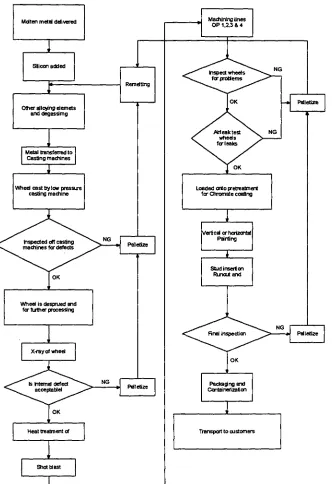
Figure 1. The process flow chart as a representation of the Southern Aluminium
manufacturing process
Molten aluminium is delivered to Southern Aluminium, as it is needed, from the
nearby aluminium smelting plant. It is delivered in large crucibles that are able to
maintain the molten temperature during transportation. The molten aluminium is kept
in large holding furnaces where it is alloyed up with the main alloying component of
601, that is silicon. The material is then transferred into smaller mobile crucibles,
known as 'transfer crucibles' where the final alloying and metal cleaning processes
process then removes the major contaminating elements of hydrogen and metallic oxides.
Following on from the initial molten metal preparation and filling of the casting machine crucibles there are four major operations that contribute to the manufacturing of a wheel at the plant. These are casting, heat treatment, machining and finishing. Each of these four major operations involves a series of smaller individual operations. Figure 1 shows product flow, involving these four major stages of production, throughout the plant.
It can be seen from the product flow chart that the first major stage in the wheel manufacturing process is casting. Wheels are cast using a low-pressure die casting process, the principles of which are discussed later. The plant has eight low-pressure die casting machines in total, which are grouped together as four pairs. A single operator is responsible for the operation of one casting machine, each casting machine has 2 cavities or moulds. A human operator pressing the appropriate buttons on the casting machine control panel initiates each casting cycle. A casting cycle involves filling of the dies with molten aluminium, solidifying the aluminium in the dies, ejecting the solidified castings from the dies, quenching the castings to a temperature close to room temperature and delivering the castings to the operator for further processing. When running at full capacity, each casting machine is capable of producing two castings simultaneously every six minutes. Each metal transfer into the caster crucible yields enough volume of metal for the production of approximately sixty wheels. The operator that initiates the casting cycle is responsible for some further wheel processing operations. These operations include the stamping of each cast wheel with a melt number stamp, manually removing any visible marks from the front face of each wheel, manually removing excess aluminium from the top and bottom rim of each wheel and finally, checking the castings for distortion using a distortion gauge. A melt number stamp is essential on each cast wheel so that the alloy content of the wheel can be identified if needed.
distorted, greater than plus or minus half a millimetre out of plane, is rejected immediately. Molten metal is fed at low pressure from the caster crucible through a tube into the centre of the bottom die and continues to be fed into the die until sufficient metal has entered to fill the cavity. A fine steel wire mesh is placed into the centre of the bottom core of each die prior to initiating the casting cycle to prevent impurities entering the casting. Any impurities in the molten aluminium present in the caster crucible become caught in the wire mesh during the casting cycle and solidify. This solidified form stays attached to the casting as it is removed from the die. This solidified form, containing impurities and the fine steel wire mesh, is known as a `sprue' and is removed from each casting using an automated drilling operation. In this operation, a wheel is fed automatically from the casting machine, via a conveyor, into the drilling machine. Inside the drilling machine the wheel is clamped automatically, drilled to remove its sprue and machined across the back of the rim to remove excess flashing.
The wheel is then automatically delivered to another conveyor where it travels to the x-ray machine. At the x-ray machine, the wheel undergoes x-raying to determine porosity content and other possible defects. An operator watches the wheel as it is x-rayed and determines at the end of the x-raying cycle whether or not the wheel must be rejected by comparing the wheel porosity content with a sample showing the maximum porosity size and scattering allowed. X-raying is the final operation in the casting section of the plant. Material handling between processes is highly automated in the casting section of the plant. The high degree of automated wheel handling also means that there is much faster and more consistent transfer of wheels between subsequent processes than there could be without automated material handling.
The strength and hardness properties of a wheel directly after casting are not sufficient to meet customer specifications. Wheel properties in the 'as-case condition do not meet the customer requirements
Following the quench is a shorter period of heating at temperature approximating 150°C. This process is referred to as artificial aging. The specific heat treatment method adopted at Southern Aluminium is designated below.
Table 1: Heat treatment process employed at SAPL
Process
Time
Temperature
Solution treatment
4.5 — 7.5 hrs 540 - 5300Water Quench
As fast as practical 800Age
3 — 5 hrs 140°The heat treatment process is a long process and constitutes the longest value added process in the plant. For this reason Southern places a lot of emphasis is place on the length of this process2.
An operation used to give each wheel face a predetermined surface texture is called 'shot blasting'. Which follows immediately after heat treatment. During this operation wheels are struck repeatedly at high speed and force with small steel or balls, known as shot, of less than one millimetre diameter. An impression is left on the front face of the wheel after each strike of the shot. This results in a desired surface finish on the wheel that improves its visual appearance and aids in paint adhesion during painting operations carried out later in the processing cycle. Excess aluminium is removed from the wheel as a desirable secondary action during this operation due to the high speed and force at which the shot strikes the wheel. Surface machining of the wheel follows directly from shot blasting. Machining of wheels is a necessary step in the wheel manufacturing process as an `as-case wheel is not of a satisfactory standard for commercial use.
each capable of performing these operations. Each machining line can be set-up to machine any one-wheel type at any given time. Each machining line is programmed for each wheel type produced at the plant. As there are five individual machining cells it is possible to carry out machining operations on five different wheel types at any one time. With this automated surface machining process, the only human intervention is the manual stacking of wheels at the end of the machine lines. To process a wheel through each of the machining operations mentioned earlier takes two to three minutes from start to finish. All machining operations are carried out automatically inside the machine and machined wheels are delivered to the operator at the end of the machine line, ready for further processing. The machining cells are the most advanced automated processing equipment in the plant and are an excellent example of how automation can save time, effort and money in a manufacturing system. Wheels delivered to the operator at the end of the machine lines are subject to a 'leak test' which involves immersing an air tight wheel completely underwater and viewing the water for escaping air bubbles from the wheel rim section. Air bubbles escaping from a wheel indicates a defect in the wheel rim and thus the wheel must be rejected. The air leak test is a vital component of the wheel manufacturing process as wheels must not be allowed to leave the plant if they fail this test. Most of the tyres used in conjunction with aluminium wheels are tubeless so thus a wheel with an air leak fitted to a vehicle can be detrimental to passenger safety.
The final stage of wheel processing is finishing. The primary operations that fall into the category of finishing are detergent washing, spray painting (also wet painting), powder coating and paint curing of wheels and inspection and packaging of wheels for storage and shipment. Detergent washing of the wheels is necessary to ensure that the wheel is completely free from contaminants before painting. Wheels are delivered to the detergent washing centre on vertical hangers, which support two wheels only. The vertical hangers are contained on a continuous chain that runs through the detergent washing, powder coating and paint curing sections of the plant. The operations of
the spray painting guns. Once spray painted, the wheels are returned to the vertical hangers from which they were taken. Wheels then continue through to the powder coating and paint curing operations. Powder coating is an operation that covers the surface of each wheel with a thin layer of paint in powder form. To harden the powder on the wheel it is necessary to subject the wheel to a paint curing operation. During paint curing, wheels travel through an oven set at nominally 190°C for approximately thirty minutes during which time the powder forms a hard, clear coating on the wheel. After paint curing the wheels are manually removed from the vertical hangers, stacked onto pallets and stored until required for final inspection. Some wheel types, depending on their shape, may require painting directly after shot blasting and prior to machining. Wheels that do require spray painting before machining are still powder coated and inspected after machining, as demonstrated on the product flow chart in Figure 1. Final inspection of the wheels involves an operator visually examining each wheel and deciding whether or not the wheel can be shipped depending on its condition. At final inspection, wheels may be rejected or sent for rework or reface if they are not of an acceptable standard to send to the customer. Some common problems that cause a wheel to be rejected or sent for rework or reface at final inspection include paint defects, discovery of defects not noticed earlier during processing or damage to the front face of the wheel.
Automation of processes and automated material handling plays a very important role in the manufacturing of wheels at Southern Aluminium. Transfer of wheels between substations in the casting, heat treatment and machining sections of the plant is carried out with automated material handling systems such as conveyors, sensors and mechanical grippers, thus leading to the need for very little human interaction.
the organisation. That is, for every step of successful processing that a wheel undergoes it will increase in value to the company until such time that it is ready for shipment. To reject a wheel after painting or machining is much more costly to the company than to reject a wheel at the casting stage. All reject wheels are remelted at the plant. Reworking and refacing of wheels are alternative operations to rejection for some wheels. These operations often involve re-machining or sanding the front face of a wheel to remove micro-porosity of minor defects. Reworking and refacing are again costly and undesirable operations but are sometimes necessary and are cheaper options to rejecting a wheel. Reworked and refaced wheels need only to undergo a few reprocessing operations before they are ready for shipment whereas a reject wheel must be melted and totally reprocessed. Southern Aluminium is a quality-accredited company that strives for quality but the production of some reject wheels is inevitable. To achieve one hundred percent quality in the manufacturing process and eliminate tasks not on the critical path of processing, such as reject, rework and reface, is an ultimate goal of every company in theory but is, however, unlikely to be achieved in practice. Continual improvement and reduction of rejects as a result of research and development is an ongoing task at Southern Aluminium.
To ensure product control a range of non-destructive and destructive testing. is maintained. Apart from essential quality control requirements stipulated by Southern Aluminium's customers, the company institutes a number of additional internal manufacturing process and quality control procedures to minimise work-in-progress scrap throughout the manufacturing cycle. It is useful here to introduce the control points that are critical points to demonstrate the manufacturing process and the controls that are introduce to ensure the quality. It is worth noting the Southern works to Total Quality Management. This refers to the fact that all parts of the operation are responsible for quality. Southern does not have a quality control department but has a quality assurance group, which is essentially very small.
these gains to be shared with the customer. If flexible manufacturing is allowed to
flourish and improve itself this can result in a win/win position.
It is concerned with selecting methods of production, tooling, fixtures and machinery,
sequencing of operations and assembly. Two aspects of process planning are
specification of a suitable production schedule and determining production speeds for
minimum cost and maximum production rate. Process planning determines product
flow within a manufacturing system. Product flow is the flow of product throughout
the manufacturing system from initial to finished product. Factors that influence
product flow are the sequencing of necessary production operations to give the most
efficient process, plant layout and the ordering of operations such that necessary tasks
are completed in the correct order of processing. Product flow analysis assists in
achieving the most economical use of floor space and is used to assess sequencing of
operations to determine the optimum arrangement of equipment. In its broadest sense,
product flow is used to analyse products flowing through a plant and assess the most
appropriate paths and sequencing of events. The study of product flow within a
manufacturing environment involves the optimisation of a problem by analysis of all
the options and alternatives within the problem. It is very important that the focus of
the problem remains the desire for an increase in productivity. There is a need for
understanding product flow and process planning as a part of controlling and
optimising overall production time and production rate. Without efficient product flow
productivity cannot be optimum. Improvements that arise from product flow analysis
contribute to the productivity improvements of the operation.
As shown in figure 1 the first part of the process is casting. If this process is not
performed satisfactorily or performed incorrectly the potential for the error to be
multiplied through the process specifically in cost is enormous. This is why successful
introduction of product into the casting process is essential for a successful business.
The basis of this thesis is to provide a methodology for improved design involving
minimum effective thickness in casting and process development, which will enable
the most successful introduction of product into the business and hence give the
CHAPTER 2
LITERATURE SURVEY
Casting is one of the oldest manufacturing processes, and even today it is the first step in manufacturing most products 13,41. With number of process variables involved during this manufacturing process, casting can be difficult to 'get it right'. In the casting process, the material is first liquefied by properly heating it in a suitable furnace. Then, the liquid is poured into a previously prepared mould cavity where it is allowed to solidify. Subsequently, the product is taken out of the mould cavity, trimmed, and cleaned to shape. The liquid metal influences and is influenced by its environment, exchanging alloys, impurities, and gas. The surging and tumbling flow of the molten liquid can introduce bubbles that create imperfections in the final casting. There is a need to exercise control during the freezing and subsequent cooling stages to ensure less distortion. The solidified casting strives to contract whilst being resisted by the mould. The casting when not properly carried out can result in excessive internal stresses and strains that can lead to failure. In this chapter a brief review of aluminium alloy casting is carried out with a view to highlighting the effect of major process variables on the casting performance. A brief review of casting processes is carried out before the detailed study of the aluminium alloy casting.
It is clear from the definition of the process that a successful casting operation needs knowledge in the following areas:
I. Preparation of moulds and patterns (used to make the mould). 2. Melting and pouring of the liquefied meta
3. Solidification and further cooling to room temperature. 4. Defects and inspection.
There are various types of casting processes depending, among others, on the material, the type of patterns and moulds, and the pouring technique.
The suitability of the casting operation for a given material depends on:
1. The melting temperature of the job and the mould materials, 2. The solubility of and the chemical reaction between the job and the
mould materials,
3. The solubility of the atmosphere in the material at different temperatures to be encountered in the casting operation,
4. The thermal properties such as conductivity and coefficient of linear expansion of both the mould and job materials.
2.1 Pattern and Mould's
A pattern is the replica of the part to be cast and is used to prepare the mould cavity. Patterns are made of either wood or metal 141 . A mould is an assembly of two or more metal blocks, or bonded refractory particles (sand) consisting of a primary cavity. The mould cavity holds the liquid material and essentially acts as a negative of the desired product. The mould also contains secondary cavities for pouring and channelling the liquid material into the primary cavity and to act as a reservoir, if necessary.
A four-sided frame in which a sand mould is made is referred to as a flask. If the mould is made in more than one part, the top portion is called the cope and the bottom one is termed as the drag. For producing hollow sections, the entry of the liquid metal is prevented by having a core in the corresponding portion of the mould cavity. The projections on the pattern for locating the core in the mould are called core prints. There are diverse types of patterns and moulds depending on the material, the job, and the number of castings required.
2.1.1 Pattern Allowances
A pattern is always made somewhat larger than the final job to be produced. This excess in dimensions is referred to as the pattern allowance. There are two categories of pattern, namely, the shrinkage allowance and the machining allowance.
The shrinkage allowance is provided to take care of the contractions of a casting. The total contraction of a casting takes place in three stages, and consists of.
(i) The contraction of the liquid from the pouring temperature to the freezing temperature,
solid,
(iii) The contraction of the solid casting from the freezing temperature to room temperature.
It must be noted, however, that it only the last stage of the contraction which is taken care of by the shrinking allowance. Obviously, the amount of shrinkage allowance depends on the linear coefficient of thermal expansion al of the material. The higher the value of this coefficient, the more the value of shrinkage allowance.
Usually, a cast surface is too rough to be used in the same way as the surface of the final product. As a result, machining operations are required to produce the finished surface. The excess in the dimensions of the casting (and consequently in the dimensions of the pattern) over those of the final job to take care of the machining is called the machining allowance 151 . The total machining allowance also depends on the material and the overall dimension of the job, though not linearly as the shrinkage allowance.
There is another deviation from the original job dimensions and is intentionally provided in the pattern; this is called draft. It refers to a taper put on the surface parallel to the direction of withdrawal of the pattern from the mould cavity. A draft facilitates easy withdrawal of the pattern. The average value of the draft is between
1/2° and 7° [5'6' 7].
2.1.2 Types of Patterns.
The commonly-used patterns are classified as follows:
Loose pattern. It is made in one piece, usually from wood, and is used for castings numbering up to 100.
Gated pattern. This is simply one or more than one loose pattern with attached gates and runners and provides a channel through which the molten metal can flow from the pouring sprue to the mould cavity. This pattern is frequently set on a follow board conforming to the parting surface of the mould. The follow board helps in an easy removal of the pattern after the mould has been prepared.
4,,S cm (negative allowance) 1...a--45 em-4.4
14-S0 an-14
between the cope and the drag flasks by means of locating pins. For small castings, several patterns can be mounted on the same match plate.
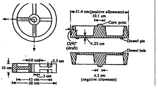
(iv) Cope and drag pattern. Here, the cope and drag halves of a split
pattern (Fig 2.1) are separately mounted on two match plates. Thus, the cope and the drag flasks are made separately and brought together (with accurate relative location) to produce the complete mould.
(v) Sweep pattern. Normally made of wood, it is used to generate surfaces
of revolution in large castings, and to prepare moulds out of a paste-like material. Here, 'sweep' refers to the section that rotates about an edge to yield circular sections.
(vi) Skeleton pattern. This consists of a simple wooden frame outlining the
shape of the casting. It is used to guide the moulder for hand-shaping the mould and for large castings having simple geometrical shapes.
[image:28.568.170.440.535.689.2]While designing a pattern, the parting line should be chosen so as to have the smallest portion of the pattern in the cope. As the moulding sand has greater strength in compression than in tension, the heaver sections of the pattern should be included in the drag. The possible defects due to loose sand in the mould are more frequent in the cope hald. For this reason, the most critical surface should also be included in the drag.
Figure 2.1 shows a typical split pattern (with allowances) for a cast iron wheel. The reader is advised to carefully note all the allowances, positive and negative.
2.1.3 Types of Moulds
Moulds can be classified on the basis of either the material, i.e. green sand mould, plastic mould, metal mould, or on the method of making them, e.g., shell mould and investment mould. Metal moulds are permanent in the sense that a large number of castings can be made from a single mould; on the other hand, moulds of refractory materials can be used only once. Generally, the green sand moulds are used; in what follows, we shall consider some of their important characteristics.
2.1.3.1 Green Sand Mould
The material for a green sand mould is a mixture of sand, clay, water and some organic additives, e.g. wood flour, dextrin, and sea coal. The percentage of these ingredients on weight basis is approximately 70-85% sand, 10-20% clay, 3-6% water, and 1-6% additives. This ratio may vary slightly depending on whether the casting is ferrous or nonferrous.
Sand is an inexpensive refractory material, but natural sand may not have all the desirable qualities of a moulding material. For example, it normally has higher clay content than desired. The sand used as a moulding material should have a specified clay, water, and additive content; in addition, it must have a specific grain size distribution. The importance of the grain size distribution would be clear from the discussion that follows.
Clay, together with water, acts as a bonding agent and imparts tensile and shear strength to the moulding sand. The organic additives burn out at high temperatures and make room for the moulding sand to expand, and thus save the mould from crumbling.
The success of a casting process depends greatly on the properties of the moulding sand. These include (i) strength, (ii) permeability, (iii) deformation, (iv) flowability, and (v) refractories. (Standard specimens and tests are recommended for an evaluation of these properties). Strength refers to the compressive strength and deformation indicates the change in length of a standard specimen at the point of failure. Permeability is expressed as the gas flow rate through the specimen under a specified pressure difference across it. Flowability refers to the ability of the sand to flow around and over the pattern when the mould is rammed. Refractoriness measures the ability of the sand to remain solid as a function of temperature. For a given sand-clay ratio, the nature of variation of these properties with water content is as shown in Fig. 2.2. It is obvious, both from strength and permeability considerations, that there is an optimum water content. At a low water content, dry clay powder, being finer than sand grains, fills up the void between the sand particles, and thus reduces
_,P Flowability
Permeability Deformation
Strength
4.
0 2 4 6 8 10 12
Per cent water content
the permeability. With higher water content, moist clay forms a coating over the sand particles keeping them further away, thus enhancing the permeability. Beyond the optimum water content, water itself fills up the void and reduces the permeability.
2.1.3.2. Preparation of Mould
Moulds are made by hand if the number of moulds to be prepared is small. If a large number of simple moulds are required, moulding machines are then used. In this section, we shall briefly discuss some important features of mould making; also, some typical moulding machines will be outlined.
To facilitate an easy removal of the pattern, a parting compound, e.g., nonwetting talc, is dusted on the pattern. Fine grain facing sand is used to obtain a good surface on the casting. Normally, a dead weight is placed on the cope flask to prevent the cope flask from floating due to hydrodynamic forces of the liquid metal. For a large mould, care should be taken to prevent the sand from falling off the cope flask when it is lifted to remove the pattern. This can be done by providing extra supports, called gaggers, within the cope flask. For a casting with re-entrant surfaces, e.g. a wheel with a groove at the rim, the mould can be made in three parts (Fig 2.3). The part between the cope and the drag is termed as the cheek. For an easy escape of the gases, vent holes are provided in the cope flask.
The moulding machines operate on one or a combination of the principles explained in Fig 2.3. In jolt ramming, the mould is lifted through a height of about 5cm and dropped 50-100 times at a rate of 200 times per minute. This causes somewhat uneven ramming, but is quite suitable for horizontal surfaces. On the other hand, squeezing is found satisfactory for shallow flasks. The sand slinging operation is also very fast and results in uniform ramming. This, however, incurs high initial cost.
Dead weight
0,
:14.
1
1
31111111111.1114 I I
I
" " " III I
I IN
•
0 [image:31.568.139.434.584.733.2]1.7•7■74767•74■747•7•74:"4■74 ■niva.W:41■■■'•■■•■■■
Figure 2.3: Principles of machine moulding operation
Cope
2.1.3.2 Permanaent moulds.
Permanent moulds are predominantly used for high productivity simple shaped castings [171' Molten metal is introduced into the mould under gravity or with low-pressure assist. Aluminium, magnesium, zinc, lead, copper-base alloys are the principal alloys cast.
The process works best in continuous operation so that the mould temperature can be maintained within a fixed operating range. Operating temperature of the mould is one of the most important factors in successful permanent mould casting [17] . Metal moulds are associated with the die-casting industry.
2.2 Meltime and metal
A proper care during melting is essential for a good, defect-free casting. The factors to be considered during melting include gases in metals, selection and control of
scrap, flux, furnace and temperature.
2.2.1 Pouring (Gating Design)
After melting, the metal is poured or injected into the mould cavity. We shall now discuss the difficulties faced in doing this and explain how these can be overcome by using an appropriate gating design. A good gating design ensures distribution of the metal in the mould cavity at a proper rate without excessive temperature loss, turbulence, and entrapping gases and slags.
If the liquid metal is poured very slowly, then the time taken to fill up the mould is rather long and the solidification may start even before the mould has been completely filled up. This can be avoided by using too much superheat, but then gas solubility may cause a problem. On the other hand, if the liquid metal impinges on the mould cavity with too high a velocity, the mould surface may be eroded. Thus, a compromise has to be made in arriving at an optimum velocity.
.-• •- ••
2
f
::•'7,7.-.T• • - --:::' - ... *.: 3
Ope to 1
atmosphere •M°uld n
Atmospheric pressure
Pouring basin
Mould
h
however, a short path for the liquid metal is selected to avoid a high pouring temperature. The gating design for a ceramic mould is quite different from that normally used for a permeable sand mould.
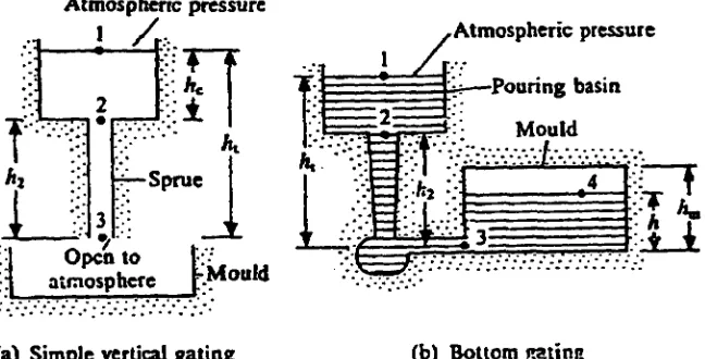
Broadly, gating designs can be classified into three categoeis, namely, (i) vertical gating, (ii) bottom gating, and (iii) horizontal gating. In vertical gating, the liquid metal is poured vertically to fill the mould with atmospheric pressure at the base. In bottom gating, on the other hand, the liquid metal is filled in the mould from bottom to top, thus avoiding the splashing and oxidation associated with vertical gating. Figure 2.4 shows a simple vertical gating and a bottom gating design. In the horizontal gating system, additional horizontal portions are introduced for better distribution of the liquid metal with minimum turbulence.
Simple calculations based on principles of fluid flow can lead to an estimate of the time taken to fill up a mould. We shall illustrate this for the two designs in Fig. 2.5. The integrated energy balance equation on the basis of per unit mass flow, more commonly known as Bernoulli's equation, will be used. For example, in Fig. 2.6a, it is assumed that the pressure at points 1 and 3 is equal (i.e. p1 = p3) and that level 1 is maintained constant. Thus, the velocity at station 1 (v1) is zero. Moreover, the frictional losses are neglected. Then, the energy balance equation between points 1 and 3 gives
Atmospheric pressure
[image:33.568.149.473.484.649.2](a) Simple vertical gating (b) Bottom gating
ght .v3 2 /2
or v3 =
where g is the acceleration due to gravity and v3 is the velocity of the liquid metal at
the gate, subsequently referred to as vg. So, the time taken to fill up the mould (tf) is
obtained as:
V tf = A v g 3
where Ag and V are the cross-sectional area of the gate and the volume of the mould,
respectively.
In Fig 2.4b, applying Bernoulli's equation between points 1 and 3, we get
‘,2
ght _ p3 ± • 3
Pm 2
where pm is the density of the liquid metal, p3 is the gauge pressure at station 3, and
ht is again assumed to be constant. Further, applying Bernoulli's equation between
points 3 and 4, with the assumptions that v4 is very small and all the kinetic energy
at station 3 is lost after the liquid metal enters the mould, we can write
P3 Pm =
From the last two equations, the velocity of the liquid metal at the gate we obtain is
vg = v3 = V2g(h„ — h)
The last equation gives the velocity of a jet discharging against a static head h, making the effective head as (h, — h). Now, for the instant shown, let the metal level
in the mould move up through a height dh in a time interval dt; A. and Ag are the
cross-sectional areas of the mould and the gate, respectively. Then,
Using the last two equations, we get
1 dh Ag
= dt h Am
At t = 0, h = 0 and at t = tf (filling time),
4 =
hm . Integrating the last equation between these limits, we havei
hmdh
= Ag dtA. 0
or t f = 217. A k,j12,
r—
—1F
1
t
=r
i
.eig
I
NT
m
If a riser (reservoir to take care of the shrinkage from the pouring temperature) is used, then the pouring time tf should also include the time needed to fill up the riser. Normally, open risers are filled up to the level of the pouring sprue; thus, the time taken to fill up the riser is calculated with Am replaced by A, (riser cross-section) and hm by ht in the last equation.
2.3 Defects in Castings
Different types of defects in castings, and their origin are briefly discussed in this section.
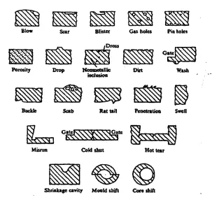
The following defects are most commonly encountered in the sand mould castings (Fig 2.5):
(i)Blow. It is a fairly large, well-rounded cavity produced by the gases which displace the molten metal at the cope surface of a casting. Blows usually occur on a convex casting surface and can be avoided by having a proper venting and an adequate permeability. A controlled content of moisture and volatile constituents in the sand-mix also helps in avoiding the blow holes.
(ii) Scar. A shallow blow, usually found on a flat casting surface, is referred to as a scar.
(iii) Blister. This is a scar covered by the thin layers of a metal.
Buckle Scab Rat tail Penetration Swan
Gate Gate
Cold shut Misrun
■■■■■\.‘s
Hot tear
Shrinkage cavity Mould shift Core shift
L1/4
N
Porosity Drop
Blister
Dross
Nonmetallic inclusion
Gas holes Pin holes
Wash Scar
Blow
(v) Pin holes. These are nothing but tiny blow holes, and occur either at or just below the casting surface. Normally, these are found in large numbers and are almost uniformly distributed in the entire casting surface.
(vi) Porosity. This indicates very small holes uniformly dispersed throughout a casting. It arises when there is a decrease in gas solubility during solidification.
(vii) Drop. An irregularly-shaped projection on the cope surface of a casting is called a drop. This is caused by dropping of sand from the cope or other overhanging projecttions into the mould. An adequate strength of the sand and the use of gaggers can help in avoiding the drops.
(viii) Inclusion. It refers to a nonmetallic particle in the metal matrix. It becomes highly undesirable when segregated.
[image:36.568.168.481.370.669.2](ix) Dross. Lighter impurities appearing on the top surface of a casting are called dross. It can be taken care of at the pouring stage by using items such as a strainer and a skim bob.
(x) Dirt. Sometimes sand particles dropping out of the cope get embedded on the top surface of a casting. When removed, these leave small, angular holes, known as dirts. Defects such as drop and dirt suggest that a well-designed pattern should have as little a part as possible in the cope. Also, the most critical surface should be placed in the drag.
(xi) Wash. A low projection on the drag surface of a casting commencing near the gate is called a wash. This is caused by the erosion of sand due to the high velocity jet of liquid metal in bottom gating.
(xii) Buckle. This refers to a long, fairly shallow, broad, vee-shaped depression occurring in the surface of a flat casting of a high temperature metal. At this high temperature, an expansion of the thin layer of sand at the mould face takes place before the liquid metal at the mould face solidifies. As this expansion is obstructed by the flask, the mould face tends to bulge out, forming the vee shape. A proper amount of volatile additives in the sand-mix is therefore essential to make room for this expansion and to avoid the buckles.
(ciii) Scab. This refers to the rough, thin layer of a metal, protruding above the casting surface, on top of a thin layer of sand. The layer is held on to the casting by a metal stringer through the sand. A scab results when the upheaved sand is separated from the mould surface and the liquid metal flows into the space between the mould and the displaced sand.
(xiv) Rat tail. It is a long, shallow, angular depression normally found in a thin casting. The reason for its formation is the same as that for a buckle. Here, instead of the expanding sand upheaving, the compressed layer fails by one layer, gliding over the other.
(xv) Penetration. If the mould surface is too soft and porous, the liquid metal may flow between the sand particles up to a distance, into the mould. This causes rough, porous projections and this defect is called penetration. The fusion of sand on a casting surface produces a rough, glossy appearance.
(xvi) Swell. This defect is found on the vertical surfaces of a casting if the moulding sand is deformed by the hydrostatic pressure caused by the high moisture content in the sand.
(xvii) Misrun. Many a time, the liquid metal may, due to insufficient superheat, start freezing before reaching the farthest point of the mould cavity. The defect that thus results is termed as a tnisrun.
(xviii) Cold shut. For a casting with gates at its two sides, the misrun may show up at the centre of the casting. When this happens, the defect is called a cold shut.
(xx) Shrinkage cavity. An improper rister may give rise to a defect called shrinkage cavity, as already detailed.
(xxi) Shift. A misalignment between two halves of a mould or of a core may give rise to a defective casting, as shown in Fig 2.7. According, this defect is called a mould shift or a core shift.
2.4 Other Casting Processes
We have so far discussed the basic features of the casting processes mainly with reference to the most common type of green sand mould casting. In this section, we shall consider the other types of casting processes.
2.4.1 Dry Sand Mould Casting
The dry sand mould casting uses expendable moulds, i.e. each mould is used only once. A dry sand mould is basically a green sand mould baked in an oven at 100- 250°C for several hours. The sand-mix contains 1-2% of pitch. The oxidation and polymerization of pitch increases the hot strength of the mould. As the water is driven out from the sand-mix by heating, the defects caused by the generation of steam, e.g. blows and porosity, are less frequent in dry sand mould casting.
2.4.2 Shell Mould Casting
The shell mould casting is a semi-precise method for producing small castings repetitively in large numbers. The mould material contains phenolic resin mixed with fine, dry silica. These are mixed either dry or in the presence of alcohol; no water is used. Normally, a machined pattern of gray iron, aluminium, or brass is used in this process. First, the pattern is heated to 230-260°C, and then the sand-resin mixture is either dumped or blown over its surface. This way, the heated pattern melts and hardens the resin which, in turn, bonds the sand grains closely together. After a dwell time of 20-30 sec, the pattern and sand are inverted. When this happens, a layer of
Two such halves, placed one over the other, make the complete mould. While pouring the liquid metal, the two halves are clamped down together by clamps or springs.
It should be noted that in this process, the smoothness of the mould wall is independent of the moulder's skill. This contributes to a better dimensional accuracy and consistency when compared with green sand moulding. Smooth mould walls also offer less resistance to the flow of liquid metal in the mould. This is why smaller gates can be used. Moreover, thin sections, sharp corners, small projections, which are not possible in green sand moulds, can be accommodated. Further, subsequent machining operations are also reduced. Often, only grinding can produce the finished product. The increased cost of the metal pattern (as compared with the wooden pattern used in green sand moulding), however, can be justified only if the casting is produced in large enough numbers.
2.4.3 Investment Casting
The process of investment casting is suitable for casting a wide range of shapes and contours in small-size parts, especially those that are made of hard-to-machine materials. The process produces excellent surface finish for the casting. Here, the mould is made in a single piece, and consequently there is no parting line to leave out fins. This also adds to the dimensional accuracy of the casting. As will be apparent from the description of the process, no complication arises when withdrawing a pattern from the mould. Though the process is elaborate and expensive, it has been found very suitable for casting turbine and jet engine parts made of high temperature and high strength alloys. We now describe the steps to be followed in this process.
A rather accurately dimensioned metal pattern is used. The dimensions of the pattern are calculated to compensate for the several size adjustments which take place in the process - in the die, in the wax, in the investment material, and, finally, in the casting material. The determination of the pattern dimensions is a tedious task and requires considerable experimentation. This makes the pattern in an investment casting very costly.
inside corners and to drain out the excess slurry. Sometimes, a number of expendable patterns are assembled as a 'tree' for economy. Finally, fine-grain silica sand is sprinkled onto the wet slurry surface. The coating thus produced on the expendable pattern after drying is called a pre-coat.
The pattern with the pre-coat is then placed on a steel base and is covered by an open-ended steel can. Both the pattern and the can are secured to the base by molten wax. Then, the can is filled with a slurry of heavy, self-hardening refractory concentrate. The concentrate sets in after a lapse of 24 hours when the can is placed in an oven. Thus, most of the wax or plastic melts and flows out of the mould, leaving a cavity with the shape of the intended casting. The residual wax is removed by firing the mould in a furnace for about 24 hours.
The liquid metal is poured into this mould while it is still hot. This saves the liquid metal from acquiring the moisture and avoids high thermal gradient between the liquid metal and the mould. In critical cases, the pouring is conducted in a vacuum chamber or in a protective inert atmosphere (such as argon). Frequently, the mould is clamped to a special type of furnace which is then inverted for pouring directly from the furnace into the mould. After cooling, the can is removed and the hard refractory investment is knocked off by a hammer or other vibratory means. Finally, the adhered investment material is removed from the casting surface by sand-blasting or a tumbling operation.
2.4.4 Gravity Die Casting
In gravity die casting, a permanent mould is used. The liquid metal is poured into a non-expendable mould under the force of gravity. The process is normally used for cast iron and, occasionally, for a nonferrous casting. The mould is made of heat resistant cast iron, and is provided with fins on its outer surface for efficient air-cooling. The inner surface of the mould cavity is sprayed with an oil-carbon-silica mixture before each pouring.
2.4.5 Die Casting
die is cooled by water for an efficient cooling of the casting. This also increases the die life. The process is referred to as a hot chamber or a cold chamber (Fig 2.8)
c. Cold chamber.
Figure 2.6 - 2.8 Cold arid Hot Chambers and Injection moulding.
process, depending on whether or not the melting furnace is an integral part of the mould. Since the liquid metal is forced into the die with high external pressure, much thinner sections can be cast by this process. The process, when applied to a plastic casting, is called injection moulding.
2.4.6 Centrifugal Casting
The centrifuge action segregates the less dense nonmetallic inclusions near the centre of rotation.
Figure 2.9: Centrifugal casting
i
I air pressure
--e.
I I
metal--
turnaos casing
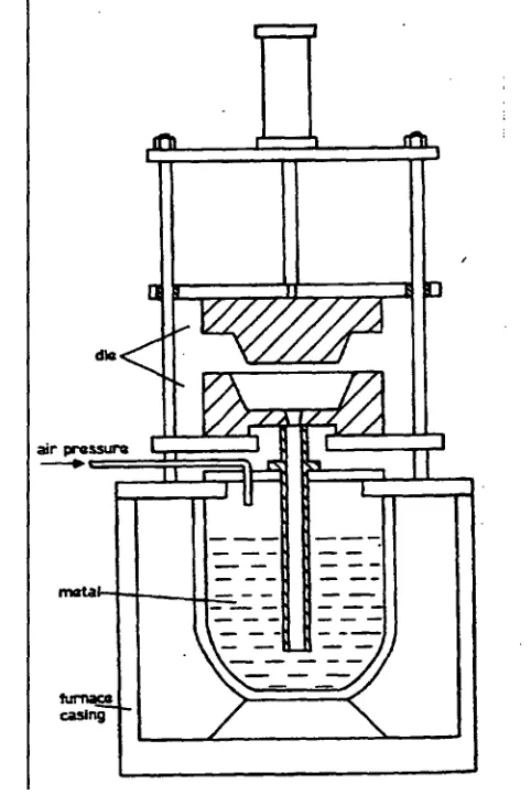
2.4.7 Low pressure die casting
[image:43.568.141.382.337.697.2]Low-pressure die-casting is predominantly used for component manufacture. This includes a wide variety of components such as saucepans, wheels, heads, water pumps, etc. The fundamental advantage of low pressure is its ability to fill a cavity in a controlled manner via the riser tube. Once the die is full the pressure is increased aiding the feed to the cavity. It is normal to have only one feed point to the cavity. This is termed the sprue. The dies that form the cavity are usually multi component. The ability of the dies to eject the cavity and perform mechanical segregation is very important and in many ways more complex than the process itself. The basic principles of low pressure are diagrammatically shown below. A more detailed discussion of low-pressure die-casting is explained later.
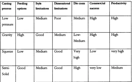
2.5 Casting processes specific to wheels
The following table shows the take up of new technologies to the production of alloy wheels
Table 1 : Approx. breakdown of worlds commercial wheel aluminium casting
processes n •
Casting process for wheels
Commercial production (estimate)
Low pressure 60 %
Gravity 35%
Squeeze/High pressure <5 %
Other- Semi Solid pilot facilities only
From the above breakdown, despite the possibility of new production processes for
wheels the future process improvements will be made through optimising current
production processes. The focus of this thesis is to provide a means to optimise one
part of the process. The process to be focused on is dimensional limitations.