UNIVERSITI TEKNIKAL MALAYSIA MELAKA
Faculty of Electrical Engineering
COMPARATIVE STUDY BETWEEN LINEAR AND INTELLIGENT
CONTROLLERS FOR ANTI-SWAY GANTRY CRANE SYSTEM
FEDA’AADEEN YAHYA MOHAMMED ALKHASHI
Bachelor of Electrical Engineering (Control, Instrumentation and
Automation) with Honor
APPROVAL
I hereby declare that I have read through this report entitled “COMPARATIVE STUDY BETWEEN LINEAR AND INTELLIGENT CONTROLLERS FOR ANTI-SWAY GANTRY CRANE SYSTEM” and found that it has compiled the partial fulfilment for awarding the degree of Bachelor of Electrical Engineering (Control, Instrumentation and Automation).
Signature:
…………...………..
COMPARATIVE STUDY BETWEEN LINEAR AND INTELLIGENT
CONTROLLERS FOR ANTI-SWAY GANTRY CRANE SYSTEM.
FEDA’AADEEN YAHYA MOHAMMED ALKHASHI
B011310369
A report submitted in partial fulfilment of the requirement for the degree
of Electrical Engineering (Control, Instrumentation and Automation)
Faculty of Electrical Engineering
UNIVERSITI TEKNIKAL MALAYSIA MELAKA
DECLERATION
I (Feda’aadeen Yahya Alkhashi) declare that this report entitles “COMPARATIVE STUDY BETWEEN LINEAR AND INTELLIGENT CONTROLLERS FOR ANTI-SWAY GANTRY CRANE SYSTEM” is the result of my research except as cited in the references. The report has not been accepted for any degree and is not concurrently submitted in candidature of any other degree.
Signature:
………
DEDICATION
ACKNOWLEDGEMENT
Firstly, I am grateful that Dr. Rozaimi Bin Ghazali is my supervisor for my Final Year Project. His guidance throughout the period of the final year project is very appreciated. His patience, motivation, and knowledge guide me to the right track of conducting this project. His guidance and corrections on writing the report, has helped me a lot in term of writing a good and qualified technical report. Also, I would like to thank my panels Dr. Azrita bte Alias and Nur Asmiza Binti Selamat.
Secondly, I would like to thank my friends for their enormous assistance and discussion with me throughout this Final Year Project. Through discussion we were able to exchange and share ideas among us, so I gained a lot of meaningful knowledges about my project.
I ABSTRACT
Gantry crane is a transporting machine system used to transport heavy loads and dangerous materials in industries, factories, high building constructors and shipyards. Therefore, controlling such system is very crucial in the working environment that generally caused the safety issues. There are many controllers have been applied to control the system, so selecting the suitable and functional controller has been a critical matter. In this project, the methods or techniques of controlling the gantry crane system is discussed and compared together. Advantages, disadvantages and performance of each controller are studied and introduced as a comparative study. To be more specific, two type of controllers are being chosen for this project as there are widely used in practical life. Linear and intelligent controllers are the ones to be studied in this project. Proportional-integral-derivative controller (PID) and linear-quadratic-regulator controller (LQR) will represent the linear controllers. Fuzzy logic controller and fuzzy-PID controller will represent the intelligent controllers. The findings show that, from the comparative study between linear and intelligent controllers, Fuzzy and Fuzzy-PID show better performance as compared to PID and LQR controllers. The performance in terms of design complexity, transient
response (OS%, Ts, Tp and Tr), steady state error (ess), root-mean-square error (RMSE)
II ABSTRAKT
III
Table of Contents
APPROVAL ... DECLERATION ... DEDICATION ... ACKNOWLEDGEMENT ...
ABSTRACT ... i
ABSTRAKT ... ii
Table of Contents ... iii
List of Figures ... v
List of Tables ... vii
CHAPTER 1 ... 1
1. INTRODUCTION ... 1
1.1 MOTIVATION ... 1
1.2 Problem Statement ... 5
1.3 Objective ... 6
1.4 Scope of Work ... 6
CHAPTER 2 ... 7
2. LITERATURE REVIEW ... 7
2.1 Gantry Crane System ... 7
2.2 Control Techniques in Gantry Crane System ... 7
2.3 Linear Controllers ... 8
2.3.1 PID Controller ... 8
2.3.2 Linear Quadratic Regulator ... 9
2.4 Intelligent Controllers ... 10
2.4.1 Fuzzy Logic Controller ... 10
2.4.2 Neural Networks ... 11
2.5 Robust Controllers ... 12
2.5.1 H∞ Controller ... 12
IV
2.6 Feedforward Controllers ... 14
2.6.1 Open Loop Optimal Strategy ... 14
2.6.2 Input Shaping Technique ... 15
2.7 Summary ... 16
CHAPTER 3 ... 17
3. METHODOLOGY ... 17
3.1 Introduction ... 17
3.2 Project Methodology ... 18
3.3 Modelling of Gantry Crane System ... 20
3.4 PID Controller ... 24
3.5 LQR Controller ... 26
3.6 Fuzzy Logic Controller ... 28
3.7 Fuzzy-PID Controller ... 31
3.8 Evaluation of Performance ... 36
CHAPTER 4 ... 37
4. RESULTS AND DISCUSSION ... 37
4.1 Introduction ... 37
4.2 Linear Controller ... 38
4.2.1 PID & LQR Positioning Result ... 38
4.2.2 PID and LQR Anti-Swaying Result ... 40
4.3 Intelligent Controllers ... 42
4.3.1 Fuzzy and Fuzzy-PID Positioning Result ... 42
4.3.2 Fuzzy and Fuzzy-PID Anti-Swaying Result ... 44
4.4 Evaluation on Linear and Intelligent Controller Performance ... 46
4.4.1 PID, LQR, Fuzzy and Fuzzy-PID Positioning Response ... 46
4.4.2 PID, LQR, Fuzzy and Fuzzy-PID Anti-Swaying Response ... 48
CHAPTER 5 ... 51
5. CONCLUSION AND RECOMMENDATION ... 51
5.1 Conclusion ... 51
5.2 Recommendation for Future Work ... 51
REFERENCES ... 52
APPENDICES ... 54
Appendix A: Gantt Chart for Final Year Project 1 ... 54
V
List of Figures
Figure 1.1: Boom Crane ... 2
Figure 1.2: Tower Crane ... 2
Figure 1.3: Gantry Crane ... 3
Figure 1.4:Crane-Related Deaths in Construction by Year, 1992-2006... 4
Figure 2.1: Fuzzy Controller Structure ... 10
Figure 2.2: Neural Network Block Diagram ... 11
Figure 3.1: Flowchart Diagram of The Project... 19
Figure 3.2: Gantry Crane Simulation Model ... 20
Figure 3.3: Gantry crane physical model... 21
Figure 3.4: Gantry Crane State Space Model ... 22
Figure 3.5: Simulink Setup of Gantry Crane ... 23
Figure 3.6: Parameter Variable Setting ... 23
Figure 3.7: PID controller block diagram ... 24
Figure 3.8: PID Controller Position Parameters ... 25
Figure 3.9: PID Controller Anti-Sway Parameters ... 25
Figure 3.10: Uncompensated Gantry Crane System Response ... 25
Figure 3.11: LQR Design Block Diagram ... 27
Figure 3.12: LQR Controller Simulink Model ... 27
Figure 3.13: Fuzzy Logic Block Diagram ... 28
Figure 3.14: Membership Function of Anti-Swing Control ... 29
Figure 3.15: Membership Function of Position Control ... 29
VI
Figure 3.17: Subsystem of Fuzzy-PID Control Scheme ... 32
Figure 3.18: Membership Function of Fuzzy Input (Error)... 33
Figure 3.19: Membership Function of Fuzzy Input (Error Rate) ... 33
Figure 3.20: Membership Function of Fuzzy Output ... 34
Figure 4.1: Linear Position Response ... 39
Figure 4.2: Linear Swaying Response ... 41
Figure 4.3: Intelligent Positioning Response ... 43
Figure 4.4: Intelligent Swaying Response ... 44
Figure 4.5: Linear & Intelligent Controllers Positioning Response ... 47
Figure 4.6: Linear & Intelligent Controllers Sway Response ... 48
Figure 4.7: Linear and Intelligent Controllers' Position Performance Chart ... 50
VII List of Tables
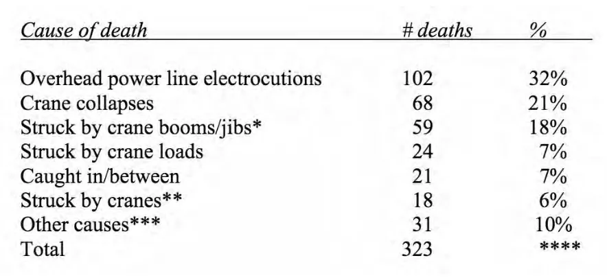
Table 1.1: Reasons of deaths which are related to crane, 1992-2006 ... 4
Table 3.1: Fuzzy Rule Base of Position Control ... 30
Table 3.2: Fuzzy Rule Base of Anti-Swing Control ... 30
Table 3.3: Rules Base Abbreviation ... 30
Table 3.4: Fuzzy Rule Base of Kp ... 35
Table 3.5: Fuzzy Rule Base of Ki... 35
Table 3.6: Fuzzy Rule Base of Kd ... 35
Table 3.7: Rules Base Abbreviation ... 35
Table 4.1: Parameter Analysis for Linear Controllers’ Positioning ... 39
Table 4.2: Parameter Analysis for Linear Controllers' Swaying ... 41
Table 4.3: Parameter Analysis for Intelligent Controllers' Positioning ... 43
Table 4.4: Parameter Analysis for Intelligent Controllers' Swaying ... 45
Table 4.5: Parameter Analysis for Intelligent Controllers' Positioning ... 47
1 CHAPTER 1
1. INTRODUCTION
1.1 MOTIVATION
Transportation becomes one of the most vitally important needs in our life. People, animal and goods are required to move from one place to another in order to fulfill their necessity. Things can be transported through many ways such air, road, rail, water, cable, pipelines and space. Nowadays, all of the factories, ports and plants require systems to transport goods and equipment within their working area. Besides, safety is the most concerning and crucial aspect most of the factories and other infrastructures care about. One of the machines that is worldwide used to transport heavy loads and dangerous materials in industries, factories, high building constructors and shipyards is crane system. There are two main types of crane which are rotary crane and gantry crane.
Rotary crane differs from the gantry crane where its load-line attachment point undergoes rotation. It has two types, boom crane which is used in shipyards and the point moves vertically for this type as shown in Figure 1.1. The other type is tower crane which is mostly used in construction as illustrated in Figure 1.2. Besides these motions, the cable can be controlled either to get lowered or raised. Like a spherical pendulum with two-degree-of-freedom sway, the load and cable can be treated.
2
Figure 1.1: Boom Crane
[image:15.595.154.458.321.525.2]3
[image:16.595.168.440.278.486.2]Gantry crane as illustrated in Figure 1.3 is the other type of cranes that highly utilized in heavy engineering machinery. It mainly consists of three parts which are trolley, cable and payload. The trolley moves horizontally while the payload is attached by the rope whose length can be changed by lifting techniques. The cable attached together with the load is considered as one-dimensional pendulum with one-degree-of-freedom. There is another kind of these type of cranes, which also can move horizontally but in two perpendicular directions. The analysis is almost the same for all of them due to that the two-direction movements can be divided into two uncoupled one-direction motions.
Figure 1.3: Gantry Crane
4
Figure 1.4:Crane-Related Deaths in Construction by Year, 1992-2006
[image:17.595.87.529.428.632.2]5 1.2 Problem Statement
Despite the fact that there are many ways to improve the operation and functionality of the cranes, there are also major problems associated with the improving processes. One of the most crucial and challenging problems is the load sway in the crane during movement. Oscillation and swaying of a heavy load may cause dangerous and serious bad consequences. Property’s damaging and human injuries and deaths are the probable result of such problem. The conventional solution will be based on the feeling, experience and observation of the operator. Very high expertise and proficiency are required for the workers to be qualified controlling the sway and oscillation of the crane’s load.
6 1.3 Objective
This project will aim to achieve the following objectives:
i) To establish the mathematical modeling of one degree of freedom gantry crane
system.
ii) To design linear and intelligent controllers that capable to track the desired tracking
trajectory while reduce the payload oscillation.
iii) To evaluate the performance of linear and intelligent controllers in term of time response, steady state error and maximum oscillation.
1.4 Scope of Work
The scope of this project will focus on the following points:
i) The gantry crane system only considered 1-DOF that consist of payload
connected using fixed rope length and driven by trolley.
ii) PID and LQR will be implemented as linear controller
iii) Fuzzy and Fuzzy-PID will be implemented as intelligent controller
iv) The performance will be evaluated in terms of design complexity, transient
response performance (OS%, Ts, Tp), steady state error (
e
ss), root-mean-square7 CHAPTER 2
2. LITERATURE REVIEW
2.1 Gantry Crane System
When it comes to applying the gantry crane to the field of work, the efficiency of production will get affect badly by the load oscillation and might cause hazardous accidents. Moreover, beside the high-efficiency and productivity need, the solution of anti-sway for the crane to get over the difficulty that delayed the goods from positioning and transferring professionally is considered to be something vitally important and urgent. Therefore, the anti-sway measures study for the the crane swinging utensils appears to be more important and essential than ever [2].
In terms of the anti-sway means, there are two general categories for the gantry crane: the mechanical and the electronic. The electronic becomes the primary measure and research focus in the field of the oscillation proof, and takes on a great deal of unparalleled superiority over its mechanical counterpart [2].
The first method used for anti-swaying was introduced in 1930 by Lueg [3]. As a way to cancel noise vibration, the researcher used the active control technique. Controlling an active sway angle of gantry crane contains artificially generating sources which works on absorbing the energy resulted from the undesired rope’s sway angle to eliminate or decrease the impact on the whole system.
2.2 Control Techniques in Gantry Crane System
8 2.3 Linear Controllers
2.3.1 PID Controller
Proportional-Integral-Derivative (PID) controller is considered to be one of the feedback controller and as stated in [5], due to its simplicity PID controller has been commonly used in feedback control system design. Its output depends on the difference between the set point of the system and the measured process variable. Every part of the PID controller has to do a certain action taken on the error. Then, the error is used to modify some of the process input in order to get its defined set point.
However, the PID method is not suitable for controlling a system with large amount of lag, parameter variations and uncertainty in models. Thus, PID control method cannot accurately control position in a hydraulic system. To improved PID control performance, many researchers have integrated fuzzy Logic Control technique to tune the PID parameter.
In [6], proportional-integral-derivative (PID) controller is utilized with high convenience and ordinary usage for user. As a result, it has been widely and extensively used in actual and real industries. PID controller has been designed for crane automatic position and anti-sway in order to consider nonlinear elements of an Air Traffic Control (ATC). An automatic change in varying conditions must happen to the PID parameters, as
transfer crane has many dynamic characteristics. Nevertheless, PID controller has low
9 2.3.2 Linear Quadratic Regulator
Linear Quadratic Regulator (LQR) controllers have been proposed as a solution to some of the PID controller problems in [7]. Applying LQR controller to a system will result in a good and suitable performance and outcomes related to a given performance measure. This measure of performance is considered to be a quadratic function consist of two factors which are control input and state vector.
Pole positioning method theory is well carried out by LQR. There are two functions that the LQR algorithm can define the pole positioning theory based on. First stating the optimal performance index and second solving the algebraic Riccati equation. Iteration method should be the way to define the cost function of the gain as there’s no specific solution LQR can provide to define it.
10
Figure 2.1: Fuzzy Controller Structure 2.4 Intelligent Controllers
2.4.1 Fuzzy Logic Controller
In[2], fuzzy logic controller has been one of the techniques that have been proposed by many studies and researchers. Fuzzy logic controller was fully able to realize the horizontal positioning control precisely. The experimental results indicated that this system is capable of both the precise positioning and angle attenuation within a less time period and with less disturbance ability.
Moreover, in [8] the proposed fuzzy logic controllers consist of two main parts which are position controllers and anti-swing controllers. The information of the professional operators was the base of the fuzzy logic control’s design. The intelligent controller’s performance is experimentally evaluated and calculated on a lab-scale of gantry crane. Compared to a gantry crane system operated with classical PID controller, the gantry crane controlled by fuzzy logic controller showed a better performance in the experimental result.
11 Plant
Neural Network Model
Learning Algorithm
𝑢 𝑦𝑝
𝑦𝑚
2.4.2 Neural Networks
According to [9] and [20], Neural networks have been adopted for the dynamical system’s control and used in divers fields and spaces like prediction, recognition and classification. Neural-network-based, self-tuning controllers has been proposed for overhead cranes. Moreover, a novel method for overhead cranes’ trajectory planning was introduced in order to alleviate the oscillation and sway motion after moving to the last destination. To generate the trolley position’s optimal trajectory, radial basis function networks have been utilized. Lately, an algorithm called particle swarm optimization (POS) has been used to learn and evaluate the neural network’s parameters. POS is an evolutionary computation technique. It’s been adopted to train the radial basis function network. By moving the trolley along the generated track, the reduction of sway angle can be achieved smoothly; that is, the proposed control scheme does not require sensors to measure the undesired oscillation as it’s an open loop control. Figure 2.2 indicates the schematic of the neural network.
[image:24.595.90.440.402.599.2]