with carbon capture: part-load operation scenarios in the context of EOR
.
White Rose Research Online URL for this paper:
http://eprints.whiterose.ac.uk/133053/
Version: Published Version
Proceedings Paper:
Gonzalez Diaz, A., Fernandez, E.S., Gibbins, J. orcid.org/0000-0003-0963-4555 et al. (1
more author) (2017) Sequential supplementary firing in combined cycle power plant with
carbon capture: part-load operation scenarios in the context of EOR. In: 13th International
Conference on Greenhouse Gas Control Technologies, GHGT-13. 13th International
Conference on Greenhouse Gas Control Technologies, GHGT-13, 14-18 Nov 2016,
Lausanne, Switzerland. Energy Procedia (114). Elsevier , pp. 1453-1468.
https://doi.org/10.1016/j.egypro.2017.03.1901
eprints@whiterose.ac.uk https://eprints.whiterose.ac.uk/
Reuse
This article is distributed under the terms of the Creative Commons Attribution-NonCommercial-NoDerivs (CC BY-NC-ND) licence. This licence only allows you to download this work and share it with others as long as you credit the authors, but you can’t change the article in any way or use it commercially. More
information and the full terms of the licence here: https://creativecommons.org/licenses/
Takedown
If you consider content in White Rose Research Online to be in breach of UK law, please notify us by
1876-6102 © 2017 The Authors. Published by Elsevier Ltd. This is an open access article under the CC BY-NC-ND license (http://creativecommons.org/licenses/by-nc-nd/4.0/).
Peer-review under responsibility of the organizing committee of GHGT-13. doi: 10.1016/j.egypro.2017.03.1901
Energy Procedia 114 ( 2017 ) 1453 – 1468
ScienceDirect
13th International Conference on Greenhouse Gas Control Technologies, GHGT-13, 14-18
November 2016, Lausanne, Switzerland
Sequential supplementary firing in combined cycle power plant with
carbon capture: part-load operation scenarios in the context of EOR
Abigail González Díaz
a,b*, Eva Sanchez Fernandez
c, Jon Gibbins
a, and Mathieu
Lucquiaud
aa
The University of Edinburgh, school of Engineering, The King’s Building, Edinburgh EH9 3JL
b
Instituto Nacional de Electricidad y Energias Limpias, Reforma 113, col. Palmira, Cuernavaca Morelo, Mexico. C.P. 62490.
C
Herriot-Watt University, Edinburgh, UK
Abstract
This paper extends previous work on sequential supplementary firing combined cycles (SSFCC) and evaluates their part-load operation in order to define operating strategies to maximise revenue from electricity and Enhanced Oil Recovery (EOR) over a range of fuel input. Sequential supplementary firing consists of burning additional fuel at different stages in the heat recovery steam generator (HRSG) to increase CO2 concentration reduces the
volumetric flow of the flue gases. It uses almost all of the oxygen in the flue gas and keeps the maximum gas temperature at around 820°C to avoid large additional capital costs in the HRSG. SSFCC This analysis is important in order to establish ways to maintain a minimum CO2 flow for EOR when the power plant with CO2 capture is at
minimum stable generation.
Two alternatives to reduce power at part-load are evaluated: a subcritical steam cycle with a combination of variable inlet guide vanes and reduction in supplementary firing; and a strategy where the gas turbine is maintained at full output and the power output is solely reduced by adjusting the amount of supplementary firing in the HRSG.
© 2017 The Authors. Published by Elsevier Ltd.
Peer-review under responsibility of the organizing committee of GHGT-13.
Keywords: Sequential supplementary firing; CO2 capture; part-load operation
* Corresponding author. Tel.: +52 7773623811
E-mail address: abigail.gonzalez@iie.org.mx
© 2017 The Authors. Published by Elsevier Ltd. This is an open access article under the CC BY-NC-ND license (http://creativecommons.org/licenses/by-nc-nd/4.0/).
1. Introduction
Previous work by Gonzalez et al [1] showed that Sequential Supplementary Firing Combined Cycles (SSFCC) compare favourably with natural gas combined cycle (NGCC) power plants integrated with MEA-based CO2
capture, in the context of CO2 sales for EOR in Mexico. Results from the study confirmed that the revenues from
additional CO2 production compared to conventional configurations could contribute to facilitating a roll-out of CCS
in electricity sector in Mexico, and in other markets with EOR and low natural gas prices. Sequential combustion makes use of the excess oxygen in gas turbine exhaust gas to generate additional CO2, but, unlike in conventional
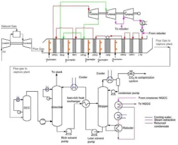
supplementary firing, allows keeping gas temperatures in the heat recovery steam generator below 820°C, avoiding a step change in capital costs. It marginally decreases relative energy requirements for solvent regeneration and amine degradation. Power plant models integrated with capture and compression process models of subcritical SSFCC gas-fired units show that the efficiency is 43% LHV compared to a conventional natural gas combined cycle power plant with the same capture technology of 51%. Although the efficiency is lower than the conventional configuration, the increment in the power output of the combined steam cycle leads a reduction of the number of gas turbines, at a similar power output to that of a conventional natural gas combined cycle. This has a positive impact on the number of absorbers and the capital costs of the post combustion capture plant by reducing the total volume of flue gas by half on a normalised basis. The relative reduction of overall capital costs is 15.3% for the subcritical combined cycle configuration with capture compared to a conventional configuration. For a gas price of $2/MMBTU, the Total Revenue Requirement (TRR) - a metric combining levelised cost of electricity and revenue from EOR – of subcritical sequential supplementary firing is consistently lower than that of a conventional NGCC by 2.2 $/MWh at 0 $/tonneCO2 and by 4.9 $/MWh at $50/tonneCO2 [1]. The schematic diagram and the pinch
[image:3.544.95.449.325.613.2]diagram at 100% are shown in Figure 1 and Figure 2.
Fig. 2 Temperature/heat diagram of the Heat Recovery Steam Generator of a five stage sequential supplementary firing configuration with a single pressure HRSG, with a single reheat combined cycle and subcritical steam conditions (601.7°C, 601.5°C, 172.5 bar). The three pinch
temperatures T1, T2, T3 are respectively 79ºC, 70ºC, 76ºC.
Power plants operate at part-load due to variations in electricity demand caused by weather conditions, seasonal, daily and hourly changes in demand, e.g. there is a difference between week days and weekend days [2]. In the future, the electricity demand will also be influenced by the introduction of variable output renewable energy. It is expected that the installed wind power capacity will increase from 3.1% in 2014 to 12.7% in 2029 [2]. One characteristic of NGCC power plants is their flexibility to change power output according to electricity demand [3]. Therefore, it is necessary to evaluate and to ensure the continuity of flexibility in the operation of new alternatives proposed to decarbonise the electricity market. This paper is focused on evaluating SSFCC at part-load in order to ensure that it would not impose a constraint to this need for flexibility.
2. Modelling of the sequential supplementary firing power plant
The part-load modelling of the NGCC and SSFCC power plants developed in this study has four main units: the gas turbine, the HRSG, the steam cycle, and the capture plant and compressor unit. Their operation and the interaction with respectively the steam cycle and the desorber is very important [4]. The gas turbine used in this work is the 9FB; the performance is taken from Thermoflow [5] data and validated with information from a thermal test of the 9FB published by [6]. Thermoflow is a suite of software which includes GT PRO, GT MASTER and Thermoflex programmes. GT PRO utilises a database of gas turbines with mapped performance curves taken from the manufactures [3]. The model for the HRSG and steam turbines of the NGCC is based on typical modelling principles, such as Stodola ellipse low for steam turbines, heat transfer fundamentals in the HRSG, and relevant pressure drop equations. In order to solve the equation system, the number of equations must be equal to the number of variables. The equation system is solved in Aspen Plus® to estimate the steady state performance at design and part-load conditions using an equation oriented approach.
Steam turbine. Most steam turbines in combined cycle plants operate by sliding pressure operation and generally
兼岌聴
兼岌聴待噺
撃博捲喧銚
撃帖
博博博捲喧銚待俵
喧銚待捲懸銚待
喧銚捲懸銚 標
な 伐 嵳喧栂
喧銚嵳 津袋怠
津
な 伐 嵳喧栂待
喧銚待嵳 津袋怠
津
(1)
Where 兼岌聴 is the steam mass flow (kg/s), 喧 is the pressure (bar), 懸 specific volume (m3/kg), 撃博 average swallowing capacity, 券 is the polytrophic exponent, and the suffix 0 is the design point, 欠 inlet, and 拳 outlet of the steam turbine. In steam turbines, the absolute difference between the inlet and the outlet pressure is large so that the pressure ratio Pw/Pa is small and the ratio of the absorption capacity is close to 1. Equation 2 can then be simplified to Equation 3.
兼岌聴
兼岌聴待噺 俵
喧銚待捲懸銚待
喧銚捲懸銚 (2)
At part-load operation, the mass flow of steam generated is reduced and this equation is used to calculate the pressure across the turbine, and by extension the pump heads.
Overall heat-transfer coefficient. Two equations are needed to predict the behavior of all heat exchangers in the
HRSG and the condenser [9]. The first one is the energy balance between the streams, considering heat loss by radiation and convection from the HRSG representing by Equations 3 and 4. The second equation is the heat transfer across the heat exchanger surface given by Equation 6 [10, 11].
芸 噺 "兼塚"岫月塚墜通痛伐 月塚沈津岻 (3)
芸 噺 "兼直"盤月直墜通痛伐 月直沈津匪 (4)
If a counter-flow exchanger is used, the heat transfer equation allows calculating the product of the overall heat-transfer coefficient U and the exchange surface A by means of a logarithmic mean temperature difference, as in Equation 5. UDA is calculated at design condition and the new UA at part-load is calculated using the correlation
shown in Equation 6.
芸 噺 戟畦盤劇直沈津伐 劇塚墜通痛匪 伐 盤劇直墜通痛伐 劇塚沈津匪 健券 磐劇劇直沈津伐 劇塚墜通痛
直墜通痛伐 劇塚沈津卑
(5)
For economizers and evaporators
戟墜椎畦
戟帖畦 噺 峭
兼直墜椎
兼直帖嶌 陳
(7)
For superheaters, Equation 7 is
戟墜椎畦
戟帖畦 噺 峭
兼直墜椎
兼直帖嶌 陳
磐兼兼塚墜椎
塚帖卑 津
"
Where Q heat transfer (kW), Tg is the temperature gas side (K), Tv is temperature vapour side (K), hg Enthalpy
gas side (kJ / s), hv is the enthalpy vapour side (kg/s), mg is the mass flow of the gas (kg /s), mv is the mass flow of
the steam (kg /s), UD is the overall heat-transfer coefficient at design condition (kW /m2 K), Uop is the overall
朕寧帖日
賃寧 噺 ど どにぬ 峙
帖日弔寧
禎寧峩
待 腿
鶏堅塚待 戴戴 [8]
朕虹帖
賃虹 噺 ど ね 釆
帖弔虹
禎虹挽
待 滞
鶏堅直待 戴戴 [9]
Where 月塚 is the heat transfer coefficient of the steam, (W/m2K), 月直 is the heat transfer coefficient of the gas, (W/m2K), 罫塚 is the steam mass flux, (kg/m2s), 罫直 is the gas mass flux, (kg/m2s), 経沈 is the diameter inside the tube (m), 経 is the tube diameter (m), 倦塚 is the thermal conductivity of the steam W/mK), 倦直 is the thermal conductivity of the gas (W/mK), 航塚 is the viscosity of the steam (kg/ms), 航直 is the viscosity of the gas (kg/m s), 鶏堅塚 is the Prandtl number steam side, 鶏堅直 is the Prandtl number gas side.
In the evaporator, a phase transition from water to steam occurs, which means that the Equation 4 must be replaced by Equation 10.
芸 噺 "兼塚"盤ッ月勅塚銚椎墜追銚痛沈墜津匪 [10]
Where ッ月勅塚銚椎墜追銚痛沈墜津 is the evaporation enthalpy (kW). The ッ月勅塚銚椎墜追銚痛沈墜津 depends on the saturation pressure. The steam mass flow rate in the HRSG of the NGCC and subcritical SSFCC configurations at part-load is calculated taking into account the capacity of the evaporators to convert the water from saturated liquid to saturated vapour and the fact that the separation between the gas and the liquid phase in evaporators occurs through gravity. The steam mass flow rate in the HRSG of the NGCC and subcritical SSFCC at part-load is calculated considering the capacity of the size of the evaporators to convert the water from saturated liquid to saturated vapour. This is possible considering an additional assumption in the system: fully saturated vapour leaves the outlet of HP, IP, and LP boilers in a conventional NGCC and at the outlet of the HP boiler in subcritical SSFCC Figure 1.
Pressure drop. The pressure drop for each heat exchanger is estimated from a simple flow – pressure drop
relationship given by Equation 11, where the equipment parameter is the loss coefficient k. At design condition the constant k is calculated using the pressure, temperature, and mass flow provided at full load after the optimisation. At part-load, k is keeping constant and now the variable calculated is the pressure at the outlet of the heat exchanger.
This equation is used to estimate the pressure drop from the cross-over pipe where steam is extracted for solvent regeneration to the solvent reboiler of the capture plant, which includes the pressure drop through the pipeline and de-superheating. The de-superheater is a heat exchanger to convert the steam going to the reboiler into saturation conditions.
ッ喧 噺 " 鶏沈津伐 鶏墜通痛噺 "倦兼態
な 貢沈津髪 な貢墜通痛
に
[11]
Where
ッ喧 Pressure drop of steam through the heat exchanger (Pa) m Mass flow rate (kg/s)
貢沈津and 貢墜通痛 Density at the inlet and outlet respectively (kg/m3)
k A constant (1/m4)
3. Part-load Operation of sequential supplementary firing combined cycle with CO2 capture
plants. These two operating strategies are modelled in this article:
a. A combination of variable IGV in the gas turbine compressor and adjusting the amount of fuel in the burners of the HRSG
b. Fixed IGV with the gas turbine operating at full load. The load of the power cycle, and by extension the net total power output, is controlled by varying the amount of the supplementary fuel in the burners in the HRSG
In both cases, the HRSG boiler is operated at part-load with sliding pressure.
The operating strategy of the SSFCC power plant is novel, since supplementary firing adds a level of permutation not encountered in conventional configurations. The selected configuration and operation strategy of CO2 capture, compressor units, and the integration strategy between the power plant and the capture unit are based
on [7, 14, 15, 16]. [7] evaluated two capture plant integrations:
- Controlled extraction by throttling the LP steam turbine, or fixed crossover pressure operation, and - uncontrolled extraction with a floating IP/LP crossover pressure, as initially proposed in [17]
The latter is used in this study. Sanchez Fernandez and co-workers show that uncontrolled steam extraction provides better part load performance when compared to controlled extraction. The steam extraction pressure is directly related to the amount of steam extracted. The initial IP/LP crossover pressure is set so that, when the predicted amount of steam is extracted for solvent regeneration, its pressure falls or ‘floats’ to the desired value.
[image:7.544.62.475.332.466.2]Part-load operating strategies of the various elements of SSFCC gas-fired power plant with carbon capture are summarised in table 1, where a conventional strategy of the NGCC is included for the purpose of comparing with subcritical SSFCC case.
Table 1. Lists of option for part-load operation for the power plant, CO2 capture, and compressor unit
Power plant case NGCC Subcritical SSFCC
Gas turbine control Variable IGV Fixed IGV Variable IGV
HRSG No supplementary firing Sequential supplementary firing
Sequential supplementary firing
Steam cycle (Pressure and
temperature) Subcritical Subcritical Subcritical
Steam cycle control Sliding pressure Sliding pressure Sliding pressure
Steam extraction Uncontrolled extraction Uncontrolled extraction Uncontrolled extraction
Capture plant Constant stripper pressure, variable reboiler Temperature and L/G for all cases
CO2 compressor IGV with CO2 recycle valve and constant pressure ratio (Pinlet and Poutlet constant)
IGV = Inlet Guide Vanes; HRSG = Heat Recovery Steam Generation; L/G = Liquid to gas ratio in the absorber; NGCC= Natural Gas Combine Cycle; SSFCC= Sequential Supplementary Firing Combined Cycle
4. Results and discussions
4.1Gas turbine operation with variable inlet guide vanes
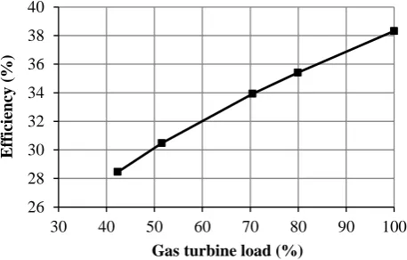
increasing with decreasing load because of the reduction in the efficiency of the gas turbine shown in Figure 5. Below 80% load the air / fuel ratio increases in order to avoid a dramatic increment of the TET. Figure 3 shown that, at approximately 50% load, the increment over the design TET is 45°C. This value is in good agreement with [13, 7] where the maximum TET increment permissible is 50° above nominal ISO.
Fig 3. Gas turbine part-load operation with variable inlet guide vanes (IGV): Turbine Exhaust temperature for a range of loads and air/fuel ratios
Fig 4. Gas turbine part-load operation with variable inlet guide vanes: Turbine inlet temperature for a range of loads and air/fuel ratios 560 570 580 590 600 610 620 630 640 650 45 46 47 48 49 50 51 52 53 54 55
40 50 60 70 80 90 100
Tem p eratu re ex haust ( ° C) a ir /fu el (-)
GT load %
air/ fuel TET
1160 1180 1200 1220 1240 1260 1280 1300 1320 1340 1360 45 46 47 48 49 50 51 52 53 54 55
30 40 50 60 70 80 90 100
Inlet Tem pera ture ( ° C)
air /fuel (
-)
Gas turbine load %
air/ratio TIT
Maximum temperature
Fig 5. Part-load efficiency of the gas turbine
4.2 Combined cycle and heat recovery steam generator operation.
This section describes the part-load performance of a configuration where the desired load of the power cycle is achieved by two alternatives:
1. By using inlet guide vanes and reducing the supplementary fuel in the duct burners
2. By reducing the supplementary fuel in the duct burners with the gas turbine at full load (fixed IGV)
Reducing the minimum load at which a steam turbine can reliably operate is one way of optimising revenue for marginal base-load units during periods of low electrical demand. Although it is not unusual to operate power plants at load levels below the typical 25% with respect to full-load limits, steam turbines may experience undesirable damage at low flow conditions [18]. Under severe low flow conditions, the LP stages will subtract net power due to windage and freewheeling causing a significant temperature rise of the materials of the rotating and stationary components. Information of the allowable minimum steam flow steam turbine is commercial in confidence and is not provided by manufacturers in the public domain. [19] indicates that operation of the LP steam turbine above 20% is acceptable.
The reduction in gas temperature at the outlet of each burner of Figure 1 is shown in Figure 6. At 100% load, the main fuel demand is in the last two burners where the HP evaporator is located. A large amount of heat is needed to change the phase from saturated liquid to saturated vapor. The air / fuel ratio is shown in Figure 8, illustrating that combustion is leaner at 100% load, and the percentage of O2 and CO2 at part-load across the HRSG is shown in
Figure 9 and Figure 10. 26 28 30 32 34 36 38 40
30 40 50 60 70 80 90 100
E
fficiency (%)
Fig 6. Flue gas temperature across the HRSG at part-load for a subcritical SSFCC power plant with fixed IGV and sliding pressure in the HRSG. The flue gas temperature in each duct-burner varies with the changes in load of the power plant, caused by variations of the natural gas mass flow
and subsequent reductions of steam flow
Fig7. Variation of the natural gas mass flow across the HRSG at part-load of a subcritical SSFCC power plant with fixed IGV and sliding pressure in the HRSG
350 400 450 500 550 600 650 700 750 800 850
40 50 60 70 80 90 100
Tem
pera
ture (
°
C)
Load (%)
Duct burner 1 Duct burner 2 Duct burner 3 Duct burner 4 Duct burner 5
0 4 8 12 16 20 24
40 50 60 70 80 90 100
M
a
ss flow
ra
te
o
f
n
a
tu
ra
l
g
a
s
(t/h
)
Load (%)
Duct burner 1
Duct burner 2
Duct burner 3 Duct burner 4
Fig 8. air / fuel ratio in each duct-burner at part-load for a subcritical SSFCC power plant with fixed IGV and sliding pressure. The variations are caused by a reduction of the natural gas mass flow to accommodate subsequent reductions of steam production
Fig 9. Variation of CO2 concentrations across each section of the HRSG at different loads for a subcritical SSFCC with fixed IGV and sliding pressure in the HRSG. The acronyms used refer to Figure 1
0 400 800 1200 1600 2000 2400 2800
40 50 60 70 80 90 100
Air ratio
Load (%)
Duct burner 1
Duct burner 2
Duct burner 3
Duct burner4
Duct burner5 Fuel = 0 kg/s
Fuel = 0 kg/s
Fuel = 0 kg/s
Fuel = 0 kg/s
0 2 4 6 8 10 12
0 1 2 3 4 5 6
CO
2
co
n
cen
tra
tion
(%
)
Section of the HRSG
100% 83% 72% 58%
HPSP3 - RH2
RH1 - HPSP2
HPSP1 EVA HPE2 -
[image:11.544.142.385.285.468.2]Fig 10. Variation of O2 concentration across each section of the HRSG at different loads for a subcritical SSFCC with fixed IGV and sliding pressure in the HRSG. The acronyms used refer to Figure 1
4.3 CO2 capture plant and compression unit
The CO2 capture plant is simulated in Aspen plus ®
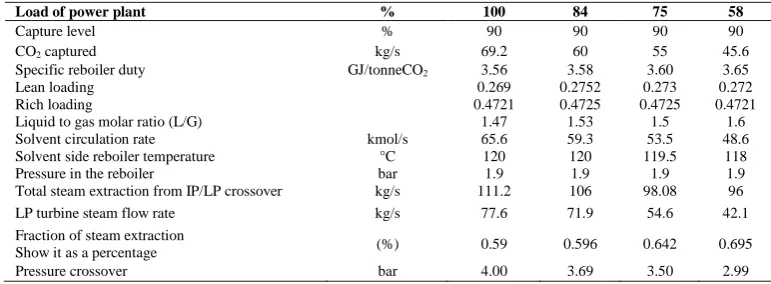
using a rate-based approach. A summary of relevant parameters for the part-load operation of a conventional NGCC plant with capture are shown in Table 2. The small reduction of the solvent temperature in the reboiler at load below 75%, is not favourable to the vapour-liquid equilibrium in the stripper because the extent of solvent regeneration is reduced and leads to higher CO2 lean
loading, as explained in [4]. The lean loading increases from 0.269 to 0.272 as indicated in Table 2 and the specific reboiler duty increases marginally from 3.56 to 3.65 GJ/tonneCO2. At higher lean loadings, a larger L/G is needed to
achieve the same 90% of CO2 removal. The L/G is adjusted at each load to get 90% of CO2 capture. It is increased
[image:12.544.78.464.445.587.2]from 1.47 to 1.6 when reducing load from 100% to 58%. This leads to providing more energy to compensate for the increase contribution of the sensible heat of the solvent to raise the temperature of the solvent to the stripper temperature.
Table 2. Capture plant process simulation at part-load of conventional natural gas combined cycle
Load of power plant % 100 84 75 58
Capture level % 90 90 90 90
CO2 captured kg/s 69.2 60 55 45.6
Specific reboiler duty GJ/tonneCO2 3.56 3.58 3.60 3.65
Lean loading 0.269 0.2752 0.273 0.272
Rich loading 0.4721 0.4725 0.4725 0.4721
Liquid to gas molar ratio (L/G) 1.47 1.53 1.5 1.6
Solvent circulation rate kmol/s 65.6 59.3 53.5 48.6
Solvent side reboiler temperature °C 120 120 119.5 118
Pressure in the reboiler bar 1.9 1.9 1.9 1.9
Total steam extraction from IP/LP crossover kg/s 111.2 106 98.08 96
LP turbine steam flow rate kg/s 77.6 71.9 54.6 42.1
Fraction of steam extraction
Show it as a percentage (%) 0.59 0.596 0.642 0.695
Pressure crossover bar 4.00 3.69 3.50 2.99
Table 3 shows the most important parameters of the capture plant of a subcritical SSFCC operated at part-load. The behaviour is similar to that of a conventional NGCC when operating between 100% and 75% load. However, the crossover pressure between the IP and LP turbine is 2 bar at 58%, which is lower than in the conventional
0 2 4 6 8 10 12 14
0 1 2 3 4 5 6
O2
concentratio
n (%
)
Section of the HRSG 100% 83% 72% 58%
HPSP3 -
RH2 HPSP2RH1 -
HPSP1 EVA HPE2 -
NGCC configuration (3 bar) at the same load. The strategy proposed by Sanchez Fernandez et al (2016) is then adopted, where “a combination of releasing stripper pressure and increasing the L/G ratio in the absorber” is used.
Table 3. Capture plant process simulation at part-load of conventional natural gas combined cycle
Load of power plant % 100 84 75 58
Capture level % 90 90 90 90
CO2 captured kg/s 69.2 60 55 45.6
Specific reboiler duty GJ/tonneCO2 3.56 3.58 3.60 3.65
Lean loading 0.269 0.2752 0.273 0.272
Rich loading 0.4721 0.4725 0.4725 0.4721
Liquid to gas molar ratio (L/G) 1.47 1.53 1.5 1.6
Solvent circulation rate kmol/s 65.6 59.3 53.5 48.6
Solvent side reboiler temperature °C 120 120 119.5 118
Pressure in the reboiler bar 1.9 1.9 1.9 1.9
Total steam extraction from IP/LP crossover kg/s 111.2 106 98.08 96
LP turbine steam flow rate kg/s 77.6 71.9 54.6 42.1
Fraction of steam extraction
Show it as a percentage (%) 0.59 0.596 0.642 0.695
Pressure crossover bar 4.00 3.34 2.75 1.90
[image:13.544.156.380.295.511.2]Figure 11 shows the reduction of the crossover pressure causing lower operating temperatures in the reboiler and increasing the reboiler duty. At 58% load, the stripper pressure has to be released from 1.87 bar to 1.63 bar. The reboiler duty then increases from 3.44 MJ/tonne CO2 to 3.88 MJ/tonne CO2.
Fig 11. Reboiler duty and reboiler solvent temperature vary with changes in crossover pressure, caused by a reduction of steam cycle flow at part-load between 100% and 60% part-load, with 90% capture in the subcritical SSFCC with fixed IGV
0.5 1.0 1.5 2.0 2.5 3.0 3.5 4.0 4.5
3.4 3.5 3.6 3.7 3.8 3.9 4.0
107 110 113 116 119 122
Crossover press
ure
(bar)
Rebo
iler duty (M
J
/ tonne CO
2
)
Reboiler temperature (°C)
Pressure
Table 4. Capture plant process simulation at part-load of subcritical SSFCC sliding pressure boiler
Load of power plant % 100 85 75 58
CO2 captured kg/s 87.7 73.7 63.4 50.3
Capture level % 90 90 90 90
Specific reboiler duty GJ/tonneCO2 3.44 3.44 3.52 3.88
Lean loading 0.2821 0.284 0.3137 0.3623
Rich loading 0.4806 0.4785 0.4727 0.449
Liquid to gas molar ratio (L/G) 4.03 3.73 3.89 5.43
Solvent circulation rate kmol/s 76.8 72.8 76.8 109.4
Solvent side reboiler temperature 120 119.0 117.3 110
Pressure in the reboiler bar 1.87 1.87 1.87 1.64
Total steam extraction from IP/LP crossover
to capture plant kg/s 138 115 100 100
LP turbine steam flow rate kg/s 237.6 182.8 144.6 67.7
Fraction of steam extraction kg/s 0.37 0.39 0.41 0.60
Crossover pressure bar 4 3.34 2.75 1.90
Two trains with a similar gear-type centrifugal compressor with seven stages and intercooling after each stage are used in all configurations to compress the produced CO2 to 150 bar for EOR purposes. The inlet and outlet
pressures in each stage of the compressor are constant at part-load for the conventional NGCC and for the subcritical SSFCC between 100% and 75%. However, for SSFCC configuration at 58% load, as the pressure in the stripper is released, the inlet pressure of the first stage of the compressor reduces. Below 75% load, a fraction of the compressed CO2 must be recycled in order to avoid surge and prevent damage to the compressor (Liebenthal and
Kather, 2011; Kiameh, 2013). Recycling compressed CO2 increases the auxiliary electricity consumption. Table 5
summarises the auxiliary power consumption of the CO2 compression unit at various load.
Table 5. Auxiliary power consumption of the CO2 compressor unit at part-load operation
Load of power plant % 100 85 75 58
NGCC MW 22.38 21.31 20.00 19.8
Subcritical SSFCC MW 31.57 31.67 23.32 23.30
5. Variation of the efficiency at part-load
One strategy to maximize power output at part-load with sequential supplementary firing is to operate the gas turbine at full load to maintain high efficiency and adjust the total net power output by varying the amount of fuel input in the duct burners. Since the marginal change in thermal efficiency of a steam cycle at part-load is smaller than that of a gas turbine, this section demonstrates that this is the most thermally efficient way to operate a SSFCC plant. The efficiencies for the outlined cases: a subcritical SSFCC with fixed IGV, a subcritical SSFCC with variable IGV and a conventional NGCC with variable IGV, all with CO2 capture, results are shown in Figure 12.
The efficiency of the conventional NGCC configuration with capture decreases from 51.1% to 44.5% when the load of the cycle is reduced from 100% to 58%. The result is in good agreement with the publication of [8]. The efficiency drops is caused by the reduction of efficiency of the gas turbine with the IGV at part-load. The fraction of steam extraction for solvent regeneration from the LP turbine is increased, as shown in Table 2. Recycling compressed CO2 at loads below 75% penalise even further the net efficiency.
For subcritical SSFCC configurations, a different trend is observed. The reduction of supplementary gas firing at part-load implies that the fraction of natural gas burnt at high efficiency in the gas turbine increases. In addition, there is a positive effect due to the increase in efficiency of the steam cycle at part-load when less fuel is used in the HRSG. With variable IGV, the efficiency reduces from 43.15% to 42.22% when the load is reduced from 100% to 60%. With fixed IGV and the gas turbine operated at full output and maximum efficiency across the range of load, the efficiency increases from 43.15% to 45.78% when the load is reduced from 100% to 60%.
[image:14.544.118.429.337.367.2]Fig12. Efficiency at part-load operation for Subcritical SSFCC with fixed and variable IGV cases with CO2 capture and compressor unit.
It is worth noting that the total amount of CO2 by unit of electricity decreases at part-load, as shown in Figure 13,
and so does the additional revenue from CO2 sales. The subcritical SSFCC configuration with varying IGV
[image:15.544.161.377.61.253.2]generates more CO2 per unit of electricity at part-load, due to the lower efficiency.
Fig 13.Variation of CO2 generated with power output of subcritical SSFCC with fixed and variable IGV at part-load, sliding
pressure in the boiler
6. Conclusion
The operating strategy proposed for part-load operation of SSFCC plant configurations maximises part-load efficiency by shifting all of the output reduction to the combined cycle and keeping the amount of work generated in the gas turbine to a maximum.
The temperature in each duct burner decreases at part-load because of the reduction of the mass flow of the fuel. 41
42 43 44 45 46 47 48 49 50 51
50 55 60 65 70 75 80 85 90 95 100
E
fficiency cycle (%)
Load cycle (%)
NGCC
Subcritical SSFCC fixed IGV sliding pressure Subcritical SSFCC variable IGV sliding pressure
40 45 50 55 60 65 70 75 80 85 90
400 450 500 550 600 650 700 750 800
CO
2
ca
ptured (k
g/s)
Net power output (MW)
The reduction of the mass flow of natural gas in duct burners increases the efficiency of SSFCC. The optimisation of steady state part-load performance shows that reducing the power output by adjusting supplementary fuel keeps the gas turbine operating at full load and at maximum efficiency when the net power plant output is reduced from 100% to 58%. The thermal efficiency of subcritical sequential supplementary firing at part-load is optimised, in terms of efficiency and the short run marginal cost. Results confirm that the net thermal efficiency increases at part-load with SSFCC with fixed IGV compared with to a conventional NGCC and to SSFCC with variable IGV configuration where efficiency reduces at part-load operation. When operated SSFCC at gas turbine at full load (fixed IGV) at part-load, this show greater operational flexibility by utilising the additional degree of freedom associated with the combustion of natural gas in the HRSG to change power output according to electricity demand and to ensure continuity of CO2 supply when exposed to variation in electricity prices. If CO2-EOR is not a constrain, the
optimum way to operate SSFCC at part-load would be keeping the load of the gas turbine at full load and varying the load reducing the fuel in the duct burners.
Acknowledgements
The authors would like to thank the Mexican National Council for Science and Technology (CONACyT) for financial support to Abigail Gonzalez Diaz, the GAS-FACTS project funded by the UK EPSRC (EP/J020788/1)
References
[1] González Díaz, A., E. Sánchez Fernández, J. Gibbins, and M. Lucquiaud, “Sequential supplementary firing in natural gas combined cycle with carbon capture: A technology option for Mexico for low-carbon electricity generation and CO2 enhanced oil recovery”, International Journal of Greenhouse Gas Control, 51 (2016) 330–345.
[2] Mexican Ministry of Energy, 2015. Mexican electric sector prospective 2015-2029. In: Annually Revision of the Mexican electricity sector (Version in Spanish).
https://www.gob.mx/cms/uploads/attachment/file/44328/Prospectiva_del_Sector_Electrico.pdf
[3] IEAGHG 2012. CO2 capture at gas fired power plants. International Energy Agency Greehouse Gas. Report
number: 2012/8.
[4] Sanchez Fernandez, E., Lucquiaud M., Chalmers H., Khakhariab P., Goetheerb E., and Gibbins J., 2016. Operational flexibility options in power plants with integrated post-combustion capture. International Journal of Greenhouse Gas Control.
[5] Thermoflow, 2013 Inc, http://www.thermoflow.com, 2013.
[6] Ol’khovskii, G., et al, 2013. Thermal Tests of the 9FB Gas Turbine Unit Produced by General Electric, Thermal engineering vol. 60 No. 9, pp 607-612.
[7] Kehlhofer, P., Hannemann, F., Stirninmann, F., and Rukes, B., 2009. Combined-cycle gas and steam turbine power plant, 3rd edition. PennWell corporation.
[8] Rezazadeh, F., Galea, W., Hughesb, K., Pourkashania, M., 2015. Performance viability of a natural gas fired combined cycle power plant integrated with post-combustion CO2 capture at part-load and temporary non-capture
operations. International Journal of Greenhouse Gas Control 39 (2015) 397–406.
[9] Rovira, A., Valdes, M., Duran, M., 2010. A model to predict the behaviour at part load operation of once-through heat recovery steam generators working with water at supercritical pressure. Applied Thermal Engineering 30(13):1652-1658.
[10] Valdes, M., Rovira, A., Duran, M.D., 2004. Influence of the heat recovery steam generator design parameters on the thermoeconomic performances of combined cycle gas turbine power plants. Int. J. Energy Res. 28, 1255 - 1267.
[11] Gonzalez, J., Gonzalez D. A., Mariño C., 2007. Diagnostics of the operation of power plants, POWER2007 ASME Power 2007 July 17-19, 2007, San Antonio, Texas.
[12] Steam its generation and use, 2005. The Babcock & Wilcox Company, 2005. Edition 41
2014. Benefits of coal-fired power generation with flexible CCS in a future northwest European power system with large scale wind power. International Journal of Greenhouse Gas Control 28, 216-233.
[15] Kvamsdal, H.M., Jakobsen, J.P., Hoff, K.A., 2009. Dynamic modelling and simulation of a CO2 absorber
column for post-combustion CO2 capture. Chemical Engineering and Processing: Process Intensification 48,
135-144.
[16] Liebenthal, U., and Kather A., 2011. Design and Off-Design Behaviour of a CO2 Compressor for a
Post-Combustion CO2 Capture Process. 5th International Conference on Clean Coal Technologies, Saragoza, Spain, 8 -
12 May 2011.
[17] Lucquiaud, M., Gibbins, J., 2009. Retrofitting CO2 capture ready fossil plants with postcombustion capture.
Part 1: Requirements for supercritical pulverized coal plants using solventbased flue gas scrubbing. Proceedings of the Institution of Mechanical Engineers, Part A: Journal of Power and Energy 223, 213-226.
[18] Cotton, 1994. Evaluating and Improving Steam Turbine Performance
[19] Mitsubishi Heavy Industries, Ltd. Technical Review Vol. 44 No. 4 (Dec. 2007).