UNIVERSITI TEKNIKAL MALAYSIA MELAKA
FE Modelling Of Tensile Behaviour for Composite Material Using
Altair HyperWorks
This report submitted in accordance with requirement of the Universiti Teknikal Malaysia Melaka (UTeM) for the Bachelor’s Degree in Mechanical Engineering
Technology (Automotive Technology) (Hons.)
By
AZRIADIH BIN AHMAD B071310371
910922-12-6287
DECLARATION
I hereby, declared this report entitled “FE Modelling of Tensile Behaviour for Composite Material Using Altair HyperWorks” is the results of my own research
except as cited in references.
APPROVAL
This report is submitted to the Faculty of Mechanical Technology of UTeM as a partial fulfillment of the requirements for the degree of Bachelor of Engineering Technology (Automotive Technology) (Hons.). The member of the supervisory is as follow:
……… Encik Saiful Naim bin Sulaiman
i
ABSTRAK
Dalam era globalisasi, penggunaan composit sangat meluas digunakan dalam bidang jurutera terutama sekali untuk dalam bidang pembuatan. Untuk menguji sesuatu benda baru seperti composit yang ingin digunakan akan memekan masa yang panjang seterusnya menelan belanja yang besar untuk melakukan ujian berulang kali. Selain itu, memeberi kesan terhadap masa dan juga keselematan semasa menjalankan ujian pada bahan composit. Kajian projek in membentangkan peneyelesaian dengan menjalankan dua keadah iaitu kajian sebenar dan juga simulasi di mana hasilnya akan sama atau hampir sama iaitu 90 peratus. Dimana kajian sebenar unidirectional fiber composite akan di susu mengikut 3 parameter penting iaitu ketebalan, orentasi dan susunan corak. Ketiga-tiga parameter ini akan dilakukan mengikut piawaian ASTM D3039. Seterusnya parameter tadi akan pindahkan dan analisis akan dijalankn dengan menggunakan applikasi Altair HyperWorks untuk membuktikan bahawa ujian sebenar lebih kurang atau sama dengan simulasi. Berdasarkan objektif kajian ini, jangkaan hasilnya adalah untuk membuktikan hasil ujian simulasi adalah sama atau 90 peratus sama dengan ujian sebenar sekaligus dapat menggantikan ujian sebenar kepada simulasi.
ii
ABSTRACT
In this globalization era, the use of composite is very widely used in the field, especially for engineers in the field of manufacturing. To test a new object that you want to use as composite will take a long time so costly to do the test repeatedly. In addition, the impact of time and also the safety of carrying out tests on composite materials. This research project presents a solution by running two methods of actual research and simulation in which the result will be the same or almost the same at 90 percent. Where the actual study will use material such as unidirectional fibre composite where got three important parameters which are thickness, orientation and stacking sequence of the pattern. All three of these parameters will be conducted by according to the ASTM D3039 standards. The next parameter that will transfer to analysis and will be conducted using Altair HyperWorks application to prove that the actual test is nearly same or equal to the simulation. Based on these research objectives, the expected result is to prove the results of the simulation tests are similar or equal to 90 percent at the same time can replace the real test to simulate a actual test.
iii
DEDICATION
To my beloved parents and family.
iv
ACKNOWLEDGEMENT
First I would like to thank to my supervisor, Mr. Saiful Naim bin Sulaiman and my co-supervisor Mr. Mohd Suffian bin Ab. Razak that help me and supervise me a lot to make this project. I appreciate the valuable guidance and advice that increase my knowledge and skill. They also help me in improving my confidence level.
v
TABLE OF CONTENT
Abstrak i
Abstract ii
Dedication iii
Acknowledgement iv
Table of Content v
List of Tables viii
List of Figures ix
List Abbreviations, Symbols and Nomenclatures xi
CHAPTER 1: INTRODUCTION 1
1.1 Project Background 1
1.2 Improvement 2
1.3 Problem Statement 3
1.4 Objective 4
1.5 Scope 4
1.6 Result Expectation 5
CHAPTER 2: LITERATURE REVIEW 6
2.1 Type of Composite 7
2.1.1 Particle-reinforced composites 7
2.1.2 Fibre-reinforced composites 8
2.1.3 Structural
2.2 Tensile Test 8
2.3 Modelling and Simulation 10
2.4 Computer Aided Engineering 11
2.4.1 CATIA 11
2.4.2 SolidWorks 12
vi
2.5.1 Types of Elements 13
2.5.2 RADIOSS 15
2.5.3 Material Properties 16
2.5.4 Material Classification 17
2.5.5 Boundary Condition 18
2.6 Simulation Tensile Test 21
CHAPTER 3: METHODOLOGY 24
3.1 Actual Tensile Test 25
3.1.1 Dimension of The Specimen 26
3.1.2 Preparation Specimen 27
3.1.3 Run Test 28
3.1.4 Data Collection and Result 29
3.2 Simulation Test 30
3.2.1 CAD Design 31
3.2.2 Preparation of FE Model 32
3.2.3 Simulation Solver 35
3.3 Comparison Result 38
CHAPTER 4: RESULT AND DISCUSSION 41
4.1 Visual Behaviour 42
4.2 Tensile Behaviour 43
4.2.1 Comparison for 5 layer 43
4.2.2 Comparison for 8 layer 44
4.2.3 Comparison for 11 layer 47
4.3 Young’s Modulus Behaviour 48
4.3.1 Comparison for 5 layer 48
4.3.2 Comparison for 8 layer 49
4.3.3 Comparison for 11 layer 51
CHAPTER 5: CONCLUSION 52
5.1 Conclusion For Results 52
vii
REFERENCES 55
viii
LIST OF TABLES
2.1 Properties of material 16
2.2 Material classification 17
3.1 Tensile specimen geometry requirements 26
3.2 Tensile specimen geometry recommendation 27
3.3 Available laws for composite and anisotropic materials 32 3.4 Advantages and disadvantages between 2-d element and 3-d
element 33
ix
LIST OF FIGURES
2.1 Laminar composite (left) & Sandwich panel (right) 8 2.2 Changes plastic deformation of specimen
9
2.3 Midsurface 14
2.4 3-d elements 15
2.5 Plate with elements & nodes 18
2.6 Displacement about contour plot 19
2.7 Tensile stress curve at maximum stress limit 20
2.8 Maximum stress for the curve 20
2.9 Node at point 16 to be moved 21
2.11 Place of element will got necking first 22
2.12 Show coordinate at what point will necking 23
3.1 Flow chart of research (actual test) 25
3.1 Universal Tensile Test Machine (UTS) with griped specimen 29
3.3 Flow chart of research (simulation) 30
3.4 Sample specimen created by using HyperMesh 31
3.5 Direction for orientation 34
3.6 Direction movement velocity 34
3.7 Radios solver file attached with option –nt2 35
3.8 An option need to choose before run the solver deck 36 3.9 Solver manager have been successful run the analysis 37
4.1 Actual 42
4.2 Simulation 42
x 4.6 Tensile Stress vs. tensile strain simulation and actual. 47 4.7 Young’s modulus for simulation (left) and young modulus for
actual (right) in tensile vs. strain graph 48
4.8 Young’s modulus for simulation (left) and young modulus for
actual (right) in tensile vs. strain graph 49
4.9 Young’s modulus for simulation (left) and young modulus for
xi
LIST OF ABBREVIATIONS, SYMBOLS AND
NOMENCLATURE
FEA - Finite element analysis CAE - Computer-aided engineering MBD - Multibody dynamics
CAD - Computer-aided design
FE - Finite element
UTS - Universal Tensile Testing Machine
E - Young’s modulus
1
CHAPTER 1
INTRODUCTION
1.0 Introduction
Finite element analysis is now being used routinely in the design of complex composite structures in other field such as automotive, aerospace and boating industry. Where the composite is a combination between two or more materials are consolidated on a naturally visible scale they frame a composite. A run of the mill illustration of composite material is ply wood, where slight layers of wood are stuck together with the wood grain of the layers in deferent points to pick up quality and stiffness in more than one course.
1.1 Project Background
2 Composite basically whenever two or more materials are consolidated on a naturally visible scale they frame a composite. A run of the mill illustration of composite material is ply wood, where slight layers of wood are stuck together with the wood grain of the layers in deferent points to pick up quality and stiffness in more than one course. Another case is concrete, where total particles are blended with a coupling material, which sticks the totals together.The greatest point of interest of present day composite materials is that they are light and also solid. By picking a proper mix of grid and fortification material, another material can be made that precisely meets the necessities of a specific application. Composites additionally give plan adaptability on the grounds that a large number of them can be formed into complex shapes. The drawback is regularly the expense. Despite the fact that the subsequent item is more effective, the raw materials are frequently costly.
3 For this research also wants to focus in simulation which is want to replace the actual testing in to the simulation to make easier the designer or developer to made new thing without waste any cost, time, reduce risk and etc. In simulation, many elements or parameters can be change after run a test because it only simulation not an actual testing, regarding this situation improvement and optimization can be done by using simulation. Furthermore, in simulation give advantages in replacing part which is in meshing process where The Part Browser has full representation administration, it got a few diverse cross sections for every part and relying upon the reproduction, designs can be chosen to deal with a subset of those representations with the end goal of model form. By change parameter or part is importance in simulation, because in simulation result must be same with actual test.
1.2 Improvement
4
1.3 Problem Statement
For composite tensile test, it should be done by carrying out some experiment to get the right result. But every experiment will take time and cost, this causes a waste of energy and time occur. By running tests for each composite produced it will be consume a lot of time, because to prepared a composite need some research also skills. Therefore, when there is a lot of composite needs to be tested it will be take a long time also take many cost.
The machine required to calibrate annually, biannually, quarterly or monthly depending upon requirements. If the machine is the main thing and always be used then the problem when due date for calibration achieved automatically the machine cannot be used then give effect for the next test. To calibrate the machine it should be carried out by the manufacturer of the machine or any individual who has gained recognition. The costs must be incurred to carry out the process of re-calibrate.
In this study will focus on the composite applied to make use of the actual test and simulation. This study will prove that the actual results of the study can be the same with the simulation. With the successful completion of this study it can safe time, energy, and material costs. No more wasteful and waste time by running real tests on composite, only create FE model in simulation result will approx.
1.4 Objective
From the foundation and the issue articulation that have been expressed, the goals of this anticipate are state as takes after:
5
1.5 Scope
The aim of this studies is to make result for tensile test between actual and simulation is same also make some improvement to the FE model. To make this research success there are shown as follow to support the objectives of this studies.
1) Fabricate specimen based on composite tensile test. 2) Tensile test should be done with FE model.
3) Simulate FE modelling in Altair Hyperwork. 4) Improvement will be done in FE model.
1.6 Result Expectation
1) Replace actual with simulation
6
CHAPTER 2
LITERATURE REVIEW
2.0 Introduction (Composite Material)
7
2.1 Type of Composite
There are a few distinct sorts of composites been use today to develop new product. These sorts of composites cover a scope combination of various material. The most widely recognized sort is polymer matrix composites, be that as it may, framework composites and ceramics matrix composites are also common additionally basic as are normal composites, for example a wood. The common of types of composites most used is particle-reinforced, fibre-reinforced and structural.
2.1.1 Particle-reinforced composites
The reinforcing constituent is installed in a matrix to shape the composite. One type of composites is particulate reinforced composites with cement being a decent illustration. The total of coarse shack or rock is inserted in a matrix of bond. The total gives solidness and quality while the bond goes about as the binder to hold the structure together.
2.1.2 Fibre-reinforced composites
8
2.1.3 Structural
A structural composite consists of both homogenous and composite material. There properties rely depend on, the characteristic properties of the constituent materials and additionally the geometric plan. There are two type of structural which is laminar compost and sandwich panel show in figure 2.1.
Figure 2.1: Laminar composite (left) and sandwich panel (right).
2.2 Tensile Test
9
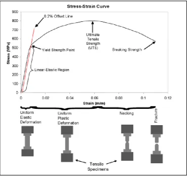
Figure 2.2: Changes plastic deformation of specimen.
Based on figure 2.2, the stress and strain initially increase with a direct relationship. This is the linear-elastic part of the bend and it demonstrates that no plastic twisting has happened. In this area of the bend, when the stress is decreased, the material will come back to its unique shape. In this direct district, the line complies with the relationship characterized as Hooke's Law where the proportion of stress to strain is a constant.
10 to the circumstance of a segment being extended with a tensile force. This modulus is of interest when it is important to register how much a pole or wire extends under a tensile load.
Yield quality is an extremely significance value for use in building basic outline subsequent to is the quality at which a metal or combination demonstrates huge plastic deformation. Since there is no clear point on the stress strain curve where elastic strain finishes and plastic strain starts, the yield quality is been that quality when a positive measure of plastic strain has happened. American engineering structural design, the yield quality is picked when 0.2 percent plastic strain has occurred, as showed on the designing stress strain chart of figure 2.2.
A definitive rigidity (UTS) is the maximum strength reached to in the engineering stress strain-curve. In the event that the example builds up a restricted abatement in cross-sectional area (normally called necking) appeared at figure 2.3.1. The engineering stress will diminish with further strain until fracture happens subsequent to the engineering stress is dictated by utilizing the first cross-sectional territory of the example. The more pliable a metal is, the more the example will neck before break and henceforth the more the lessening in the weight on the stress strain bend past the most maximum stress.
2.3 Modelling and Simulation