Software Engineering
Software Architecture
Mirza Rehenuma Tabassum
Architectural patterns
▪
Patterns are a means of representing, sharing and reusing
knowledge.
▪
An architectural pattern is a stylized description of good
design practice, which has been tried and tested in different
environments.
▪
Patterns should include information about when they are
and when the are not useful.
The Model-View-Controller
(MVC) pattern
Name MVC (Model-View-Controller)
Description Separates presentation and interaction from the system data. The system is structured into three logical components that interact with each other. The Model component manages the system data and associated operations on that data. The View component defines and manages how the data is presented to the user. The Controller component manages user interaction (e.g., key presses, mouse clicks, etc.) and passes these interactions to the View and the Model. See Figure 6.3.
When used Used when there are multiple ways to view and interact with data. Also used when the future requirements for interaction and presentation of data are unknown.
Advantages Allows the data to change independently of its representation and vice versa. Supports presentation of the same data in different ways with changes made in one representation shown in all of them.
Layered architecture
▪
Used to model the interfacing of sub-systems.
▪
Organises the system into a set of layers (or
abstract machines) each of which provide a set of
services.
▪
Supports the incremental development of
sub-systems in different layers. When a layer
interface changes, only the adjacent layer is
affected.
The Layered architecture
pattern
Name Layered architecture
Description Organizes the system into layers with related functionality associated with each layer. A layer provides services to the layer above it so the lowest-level layers represent core services that are likely to be used throughout the system. See Figure 6.6.
When used Used when building new facilities on top of existing systems; when the development is spread across several teams with each team responsibility for a layer of functionality; when there is a requirement for multi-level security.
Advantages Allows replacement of entire layers so long as the interface is maintained. Redundant facilities (e.g., authentication) can be provided in each layer to increase the dependability of the system.
Repository architecture
▪
Sub-systems must exchange data. This may be done in two
ways:
▪
Shared data is held in a central database or repository and may be
accessed by all sub-systems;
▪
Each sub-system maintains its own database and passes data
explicitly to other sub-systems.
▪
When large amounts of data are to be shared, the
The Repository pattern
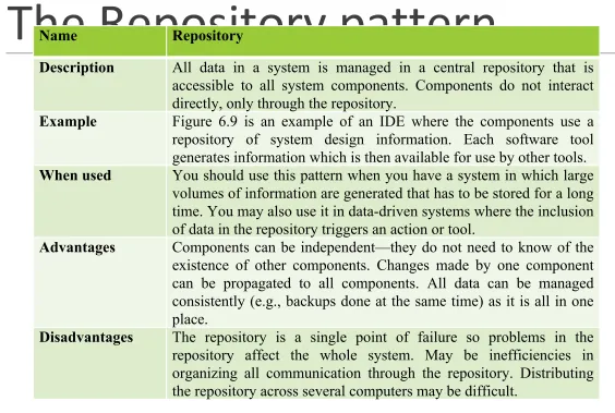
Name RepositoryDescription All data in a system is managed in a central repository that is accessible to all system components. Components do not interact directly, only through the repository.
Example Figure 6.9 is an example of an IDE where the components use a repository of system design information. Each software tool generates information which is then available for use by other tools.
When used You should use this pattern when you have a system in which large volumes of information are generated that has to be stored for a long time. You may also use it in data-driven systems where the inclusion of data in the repository triggers an action or tool.
Advantages Components can be independent—they do not need to know of the existence of other components. Changes made by one component can be propagated to all components. All data can be managed consistently (e.g., backups done at the same time) as it is all in one place.
[image:11.720.65.629.88.467.2]Client-server architecture
▪
Distributed system model which shows how data and
processing is distributed across a range of components.
▪
Can be implemented on a single computer.
▪
Set of stand-alone servers which provide specific services
such as printing, data management, etc.
▪
Set of clients which call on these services.
The Client–server pattern
Name Client-serverDescription In a client–server architecture, the functionality of the system is organized into services, with each service delivered from a separate server. Clients are users of these services and access servers to make use of them.
Example Figure 6.11 is an example of a film and video/DVD library organized as a client–server system.
When used Used when data in a shared database has to be accessed from a range of locations. Because servers can be replicated, may also be used when the load on a system is variable.
Advantages The principal advantage of this model is that servers can be distributed across a network. General functionality (e.g., a printing service) can be available to all clients and does not need to be implemented by all services.
Pipe and filter architecture
▪
Functional transformations process their inputs to
produce outputs.
▪
May be referred to as a pipe and filter model (as
in UNIX shell).
▪
Variants of this approach are very common. When
transformations are sequential, this is a batch
sequential model which is extensively used in
data processing systems.
The pipe and filter pattern
Name Pipe and filter
Description The processing of the data in a system is organized so that each processing component (filter) is discrete and carries out one type of data transformation. The data flows (as in a pipe) from one component to another for processing.
Example Figure 6.13 is an example of a pipe and filter system used for processing invoices.
When used Commonly used in data processing applications (both batch- and transaction-based) where inputs are processed in separate stages to generate related outputs.
Advantages Easy to understand and supports transformation reuse. Workflow style matches the structure of many business processes. Evolution by adding transformations is straightforward. Can be implemented as either a sequential or concurrent system.