Rochester Institute of Technology
RIT Scholar Works
Theses
Thesis/Dissertation Collections
7-1-2000
IDL-XML based information sharing model for
enterprise integration
Uanny Brens Garcia
Follow this and additional works at:
http://scholarworks.rit.edu/theses
This Thesis is brought to you for free and open access by the Thesis/Dissertation Collections at RIT Scholar Works. It has been accepted for inclusion in Theses by an authorized administrator of RIT Scholar Works. For more information, please [email protected].
Recommended Citation
IDL-XML Based Information Sharing Model for
Enterprise Integration
Uanny M. Brens Garcia
B.S. Pontificia Universidad Catolica Madre y Maestra
(Santiago, Dominican Republic 1998)
Thesis
submitted
in
partial
fulfillment
of
the
requirements for the degree of Master of Science in the
Department
of
Industrial
and
Manufacturing
Engineering in the Kate Gleason College of Engineering
of the Rochester Institute of Technology
KATE GLEASON COLLEGE OF ENGINEERING
ROCHESTER INSTITUTE OF TECHNOLOGY
ROCHESTER, NEW YORK
CERTIFICATE OF APPROVAL
MASTER OF SCIENCE DEGREE THESIS
The M. S. Degree Thesis of Uanny M. Brens Garcia
has been examined and approved by the thesis committee
as satisfactory for the thesis requirement for the
Master of Science degree.
Sudhakar Paidy, Ph.D.
Advisor
Permission granted
IDL-XML Based Information Sharing Model for Enterprise Integration
I, Vanny M. Brens Garcia, hereby grant permission to the Wallace Library of the Rochester
Institute of Technology to reproduce my thesis in whole or in part. Any reproduction will not be
for commercialllse or profit.
Dedication
To theBrens
family
andtheGarcia Family.They
havetaught meAcknowledgment
Throughout the time I have been working in this research study,
many people have assisted me. It is impossible to acknowledge them all, nevertheless, I would like to specifically thank the
following
individuals:Dr. Sudhakar
Paidy,
for all the time he dedicatedto myresearch workandfortheknowledge he has shared withmeinthelasttwo years. This thesis would not have been possible without yourhelp.
Dr. Wayne
Walter,
for his support and comments on my work. Ihopeyouenjoyed
being
amember ofmythesiscommittee.The
faculty
and staff of the Industrial andManufacturing
Engineering
Department,
notonly fortheiracademic supportandfeedbackon my work, but forall the advise given throughoutmy careeratRTF
Dr. James
Miller,
Dr. JasperShealy
and the officials at PUCMMfor setting up the program that allowed me to pursue thesis MasterofScience Degree.
To
Anne, Kevin,
Kaine,
Sri, Judith, Seau, Tara, Jenny,
Joy
andTom for
helping
me from thebeginning
of thethesis,
proofreading, giving me feedback and support. But mostly, for
Outline
Section
Page
1.
Abstract
92. Introduction 10
3. Computer Integrated
Manufacturing
143.1. Description andBackground 1 4
3.2. CIM Architecture: The National Institute of Standards and 14
Technology
CBVI ArchitectureModel 3.3.ManufacturingExecution SystemsAssociation 1 9
3.3.1. InformationSystem Architecture 1 9
3.3.2. Enterprise Resource
Planning
223.3.3.
Manufacturing
Execution Systems 243.3.4. Control Systems 29
3.4.
CORBA,
STEP,
DCOMandInformationSharing
303.4. 1 CORBA Definition 3 1
3.4. 1.2
Manufacturing
Execution SystemsandCORBA 323.4.2 XMLDefinition 33
3.4.2.1 XMLandEnterprise Communication 35
4. Relation between Information SystemsandEnterprise Wide Data 36 4.1 Relation between Information SystemsandEnterprise Wide Data 36
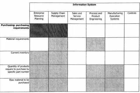
4.2 Information Systems andPurchaseInformation (Customer/Supplier 47
perspective)
5. Common ObjectRequestBroker Architecture 50
5.1 Distributed
Computing
andSoftware Architecture 505.2 CORBA
50
5.2.1 CORBA Components 52
5.3 Object Request Broker 54
5.3.1 DefinitionandHowit Works 54
5.3.2InteroperableObject Request Broker
56
5.3.3 Fault
Tolerance,
Object MigrationandGarbage Collection
57
Section
5.3.5 Remote Procedure Callsvs.
Object
Request Broker5.4
Interface
Definition Language5.5
Object
Management Architecture5.5.1 CORBA
Services5.5.2 CORBA Facilities
5.5.3 Application Objects
5.6 CORBA's New Features
5.7 BenefitsofCORBA
Page
61
62
63
64 65
66
66
68
6. Extensible
Markup
Language6.1 Standard Generalized
Markup
Language 6.1.1 Document Type Definition6.1.1 Elements 6.1.2 Attributes 6.1.3 Entities
6.2extensible
Markup
Language6.2.1 Document Type Definition in XML
6.2.2 Application
Processing
Interfaces for XML 6.2.3 Extensible Style Sheets6.2.4 XML Applications
6.3 XML Three Tier Architecture
7. JDL-XML Architecture for Enterprise Integration
8. References
9. Appendix
70 70 72 73 74 74
76 79 80 81 81
82
84
91
Tables
andFigures
Table Number
3.1 3.2 3.3 3.4 3.5 3.6Name
ofTable/Figure
Page
The NBS Model for
Manufacturing
Plants 18MESA Context Model 20
Relationship
between MESAarchitecture andCTMArchitecture 21 FlowofInformation(BetweenERP,
MES andControls)
24MEStoControls data flowpossibilities 25
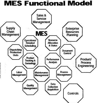
MES Functions 28
4.1 4.2 4.3 4.4 4.5 4.6 4.7 4.8 4.9 4.10 4.11
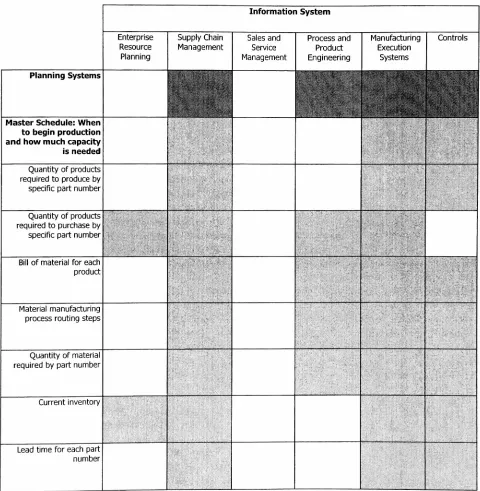
Information SystemsandenterpriseData Tables MasterSchedule
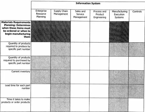
Materials Requirements
Planning
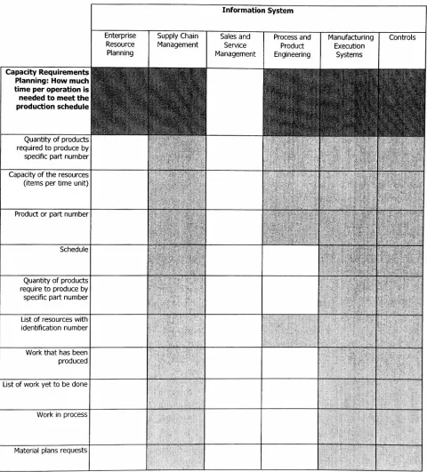
Capacity
RequirementsPlanning
Resource Acquisitions andPurchasing
Inventory
ManagementProduct/Engineering
Data Process ControlSystemsHuman Resources Management
Accounting
andFinanceSupplierPerspectiveofInformation Customer PerspectiveofInformation
38 39 40 41 42 43 44 45 46 48 49 5.1 5.2 5.3 5.4 5.5
CORBA Busmodel
Structureof aCORBA ORB
Remote ProcedureCallsvs. Object Request Broker
CORBA JLD Language Bindings The Object Management Architecture
51 52 61 62 63 6.1 6.2 6.3 6.4
XMLCode Example
XML's Tree Structure
Document Type Definition for
Inventory
.xml Three-Tier Architecture 78 79 80 82 7.1 7.2 7.3IDL-XMLArchitecture for Enterprise Integration
Interactionofthefour layersofTXA
Information
Sharing
Situationswith theIXA Model85
87
88
APPENDIX
MICOApplication. Examples if CORBA DDLcode
SGML document: Transcription andTagged Versionof aletter HTML document: Webpage
display,
and HTMLfile
1. Abstract
CJM is a mechanized approach to problem solving in an enterprise. Its basis is
intercommunication
between information systems, in order to provide faster and more effectivedecision makingprocess.These results
help
minimizehumanerror, improveoverallproductivityand guarantee customersatisfaction.
Most enterprises or corporations started
implementing
integrationby
adopting automatedsolutionsinaparticularprocess,
department,
orarea,in isolation from therest ofthe physical orintelligent process resulting in the
incapability
for systems and equipment to share informationwitheach other andwith other computer systems.The goal inamanufacturingenvironmentis to
havea setof systems that will interact seamlesslywith eachother within aheterogeneous object
framework overcomingthemany barriers
(language,
platforms, andeven physicallocation)
thatdonot grantinformationsharing.
This study identifiesthedataneeds of severalinformation systems of acorporation andproposes a conceptual model to improve the information sharing process and thus Computer Integrated Manufacturing.
The architecture proposed in this workprovides a methodology for datastorage, data retrieval,
anddata processing inordertoprovideintegrationattheenterpriselevel. There are four layersof
interaction in the proposed IXA architecture. The name TXA (DDL
-XML Architecture for Enterprise
Integration)
is derived fromthe standards and technologies used to define the layersandcorresponding functionsof eachlayer. The first layeraddressesthesystems andapplications
responsiblefor datamanipulation. Thesecondlayerprovides theinterface definitionstofacilitate
theinteractionbetweenthe applications onthefirst layer. The thirdlayer is where datawouldbe
structured using XML to be stored and the fourth layer is a central repository and its database
2.
Introduction:
Since
theirintroduction,
computers(andcomputer-assisted applications) have been developed tobetter
servehumans.
They
have been widely used throughout manufacturing environments. In1953,
General Electric was one of the first organizations to use computers in financial applications. One yearlater,
numerical controlmachines wereintroduced;
and then in1955,
thefirst
automatically
programmed tool started what we now know as Computer-AidedManufacturing
- CAM(Shrensker,
1991).Afterthe
1950's,
computers havebecomefaster,
smaller andmore affordable.Thisresultedin numerous computer applicationsfor different manufacturingtasks.Computer Aided Designwas made publicintheearly 1960'sandotherCAMsoftwarelike Materials RequirementPlanning
(MRP)
hadtheirfirstappearanceintheearly 1970's(Robinson,
2000). MRPisa software developedtohelp
withscheduling tasks, but it hasturnedouttohave relativelypoorperformance
(Robinson,
2000). Thenext generation ofComputer IntegratedManufacturing
(CIM)
wasManufacturing
ResourcePlanning,
orMRPIJ. Itwas withthese twoapplications(MRP,
andMRPIT)
that the termComputer IntegratedManufacturing
was coined. Dr. Joseph Harrington firstusedthe termin1974,
but itwas not until 1981 thatit became widelyused, probablyafterMRPandMRPIJbecamepopular(Shrensker,
1991).Since
1981,
computershave evolvedfromhaving
acouple ofhundredsofkilobytes ofmemory to several gigabytes of memory(among
other resource enhancements), making them very powerful and enabling manycomputer-aided systems to be developed. Forexample, computer-aided engineering, computer-aided systems for manufacturing process planning, shopscheduling,
inventory
control, decision support, human resources applications, and diverse financial applications were making common appearances in 1980s within manufacturingenvironments
(Shrensker,
1991).Today,
applications are run notonlyondedicated systems,but arerun across multiple computers andacrossnetworks.They
areas complexasmainframes orassmallas sensors andlogic controllers;and themanufacturing floor includesvaried computerized devices such as robots and robotic cells, computer numerical controlled machines, automated decisionsupportsystems,etc.
Computer Integrated
Manufacturing
comprises not only the product making activities such as engineering and manufacturing but all the disciplines within an enterpriseincluding
marketing, sales,distribution, finance,
human resources, and general office administrations.According
to Shrensker: "Afully
integrated CEVI system involvesthedesign,
development,
or application ofeach of the systems in such a manner that the output of one system serves as the
input
of another"(Shrensker,
1991). Inotherwords, Computer IntegratedManufacturing
isanenterprise-wide effort, where the data would
"flow"
from one place to another and
improve
thebusiness
process.
The
Society
ofManufacturing
Engineers definesCIM
as theintegration
of the totalmanufacturing enterprise through the use of
integrated
systems anddata
communicationscoupled with new managerial philosophiesthat
improve
organizational and personnelefficiency
1980's
the general concept ofComputer AidedManufacturing
leadto what is known asIslands
ofAutomation. Computer
IntegratedManufacturing's
aim was to integrate theseindependent
systems(Vernadat,
1996). Bartlett explains that CIMis
concerned with providing computer assistance and control, along withhigh-level
integrated
automation at all levels of themanufacturing
industries,
by linking
islands
of automation into a distributed processing system(Bartlett,
1995).
Many
companies in the United States and most companies indeveloping
countries still handle theoutput of automated systems withmanual techniques.Thereremains a gap between whentheinformation is needed and when itcan be delivered (this is based on the time it takes to collect
the data manually). The solution should be a responsive, adaptable, and reliable computer systemsthatsupportstheCIMconceptthroughout theenterprise
(Attran,
1995).The basisofComputer Integrated
Manufacturing
is intercommunication betweentheinformation systems processorstofacilitateafasterand moreefficientdecision makingprocess. Processorsat all decision makingandsupervisory levelsof anenterprise needtheabilityto gatherthe dataandtrack the status of operations necessary to assess manufacturing efficiency
(Snyder,
1997). Specialized software, plustheintegration ofdatasystems, providesthe typical firmwith a muchmorerobust systemthanhas beenpossible inthepast
(Oleson,
1999).The problem facedwith CIM is nicely described
by
Bubsy,
when heexplains that the principalcomputer applications in amanufacturing company are large and substantially isolated systems bought from differentsuppliers andoriginallyspecifiedtobe
freestanding
ofothersystems.They
run on different types ofmachines, use different operating systems, and
they
are generally built ondifferent databasemanagementsystems(Bubsy,
1992).But
Bubsy
is nottheonlyauthorconcerned withthepoorintegrationof systemsin an enterprise.Associations such as the
Society
ofManufacturing
Engineers(SME),
theManufacturing
Executions Systems Association (MESA
International),
and companies likeBoeing
devote their time to research thecurrenttechnology
andtodevelop
newtechnology
that would improve theintegration intheenterprise.
Many
researches havealso expressedthe need forapplications andinformation systems to have seamless communication in order to achieve full enterprise integration
(Allegri, 1989; Hardwick,
1996;
McClellan, 1997; Adelsberger, 1995;
Scharpf, 1999;
Singh, 1996;
andSvenson,
1993).The importance of information and data sharing through the manufacturing
facility
lies
in thefact that accurate and consistent information is crucial to make
business decisions
and processimprovement
(Bhatt,
2000). Since the last quarter of the TwentiethCentury,
automation has forced manufacturing companies todevelop
more and more sophisticated computer communication strategies in ordertoguarantee theirmaximumbenefit to thecompany
(Bartlett,
1995). The availability of better
data,
advances in analyticaltechniques,
and everimproving
communications enhance a company's ability to make more complex and effective
decisions,
andthusmaintains acompany'scompetitiveedge(Metz,
1998).
Information
is
notonly neededinan accuratemanner,it is
also neededin atimely
fashion.
Real
real-time, accurate, reliable,
flexible,
and modifiable to interfacedirectly
with thedepartments
thathave
theresponsibility
of controlling the processes, and in predicting the results of theiractions and
decisions
(Rathmill,
1998). InformationSystems
(IS)
and InformationTechnology
solutions, throughcommunication networks and
database
systems, enableorganizationstocreate and sustain process improvement(Bhatt,
2000). The tools exist todevelop
technologies and toacquire
integration
throughout the enterprise.Today,
most information systems and systemsintegration
vendors work toward thedevelopment
of an enterprise-wide system that contains a centraldatabase
compiled from the operations of multiple machines and multiple processes(Snyder,
1997).Companies
like AdasoftGroup
saythatafactory
mustbe consideredas awhole,where the systems for administration, management, maintenance control, follow up and command cannotbe independent (Adasoft
Group,
2000).In orderfor manufacturing applications to communicate efficiently, an information structure is needed. Although the nature ofthe information is diverse in manufacturing environments, this
information is
frequently
commontootherapplications(Busby, 1992; Hardwick,
1996). Thereistheneed of structuredinformation sharingmethods and models thatwould allow datatobeused
by
the different applications and systems.Bubsy
makes the point that if no mechanisms are introduced to specifically regulate the information sharing process, there is a risk ofinconsistency,
duplicationand omission ofdata(Bubsy,
1992).The Computer Integrated
Manufacturing
Architecture (CIMArchitecture)
explainedinfollowing
sections gives aschemaofhow information flows in amanufacturingenvironment. In the same
way, the
Manufacturing
Execution Systems Association's Context Model (MESA ContextModel)
defines the six information systems relevant to an enterprise and relates these systems according to the data shared. These two architectures share many of the basic concepts ofinformation flowand we present adiagramthatrelatesthese twoarchitectures.
Furthermore,
the relationship betweenthe dataof an enterprise and the six information systems(Enterprise Resource
Planning,
Supply
ChainManagement,
Sales and ServiceManagement,
ProductandProcess
Engineering,
Manufacturing
Execution Systems andControls)
is graphicallyshown in tables. These tables have the objective of reinforcing the concept that
information
iscommontodifferentdepartments and systemsof an enterprise.
Thus,
agoodinformationsharing
architectureshouldbe implementedtoimprovethedata sharingprocess.The objective of this thesis work is to propose an architecture thatprovides a
methodology
of data storage, dataretrieval, and data processing in order to provideintegration
at the enterprise level. The modeldeveloped itscalledIDL-XMLArchitecture
for EnterpriseIntegration
(IXA for Enterprise Integration). There are four layers of interaction in the proposed TXA architecture.The name IXA Enterprise Integration is derived from the standards and technologies used to
definethe layersandcorresponding
functions
ofeachlayer.The two technologies used to
develop
the IXA are theCommon
ObjectRequest Broker
Architecture
(CORBA),
and the extensibleMarkup
Language (XML).CORBA is
a set ofstandards that establishes the
interfaces
and parametersfor
applications tointeract
with one another. One ofCORBA'
The
XML
is amarkup
language thatdefines how datawouldbe structure; itgives thecontrol ofhow
thedatawouldbe displayedand manipulatedto theapplicationusingthe data.Therefore,
CORBA and XML are the basis of theIDL-XML
Architecture for EnterpriseIntegration
proposedinthiswork. Thepurpose oftheIXA modelis tofacilitatethe informationstorage, retrieval, and processing of information across the enterprise. Since data are collected and utilized from systems of different platforms,
languages,
applications, allocations, etc., itmakes the process of information access, utilization, and sharing difficult.
By
using a centralrepository, or common databasestorage,therewouldbe aplace forallhardwareand/orsoftware inthecorporationtostore andretrieveinformationwhenneeded. Interaction betweenthe central
repository and the information system would be controlled and manipulated
by
layers ofsoftware that would act as an intermediate access manager, and would restrict the information sharing and access process. The concept is to
develop
interface layers (based on CORBA andXML)
betweenthesystems andthecentral repository.The IXA model would provide the means for communication among information systems via
CORBA. It structures the data using XML
hierarchy
to allow a better navigation throughdigitally
represented documents andinformation,
and provides an API interface(using
CORBA'3.
Computer
Integrated
Manufacturing
3.1
Description
andBackgroundComputer Integrated
Manufacturing
is a modernmanufacturing
paradigm. Itaims at integrationof man and machine activities
by
facilitating
communication, cooperation and coordination ofthevarious
technical,
administrative, and supportfunctions
ofamanufacturingcompany. It aimsto achieve this
by
means of information and communication technologies, from design toproduction planning, from control to manufacturing and shipping
(Vernadat,
1996). Theimportance
of data communications is further emphasizedby
theSociety
ofManufacturing
Engineers;
SME states that data communicationimproves
organizational and personnelefficiency inacorporation.
Usually,
solutionsdevelopedtoimprove an areainvolveasingleautomationtool.This conceptis known as "IslandsofAutomation" and itwas themost prevailing model ofcomputerintegratedmanufacturing in the 1980's. As a result of this, automated solutions are implemented in a particular process, department or area, in isolation from the rest ofthe physical or intelligent
process.
However,
thekey
is to approach enterprise's problems with an integrated set oftoolsthat will consider and fix all the problems at once and improve over all production
(Vernadat,
1996). Thisiswhatis knownasComputer Integrated
Manufacturing
(CIM).Computer Integrated
Manufacturing (CIM)
became thesolutionforanintegratedset of problems recognizedby
companies. TheSociety
ofManufacturing
Engineers(SME)
defines CIM as theinteraction ofthe total manufacturingenterprise through theuse ofintegrated systems and data
communications coupled with new managerial philosophies that improve organizational and personnel efficiency
(Rehg,
1994). Inotherwords, Computer Integrated Manufacturing'sgoal isto integrate man and machine activities
by facilitating
communication, cooperation andcoordination ofthe various technical, administrative and support functions of a manufacturing
company,
by
means ofinformation and communication technologies betweendesign,
planning,control and shipping (Vernadad. 1996).
Thus,
Computer IntegratedManufacturing
is amechanized approach to problem solving in an enterprise. Its basis is
intercommunication
between information systemsto providefaster and more effectivedecision making process, and
as a result minimizes human error, improves overall productivity and guarantees customer satisfaction.
3.2 CIMArchitecture
Information flow in an enterprise is crucial to determine the design and
implementation
of anintegration system.
By
referring to the National Institute of Standard andTechnology
(NIST)
model for manufacturing plants, we notice the
hierarchy
of thedifferent
activities within acompany. If we follow this model to structure the
information
flow,
so that eachlayer
communicates only with the layerdirectly
above ordirectly
below,
thesharing
andflow
oftheThe
NIST developed
theShop
Floor Production Model(SFPM)
as ageneric architecturefor
realtime production control. It is based on a tree-shaped
hierarchy
with command/feedback controlstructure, where the control processes are
isolated
by
function
and communicate via standardinterfaces (Jones
et al, 1986). This approach ensures that the size,functionality
and complexity ofindividual
control modules are limited. Each of the modules in this architecture has to bedesigned
in a way that humans can comprehend and interact with them.Also,
hierarchicalapproach reducesthe complexityofthecontrol problems because thecontrol resides at the next higher level and the decisions are made at the lowest possible level
(Jones, 1986;
RathmiH,
1988).
Every
control module decomposes its currentinput
command from its supervisor intoprocedures to be executed at that
level,
subcommands to be issued to one or more lower modules, andstatusfeedbacksentbackto thehigher level(Jones,
1986).The SFPM
hierarchy
has been developed basedoncontrolmodules,each of whichis determinedby
its planning horizon. The planing horizon is the period of time over which the module isresponsiblefor planingandupdating localgoals. Themainprinciplebehind SFMParchitecture is
that processing becomes more and more time critical at the lower levels ofthe
hierarchy;
thus,
theplaning horizon becomes smaller atthe lower levels and the processing becomes more time critical.(Rathmill,
1988).Thedifferent levels oftheNIST CEVIS architecture are:
Level 5
-Facility
Control System (Alsocalled:Plantlevel,
EnterpriseLevel,
Factory
Level):This is thehighest levelof control andits implemented in thefront office.The planning horizon
can be anywhere from several months to years. Its responsibility is for overall planing and
execution; itmanagestheproduction offinishedproducts
by
controlling job shops. Its decisionsare strategic innature,and ofgreatimportance forthecorporation. This levelgives support to the CIM system through the integration of orders, sales
data,
manufacturing, shipment, andinvoicing.
Factory
level is broken down insubsystemsthatfall intothreemajorfunctional areas:Manufacturing
engineering:Herearethefunctionstypically
carriedoutwithhumaninvolvement
via userdata interfaces (i.e. CAD/CAM).Information management: Provides user data interfaces to support necessary administrative or
businessmanagement functions (i.e. cost estimation,job cost accounting,
inventory
accounting,etc).
Level 4
-Shop
Control System
(AlsocalledFactory level)
The
shop
control system manages the production of parts and part's componentby
controllingwork centers. Itcoordinates theproduction and support activitiesthat are carriedout
by
the cell controllers at the nextlower level. This levelis
responsible for coordinating the production and supportjobs
ontheshop
floor,
anditis
also responsible forallocationofresourcesto thosejobs.However,
the main function of this level is to schedule production and provide managementinformation
by
monitoring andsupervisingthelower levels ofcontrol.The
decisions
ofthe shopcontrol system areboth strategic and operational, andit has aplaninghorizonthatcouldbeanywherefromseveral weeks toseveral months.
Twomajor components ofthislevelare:
Taskmanager: Schedules job orders, equipment maintenance, and shop support services; it also
tracksequipmentutilization, schedules preventive maintenance, andmaterial transferequipment
inthefactory.
Resource Management: It allocates workstations, buffer storage areas, trays, tooling, and
materialstocelllevelcontrol systems forparticular productionjobs. Italso monitorsand updates
levels for all raw stock, work in process, cutting tools, and replacement parts inventories
necessarytorunthefactory.
Level 3- Cell Control System (Alsocalled: Area
Level,
andCell Level):Cell control system's responsibility is the sequencing of batch jobs of similar parts though
workstations and supervising other support services, for example material
handling,
or calibration. This level is in charge oftasks like goods storage and retrieval, and transportationandmanufacturingof parts. Itdirectsand coordinatestheshop floorproductionprocess,butalso,
coordinates production flow among various stations and integrates individual stations into an automated system. Modules within the work cell level perform task
decomposition,
analyze resource requirements, prepare requisitions, report job progress and system status to the shopcontrol system, makedynamic batch routing
decisions,
and schedule operations. Also itdecodes
the order received from the higher level into more elementarymanufacturing
jobs so thatmachinecells can process theinformation.
The planning horizoncan be anywhere from several hoursto several weeks, andthe
decisions
it takesareoperational innature.Level 2 - Workstation Control System (Alsocalled:
Work-center
Level,
orStationLevel):
Workstation level coordinatesanddirectsthe activities ofsmall,
integrated
physical groupingsofThis level
is in charge ofconverting theinput from
lowerlevels
to output commands, since itexchanges
data
withthe scheduling, productionplanning
andmaterialhandling
activities and at thesametimewiththecontrollers, actuators, and sensorsfromthe lower levels.At the
Workstation
Control System the planning horizon can be anywhere between severalminutestoseveral
hours,
andthenatureofthedecisionsis
operational.Level 1-
Equipment
Control System (Alsocalled Machine
level,
orEquipment level):Here is where basic interface with plant floor equipment takes place. The main tasks of the Equipment Control System areto translate thecommands fromthe workstation controllerinto a
sequence of simpletasksthatcanbeunderstood
by
thevendor supplied controllerandto monitor theexecutionofthose tasksviathevarious sensors attachedto thehardware.The equipment control system acts as the interface between the workstation control system
above and the vendor supplied controller on the hardware under its control.
Therefore,
the informationgathered comes fromtheexecution ofthejobattheshop floor. The planning horizonmay beanywherebetweenseveral millisecondstoseveralminutes.
Level0- Floor level:
This level is comprised of all the devices that perform direct action on the manufacturing
process,i.e. sensors,and actuators. Theirtaskistocollectinformationrelated to theexecutionof the job at the shop
floor,
and to carry out the commands in order tokeep
the manufacturingprocess running.
They
have the smallest planning horizon and fastest processing and decisionLevel5
FacilityLevel
Manufacturing
PlantLevel 4
Shop
LevelMachine
Shop
Assembly
Shop
Level 3
Cell Level Virtual
Celll
Virtual
Celln
Level 2
Work Station Level
Milling
WorkStationInspection
Work Station
WorkStation
n
Level 1
Equipment Level
Robot
Milling
Machine
Robot Inspection
Machine
Robot Part
Buffer
Level0
FloorLevel
Sensors &
Actuators
Sensors &
Actuators
Sensors &
Actuators
Sensors &
Actuators
Sensors &
Actuators
Sensors &
[image:19.553.26.516.147.509.2]Actuators
3.3
Manufacturing
Execution
Systems Association
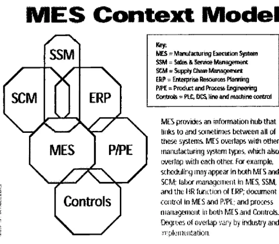
3.3.1 MESA Information
SystemsArchitecture:
The
Manufacturing
Execution Systems Association International (MESAInternational)
hasdeveloped
anEnterprise
Information SystemArchitecture
orContext Model. This modeldepicts
the relation
between
the major manufacturing software systems categories. Each system(Enterprise
ResourcePlanning,
Manufacturing
ExecutionSystem,
Supply
ChainManagement,
Sales and ServiceManagement,
Product andProcessEngineering,
andControls)
is the groupingof different applications and functions of an enterprise.
Thus,
an enterprise needs somefunctionality
from each ofthese systems in order to achieve success (MESA 1997). The scope and utilizationofthesystems willdepend onthetype ofenterprise and manufacturingprocess it has (if it is a serviceprovider, adiscrete manufacturing,continuous,batch,
or assembly process,maketo order,etc).
MESAgivesthe
following
definitions foreachsystem:Enterprise Resource
Planning
(ERP): Consists ofthose systems that providefinancial,
ordermanagement, production, and material planning. ERP is a manufacturing information system
whose focusgoesbeyond
inventory
control anddistributedmanagement activities. Its purposeis tobring
together areas like engineering,finance,
human resources, project management, etc.Moreover,
it can be consider as a medium to achieve the connection via computer systems, between the different subsets of manufacturing systems. ERP is more concerned aboutautomationand computer-aidedprocessesofthe
integration,
andhence is theinformationsystem thatautomates core activities of an enterprise.Sales and Service Management (SSM): Comprises software to support the sales activities, as
well as after sales service. It takes care of sales automation, product configurations, services
quoting, productreturn, andso forth.
Supply
Chain Management (SCM): Includes functions asforecasting,
distribution
andlogistics,
transportation management, e-commerce, and advanced planning systems.Supply
chain management is the logical customer-focused progression of physical
distribution
and logistics management, it incorporates the material flow functions of receiving raw material orsub assemblies, manufacturing, distribution and
delivering
(Metz,
1999). Itis
a network of facilities and distribution options that performs the functions of procurement of materials,transformation ofthese materialsinto intermediateand finished products, andthe
distribution
of thesefinishedproductstocustomers(Ganeshan,
2000).Product and Process
Engineering
(P&PE): Includes computer aideddesigns
andmanufacturing, process modeling, and product datamanagement. P&PE
keeps
track ofthelife
cycle for both the products andthe process. Itis
the tool thatcaptures thelearning
that goes on with the product and process. The system collects datafrom
the process and turns itinto
information about the process. It then analyzes theinformation
anddetermines
what course ofManufacturing
Execution
Systems(MES):
The Information Systemthatprovidesinformation
to
effectively
execute operations in order to meet business goals.Using
current and accuratedata,
MES guides,initiates,
responds toand reports on plant activities astheoccur. The resultingrapid response to change gives as an output effective plant operations and processes. MES
provides mission-criticalinformation about production activities acrosstheenterprise and supply
chain via
bi-directional
communicationsControls:
Systemsandcomputerizedprocess controls designedtomonitorand adjust theway inwhich products are
being
manufactured. Control systems are necessary to collect and processinformation about certain tasks and attributes in order to maintain the manufacturing process
running in accordancetowhat is expected and to makethe appropriate decisions when required
(Vaughn,
1967).MES
Context
Model
Key; MES
-Martir stujrnsg ixmnakmSystem SSM=Sa"ei& Servicehtenaganssrat
ssm-%ijppt'fChamManagement EBfTsEluapfHaStesourcfflp!amg
PK-=PrcductandPtceasiEjigiraerBg ContKite
-ftZ, MStineand imtitim tat&nA
P/PE
\s^.
Controls
/
MESprovidos an snfamationhubthat Sinks loand sometimesbetweenallof thesesystems.MtSoverlapswishother maiusfacturtngsjsIbibIjpes,winchalso
overlapwith eachother.Forexample,
sctxctulitxjmayappearin bahMESami
SCM;tabormanagBmBfflinMES, SSM
aniltheHRfunctionofERi*document controlin-MESandP/Fl;andproems managementin both MESandControls. Degressofo'/alap>yby industryarid
[image:21.553.119.403.365.613.2]implementation.
After
a closelook
atboth
theMESA Information Context Model andtheNIST CIM Architecturemodel, a
similarity
infunctionality
canbe
noted. Each model describes the relation betweensystems and applications within a
manufacturing
environment; both depict similar type ofimplementation
intheirrespective model.The tasks or
functions
of an enterprise are classified according to similarity of informationshared, type of resources used, and the significance ofthe output with other functions in the enterprise. The CIMmodelpositions theactivitiesinvolved in job shopproduction
hierarchically
with respect to management activity and area of responsibility
(Vernadat,
1996). The MESA model relatestheactivities on anenterpriseaccordingtotheinformationshared.Similarities
between
the twomodels confirmtheflowofinformationwithin an enterprise, whereall aspects of manufacturing and front office functions have to be considered, but where
communication in all directions among all systems is not possible. This communication
incompatibility
is due tothe different nature oftheinteracting
functions,
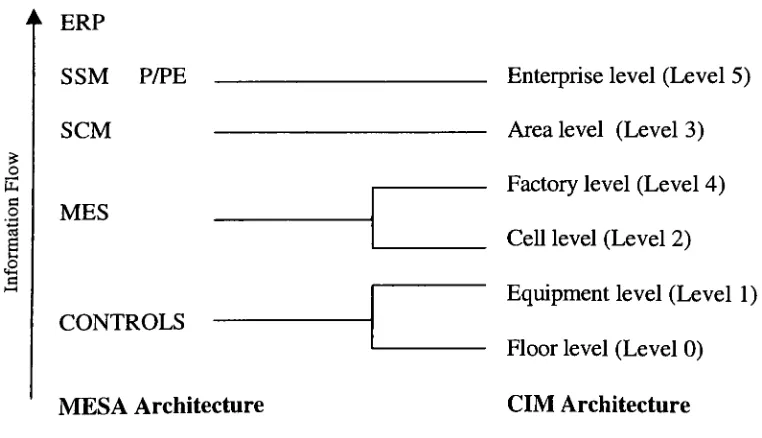
and is the cause ofthe emerging manufacturing integration systems with object oriented functions and distributed computing.Based on the similarity of information
flow,
we could map the MESA system functions to the CIMS architecture. This would giveus an ideaofthe area ofapplication each function on the MESAsystem addresses.o E a o
ERP
SSM P/PE
SCM
MES
CONTROLS
MESA Architecture
Enterprise level (Level
5)
Arealevel (Level
3)
Factory
level (Level4)
Cell level (Level
2)
Equipmentlevel (Level
1)
Floor level (Level
0)
[image:22.553.57.438.410.629.2]CIM
Architecture
The components ofthe Floor and
Equipment level
(sensors,
actuators and controllers) monitor,regulate and manipulate,
in
adirect
manner, the manufacturing operation. The ControlSystem
would manage these
devices,
and would share the necessary information from the process withtheMES.
The Cell level needs the scheduling and production
planning
information inorder to handle theproper
instructions
to the lower levels. TheShop
Control Systemis
where that productionplanning
is processed.Moreover,
MESis
the "virtual supervisor". It looks over the controllers and actuators to make sure the process is running accordingly; it prepares the scheduling andkeeps
production records.While SCM consists of
forecasting,
logistics and advancedplanning; the AreaLevel makes thesequence of jobs. Coordinates production low among different entities of the enterprise, the retrieval ofstoragematerial, andthetransportationofparts.
The Enterprise level is concerned with the overall process, without
looking
at the small details.Since SSM and P&PE needto look atthe process, product, market, sales and suppliers, it also
needsanoverallview oftheenterprise.
ERP,
as stated in the next pages, comprises all departments and functions. It takes into accountinformation fromeachofthedepartmentsandeachoftheinformationsystems.
3.3.2.
Enterprise
Resource Planning:
According
toChang
(Chang, 1998),
Manufacturing
System is an organization that comprises several interrelated manufacturing subsets. Its objective is to interface with outside productionfunctionsinordertooptimizethe total productivityperformance ofthe system(production
time,
costs, and machine utilization). The activities of these subsets include
design,
planning,manufacturing, and control. These subsets are also connected with production
functions
outside the system,such as: accounting, marketing,financing,
and personnel.Enterprise Resource
Planning (ERP)
is a manufacturing system whose focus goesbeyond
inventory
control anddistributedmanagement activities. ERPcanbe considered as a mediumto achieve the connection, via computer systems, between the different subsets of manufacturing.Production decisions affect and are affected
by
areas like engineering, accounting,human
resource, marketing, and sales, and in order tomake better
decisions,
corporations have to take into account the impact those areas have.By
making available thenecessary
information,
ERPsystemsassureanenhanceddecisions makingprocess
(Hicks,
1995).It is worth noting that ERP
is
the result ofthe evolution ofothermanufacturing
systems, moreparticularly, Materials Requirement
Planning
(MRP)
andManufacturing
Resource
Planning
(MRP II). MRP systems translated the master schedule
built
for the enditems into
time-phasesnet requirements for the sub-assemblies, components and raw materials planning, and procurement. MRP II evolved as an extension of MRP to
shop floor
anddistribution
management activities. ERP is the"natural"
engineering,
finance,
human resource, project management and others were added. The firsts to coin thisterm,
ERP,
weretheGartnerGroup
ofStamford,
Connecticut(Hicks,
1995).Althoughsome authorsdescribe ERP as a collection of softwareprograms, andothersas a set of
applications, the common concept is that ERP system integrates various enterprise
functions,
automating
front
officedepartments'
functions,
andmaking informationavailablethroughout the corporation."ERP
attempts to integrate alldepartments
and functions across acompany onto a single computer system thatcan serve all those different departments'particular
needs"
(Koch,
1999).
Since integration began as a set of Islands of Integration (where different software programs
serve thepurposes ofthedifferentdepartments and operationswithin acorporation) each works
independently
fromthe others, andthusERP seeks to unifythesesystems. ERP aims to create a computer environment where all systems of an enterprise or corporation share informationbetweeneachother; allapplications withinthesystemhaveaccesstoacommon
database,
giving as result a process more effective and less prone to error. ERP software defines a specific application for a specific operation (i.e. payroll, customer order, scheduling, and product request...), "everyoneinthecompanyseesthesame computer screenandhasaccessto the single
database that holds the customer's new
order"
(Koch,
1999). ERP leans on client/serverdistributed architecture, RDBMS (relational database management systems) and object oriented programmingtechnology. The information is accessible
by
who ever need it. "ERPobjective isto take information from every corporate
function,
it is a tool that assists employees and managerstoplan, monitor,and controltheentirebusiness"(Cambashi,
1999).The main goal of ERP systems is to allow the corporation to gain control of their dispersed information sources, incompatible computer systems and multilingual work force.
Also,
ERPprovides:
Information access: features and functions that deliver
fast,
accurate information to users toenablethem tomakesounddecisions.
Productivity: architecture and tools that increases worker productivity
by
automating processes andtasks.Freedom of choice (open architecture): support for
leading
systems platforms, relationaldatabases,
andoperating systems.Flexibility: tools that areeasy to use, and applications that areeasy tocustomize andeasy to upgrade.
With ERP companies will see integration of enterprise wide information andthe elimination of redundantdata. ERP softwareis designedto model and automate manyofthebasicprocesses of a company, from finance to the shop
floor,
with the goal ofintegrating
information
across the3.3.3
Manufacturing
Execution
Systems
MESA International
gives thefollowing
definition
ofMES,
which is widely accepted through outthedifferent
MES vendors and enterprises:"Manufacturing
Execution Systems deliver information enabling the optimization of production activities from orderlaunchto finishedgoods.Using
currentand accurate data,MES guides, initiates, respondstoand reports on plant activities astheoccur.The resulting rapidresponse tochangingconditions,coupledwith afocus onreducing non-value-addedactivities,driveseffective plantoperations and processes.MES improvesthereturnon operational assets as well as on-time delivery,inventory
turns, gross margin, and cash flow performance. MES provides mission-critical information about production activities across the enterprise and supply chain via bi-directionalcommunications"
(Davis, 1999;mesa.org).
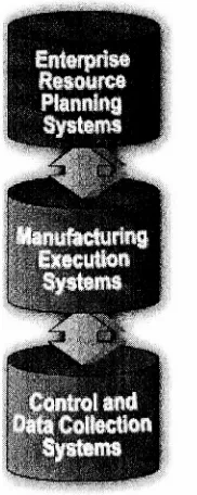
Implementation ofERP systemsinvolvesmorethan the top-level activities ofacorporation.But
in order for a ERP system to be of benefit for a corporation, the manufacturing part of the
corporation,(theplant
floor,
production,andqualitydata)
mustbe integratedto thesystem. Here is whereMEScomestoplay.MES is the link between controls and ERP.
According
to AdasoftGroup,
"Afactory
must beconsidered as a whole. The systems for administration, management, maintenance control,
follow up and commandcannotbe
independent"
(www.adasoft.com). MES works as the bridge between frontofficeaccountingand the
factory
supervisorycontrol systems andproduct, andits the partoftheenterprise'sinformationsystems thatresidesontheplantfloor.Enterprise Rssowe*
Planning
Systems
,. ring Execution x Systems,
Controlmd
[image:25.554.234.325.379.607.2]I Collection
Systems
Figure 3.4: Flowofinformation (Raytheon AutomatedSystems;
http://www.esys.com/rec/autosys/sub_erp.htm)
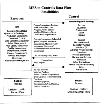
MES provides basic interface between planning and execution systems
(MESA,
1997). This
factors
on workbeing
performed. But also,interaction
between MES and the Control Systemis
very
important:
MES is in
charge ofthe overallflow
ofthe product or process. The specificperformance of a piece ofequipment, or an operator,
is
not as important to the MES as to a controller.That is
why, MES' central repositorycollects data from various locations within thefactory,
rather thanfrom
a particular area.The MES
downloads instructions about the processoperators and machines requiredtocarryoutthemanufacturingoperations(See figure 3.5).
Akin
ERP,
MES is
a product ofthe evolution ofMRP andMRP II. MESis
viewedby
some as an enhanced version of the functions performedby
MRP II(MESA,
1997). The firstmanufacturingapplications occurred as a
by-product
ofthecomputerizationofaccounting,morespecific,
inventory
accounting. MRP IIintroduced
a closed-loop manufacturing system, emphasizedin
material planning. But MESimproved
the coordination of cross-functional activities, thedevelopment
of a realistic schedule, and mostimportant,
the development ofapplications with the capability to monitor the floor activities and to continuously analyze
activitiesinordertoberesponsiveto eventsas
they
occur.MES
to
Controls Data Flow
Possibilities
Execution Control MES Resource Alloc/Status OperationScheduling ProductionDispatching Document Control Data Collection/Acquisition Labor Management WIPStatus/Traceability QualityManagement Performance Analysis Process Management ProductTracking&Genealogy Maintenance Management
Process Instructions:Recipes,
WorkInstructions,Part
Programs,OrderSpecific,
MachineUtilization,Work CertificationRequirements
Operator Instructions: Scheduled (predefined)and preventive maintenance,MaterialSafety
Instructions(documents) Machine Operation Instructions
(documents)
Drill Down(Inquiries)Status
Process Status Batch Reports Focus: Product Decision Location: FactoryPlant
Ad Hoc Inquiries MaterialsAnalysis
Events: Time/Date/log/Alarms Data CollectedformMonitoring
Functions: ProcessEquipment,
Environment, Labor, Material,
Product Parameters.
MonitoringandSensing
Process Equipment Environment Labor Material Control Machine Control RegulatoryControl Real-time QC Advance Process Control
Operations ProcessSequencing MachineandProcess
Interaction LaborInstructions Human MachineInterfacing
Safety Maintenance
Focus: Process
DecisionLocation:
[image:26.553.62.452.278.679.2]Shop
Floor/PlantFloorThe
primary
goal of any manufacturing execution system is to accelerate the flow of workthroughout the plant floor. MES provides an electronic network forperformance improvement
because
it can monitor production in real-time, giving accurate and recent information to solve situations and avoid production delays or quality problems(MESA,
1997).Otherwise,
production control personnel and supervisors may takemany hours a
day
toresearch the current status of all thejobs
on the floor in order to solve a problem or todevelop
a work schedule(Davis,
1999).MES
delivers information thatenables the optimization ofproduction activitiesfrom
orderlaunch
to finished goods. Thus MES provides critical information about theproduction acrossthe enterprise
(MESA,
1997).MES providesavirtual production
keeper,
supervisor, quality control and material requesters. Itdumps the necessary data and information into a common database within a computerized system that gives backthe status oftheproduction and theplant floor. This system can be seen as avirtual counterpart ofthephysicalprocess,
by
which onecanmonitortheproducts inamoreefficient and accurate way. Is a real-time
display
of thefactory
performance that provides themanufacturerwithalookattheshop floor itcanreallyuseto manageproduction
(MESA,
2000).Thesystem's core
functionality
is basedaroundtracking
work-in-process(WIP)
throughdetailedproductrouting,laborreporting,resource and reworkmanagement, production measurement and
datacollection
(Fulcher,
1999).OneofMESA reports describes
Manufacturing
Execution Systems as the capture ofproductionknowledgethatoversees andrecords results ofactivitiesin a productionfacility. It gives a
plant-wide view ofthe status and operation ofprocesses, materials, human resources, machines and
tooling, anddescribestheMES system as a set ofdifferentactivitiesthatworktogether tocreate
thesystem
(MESA,
1997).According
to thisorganization,theseactivities are:Resource allocation and status: Manages resourcesthatmustbe availablein order for workto start at the operation. It provides
history
of resources and status in real time. It guides whatpeople, machines, toolsandmaterials should
do,
andtrackswhatthey
arecurrentlydoing
orhavejust done.
Operations/Detailed Scheduling: Provides sequencing based on priorities, attributes, and characteristics that when scheduled in sequence properly minimizes set-up. These
sequencing
and
timing
activities for optimized plant performance are based on finite capacities of theresources.
Dispatching
Production Units: Manages flow of production units in theform
ofjobs,
orders,batches,
lots,
and work orders. Dispatched information ispresentedinthe sequencein
whichthe work needs to be done and changesin real time as the events occur on thefactory
floor.
It alsohas theabilityto control the amount of workin process atany point with
buffer
management. InDocument Control:
Controlsrecords orforms
thatmust bemaintained withtheproduction unit (workinstructions,
recipes,drawings,
standard operation procedures, part programs, batchrecords,
engineering
change notices, shift-to-shift communications). Stores historicaldata,
andgatherscertificationstatements of work and conditions.
Data
Collection/Acquisition:
This functionprovides alinkto obtain operational andproductiondata.
This
data may be collected from thefactory
floor either manually or automatically fromequipment in an up-to-the-minute timeframe. It monitors, gathers, andorganizes data about the
processes, materials, and operationsfrompeople, machines, orcontrols.
Labor
Management:
Provides status of personnel,including
time and attendance reporting,certification
tracking,
andtheabilitytotrackindirectactivities as basisfor activity basedcosting.Tracks and directs the use of operations personnel
during
a shift based on qualifications, workpatterns,andbusinessneeds.
Quality
management: Provides real time analysis of measurements collected from manufacturing to assure proper product quality control and toidentify
problems requiringattention.
Records,
tracks, and analyses product andprocess characteristics against engineering ideals.Process Management: Monitors production and automatically corrects or provides decision
support to operators for correcting and
improving
in-process activities. It provides interfacesbetweenintelligentequipmentandMESthroughDataCollection/Acquisition. Directs theflowof
workintheplantbasedon plannedand actual production activities.
Maintenance Management: Tracks and directs the activities to maintain the equipment and
tools to insure their availability for manufacturing and insure scheduling for periodic or
preventive maintenance as well as the response
(alarms)
to immediate problems. It maintains ahistory
ofpast events or problemstoaidindiagnosing
problems.Product
Tracking
and Genealogy: Provides the visibility to where work is at all times and itsdisposition,
this record allowstraceability
of components and usage of each end product. Itmonitorstheprogressinunits,
batches,
orlots of outputstocreate afullhistory
oftheproduct.Performance Analysis: Provides up-to-the-minutereporting ofactual manufacturing operations
results along with comparisons to past
history,
goals and metrics setby
the corporation,ES Functional Model
A
Sales
&
Service
Supply
Chain
Management
JWIartagemeriti
y
vA
A
rEnterprise
Resources
.
Planning
)
A
V
A
A
Product/
N
Process
Engineering
V^
[image:29.553.97.496.101.525.2]TWswdlstuows.trelwenfunctionsofMESandliikstoothersystems.Furctfcnsmsrylink inmifcipte wit wawsbyDfodirt ami ni&
3.3.4
Control Systems
A rough
definition
ofControl Systems is
a system in which one or more outputs are forced tochange in a
desired
manner as time progresses. Its the entity responsible for measuring, monitoring, andmanipulating
production, people, products and processes(MESA,
1995).Control Systems
corresponds to thefactory
floor/process
system.The function ofit isthe use ofall the equipment on the
factory
floor(hardware,
software, and people) in a manner consistent withthe goal ofproducing
aproductor process that falls within theparameters set forthby
the corporation(MESA,
1997). It collects data from the available resources in order to maintain characteristics oftheoutput constant with a standard.The function of control people (and control machines) is to monitor and control their own
operations. To assure that the outputs are in compliance with the requirements set
by
the coordinator: "controls work in real-time, there are always operations occurring to refine, or correctthe process to maintain desiredtolerances"
(MESA,
1995). Some ofthe resources usedby
the control systems are: Programmable Logic Controllers(PLC),
Robots, DCS,
sensingdevices,
Computer Numerical Controls(CNC),
user operatorinterfaces,
display
devices,
specialsoftware,andintelligent input devices.
Hence,
Control Systems focus on sequencing and manipulating the process to assure that tolerances are kept within definedlimits,
that material flow is maintained and that all of the people, equipment, andresources involved within the process arefully
utilized. Control is only concerned about the inputs and outputs (or status points) of the process, in order to deliver a product within specifications andaprocess without complications.There aredifferenttypesofcontrol:
Direct control,anycontrolthatiseffected
by
thestructure or presetsettingofthecontroldevice,
without adjustment relatedtoperformance.
Feedback control system, its one that varies its control on output in accordance with a
comparison oftheoutput witha standard. This typeofcontrol canbe: closed
loop
control, ifthe system is completely mechanical and the feedback is part of the mechanical systems; or openloop
control, ifthere is a gap in the mechanical connection thatis filledby
humaninteraction.
Furthermore,
it can be classified into continuous or intermittent control,depending
on thecontinuityofthe
testing
and correction ofthe system(Blair,
1971).In conclusion, control systems are necessary to collect and process
information
about certain tasks and attributes in orderto maintainthe manufacturing process runningaccording
to whatis
3.4
CORBA, STEP,
DCOM
andInformation
Sharing
One
has
to realize that thecommon elementto the Information Systems ofan Enterprise(MES,
SCM, SSM, P&PE, Controls,
andERP)
is
the data. It does not matterwhich system is going tointeract
with eachother,orfrom
whichlevel onthearchitectureinformationcomesfrom,
sooner orlater,
thatstoreddata is goingtobeused. The informationwillbesavedinadatabase,
andit is thispartoftheenterpriseinformationsystemthathas tobeaccessibletoeveryone.Furthermore,
theinformationhas
tobeencodedinsuch awaythatfacilitates theuse ofitby
any program and anyclient. Here iswherethe issue begins: theinformation systemhas tobe robust enoughto permit any type ofdata tobe process (eitherreceived, send, ormanipulated) on any type of program, from any where in the planet, and in any possible platform. Sofar,
implementations ofdifferent data types in some programs orby
some languages arelimited;
communication between hardware (or software) that are not compatible isdifficult;
and even physicaldistancelimits thecommunicationbetweensystemsor networks.Standards like CORBA (Common Object Request
Broker),
DCOM (Distributed Component ObjectModel),
andSTEP (STandard fortheExchangeofProduct ModelData),
aregroupingthe requirements and architecture necessary to create applications capable ofinteracting
between programs despite the different barriers.They
could be seen asinterpreters,
butthey
are more,because these middleware (as
they
are often called) act as requesters between a client and a service.STEP,
CORBA and DCOM differ in subtle things, but the core of each is based on the same principle: to create a mediumthatwould allow interaction between different applications. Fromthese three standards, CORBA has been developed (and thus adopted)
by
more than 200commercial software
developers,
organizedinwhatiscalledtheObject ManagementGroup.The developerofDCOM is theMicrosoftCorporation. A Distributed Component Object Model
(DCOM)
isa model for creatingsoftware suchthateveryapplicationis constructedfrom aset ofcomponents, each of which performs a set of predefined tasks. These components may be
distributedacrossanetwork,orbeonthesame machine.
Ideally,
aDCOMallows componentstobe invoked transparently,
i.e.,
as thoughthey
resided on the same machine as theinvoking
component. Components can also interactdynamically
at run-time, without requiring a recompilation to interact with newly created components(www.gsia.cmu.edu/bb26/70-45
6/proj
ects/i ava/dcom.htm).The Standard for the Exchange ofProduct Model Data
(STEP)
is an ISO standards project todevelop
mechanisms forthe representation andexchange of a computerized model of a productin
aneutral form. Thegoal istoenableaproductrepresentationtobeexchanged withoutanyloss
ofcompleteness orintegrity
(BradfordSmith, NIST;
web.cad.gatech.edu/~peak/step).However,
even if there is not a universal standard forinformation
exchange, therehas
tobe
arelationship between the developed standards in order to achieve the goal: to process
data in
asystem
independently
of software, hardware or language. Theintegration
ofSTEP
and thethe twostandards communities. While STEPgains a new implementationmethodin the form of
distributed
objects,CORBA
gainsfacility
that serves thebroad
domain ofproduct information(Hardwick,
1996).
3.4.1
CORBA
Definition
The Object
Management
Group
-OMG-with representationsof more than two hundredsoftware companies (since
1989)
has beendeveloping
standards andtechnology
for object oriented distributedapplications underthenameCommon Object Request Broker Architecture -CORBA-(Seetharaman,
1998;
Orfali,
1997;
Otte,
1996).CORBA is a set of standards or protocols for communication among heterogeneous systems
(Murphy, 1998, Seetharaman,
1998; Orfali,
1997). CORBA gathers the specifications from theObject Oriented technology. The goal is for every software or computer application to be designed and developed under the CORBA specifications, and thus, be capable of sharing
information with one another. The architecture described using CORBA allows interaction of
components independent of the
designers,
the platformthey
are running on, the languagethey
are writtenin,
andwherethey
are executed(Seetharaman, 1998; Siegel,
1998).The DDL language andthe ORB interfaces are the main parts of
CORBA,
and are described inthe
following
segments:Object Request Broker (ORB): The Object Request Broker
(ORB)
is software that acts as anintermediate between the client and the server, it manages the client requests and hides the
location andimplementation details ofthe serverfromthe client
(Seetharaman,
1998). The ORBis thatobject bus whererequests aremade, and responses received, fromobjects located
locally
orremotely
(Orfali,
1997).A CORBA object models a real-world object and consists of data and methods that may be invoked on it
(Seetharaman,
1998). These objects are packaged asbinary
components thatremote clients can access via methodinvocations Becauseofthisobject
infrastructure,
it iseasier forcomponentstobemoreautonomous, self-managingand collaborative(Orfali,
1997).
Interface Definition Language (IDL): IDLis necessarytocode
information
of an objectintoa setofinterfacedefinitions. This interface definition specifiestheoperations theobject
is
preparedto perform, theinputand output parameter eachrequires, andany exceptionsthat may begeneratedalong the way. With IDL developers can define interfaces and
data
structures that can later beretrievedusingahigh level language
(Otte,
1996; Siegel,
1998).As Siegel explains, the OMG IDL compiler uses mapping specifications to generate a set of
method invocations from the IDL operations. Developers refer to the
OMG IDL file (this
containsthedefinitions ofinterfaces theclient orserver
implementation
willsupport) and usethelanguage mappings to generate the corresponding set of method
declaration.
After
compilationthe skeleton is ready to make the right calls to invoke operations on the object
implementation
OMG IDL is usedto define
interfaces
anddata
structures,butnottowrite algorithms. IDLis
useto generate source code for the
desired programming
languages. At this moment IDL haslanguage-mapping
specifications forC, C++, Java, Smalltalk,
and Ada. But the greatest advantage of using IDLis
that itfrees CORBA
applications frombeing
restricted to anyparticularprogramming language
(Mowbray, 1997; Orfali, 1997; Otte,
1996; Siegel,
1998).IDL supports location
transparency,
this means that a remote distributed object can not bedistinguish in its invocation from a local component.
Also,
IDL keeps the system unaware ofchanges in the implementation of the software components and the physical allocation of
components until run-time.This isalso afeaturecarried out
by
ORBs(Mowbray,
1997).EventhoughIDL isnotthe