University of Southern Queensland
Faculty of Engineering and Surveying
Machine vision and sensing
with an Android
A dissertation submitted by
Mr Shaun Field
In fulfilment of the requirements of
Bachelor of Engineering (Electrical and
Electronics)
MACHINE VISION AND SENSING WITH AN ANDROID
i
Abstract
This project investigated the ability for an Android mobile device to run an application that could automate a tractor. The development of such an application would lead to a cost effective, portable, and user friendly device that could easily be transported and installed on a tractor to allow vehicle automation. At the start of this project the method for automation had not been determined however the specific intent for the design of a machine vision application on an Android device was later defined. The development of this application began with investigations into machine vision techniques and the Android SDK which identified the machine vision algorithm as well as the software libraries the application was be built upon. Access to the main video data was then achieved which enabled the manipulation of image data through accessing the pixel array information. Annotations were then added to the screen to allow for the output of data, and the line fitting algorithm selected for identifying crop rows was programmed. These achievements allowed the output of row identification and steering correction data to be added to the device screen.
MACHINE VISION AND SENSING WITH AN ANDROID
ii
Limitations of use
While every attempt has been made to ensure the accuracy of the information within this document, The University of Southern Queensland excludes any and all liability for any errors in or omissions from the information within this document. Any person using the information within this document must do so at their own risk as the document’s author is not a professionally qualified engineer, therefore the document has no certification of accuracy or correctness that can be relied on.
MACHINE VISION AND SENSING WITH AN ANDROID
iii
Candidate certification
I certify that the ideas, designs and experimental work, results, analysis and conclusions set out in this dissertation are entirely my own efforts, except where otherwise indicated and acknowledged.
I further certify that the work is original and has not been previously submitted for assessment in any other course or institution, except where specifically stated.
Shaun David Field
MACHINE VISION AND SENSING WITH AN ANDROID
iv
Acknowledgements
This research was carried out under the supervision of Prof. John Billingsley.
This project leveraged BoofCV, the open source java computer vision library written and maintained by Peter Abeles.
MACHINE VISION AND SENSING WITH AN ANDROID
v
TABLE OF CONTENTS
Abstract ... i
Limitations of use ... ii
Candidate certification ... iii
Acknowledgements ... iv
List of figures ... viii
List of tables ... ix
Nomenclature and acronyms ... x
Chapter 1: Introduction ... 1
1.1 Outline of the study ... 1
1.2 Global food production ... 1
1.3 Farm vehicle automation... 1
1.4 Machine vision ... 2
1.5 Android mobile operating system ... 2
1.6 Research objectives ... 2
1.7 Conclusions ... 3
Chapter 2: Farm vehicle automation ... 4
2.1 History... 4
2.2 Machine vision ... 5
2.3 GPS ... 6
2.4 Other sensing techniques ... 7
Chapter 3: Android Software Development Kit ... 9
3.1 Background ... 9
3.2 Camera ... 10
3.3 GPS ... 10
3.4 Other sensors ... 10
3.4.1 Accelerometer ... 10
3.4.2 Geomagnetic ... 11
3.5 Data handling ... 11
3.6 Bluetooth and Wi-Fi ... 12
Chapter 4: NCEA vision guidance system ... 13
MACHINE VISION AND SENSING WITH AN ANDROID
vi
4.2 Image acquisition ... 13
4.3 Image processing (Identification of rows) ... 14
4.4 Actuator control ... 16
4.5 System testing and evaluation ... 16
Chapter 5: Methodology ... 18
5.1 Development tools and techniques ... 18
5.1.1 Agile programming technique... 18
5.1.2 Integrated Development Environment (IDE) ... 19
5.2 Elementary code... 20
5.2.1 Android developers ... 20
5.2.2 Computer Vision libraries ... 20
5.3 Android machine vision program development ... 21
5.3.1 Program description ... 21
5.3.2 Application limitations ... 23
5.3.3 Initial development setup ... 23
5.4 Video stream access ... 25
5.4.1 Permissions and features ... 25
5.4.2 CameraPreview.java... 25
5.4.3 Resolution, Framerate, and Camera class ... 25
5.4.4 Image format ... 26
5.4.5 Viewport ... 27
5.4.6 Plant Identification ... 27
5.4.7 Threads ... 28
5.5 Image annotation ... 29
5.6 Row identification algorithm ... 29
5.6.1 Threshold ... 29
5.6.2 Regression assessment ... 30
5.6.3 Regression fit ... 30
5.6.4 Limits ... 31
5.7 Actuator control commands ... 31
Chapter 6: Evaluation and optimisation ... 32
6.1 Test Equipment ... 32
6.2 Procedure ... 32
MACHINE VISION AND SENSING WITH AN ANDROID
vii
6.4 Image annotation ... 34
6.5 Row identification algorithm ... 34
6.5.1 Accuracy ... 34
6.5.2 Processing ... 36
6.6 Actuator control commands ... 38
6.7 Code optimisation ... 40
Chapter 7: Results ... 42
7.1 Objectives and outcomes ... 42
7.1.1 SDK investigation ... 42
7.1.2 Video stream access ... 42
7.1.3 Image annotation ... 43
7.1.4 Row identification algorithm ... 43
7.1.5 Actuator control commands ... 43
Chapter 8: Conclusion ... 44
8.1 Key project findings ... 44
8.2 Further Work ... 44
List of References ... 45
Appendix A Project Specification ... 50
A.1. Original project specification ... 50
A.2. Preliminary report recommended project stages... 51
Appendix B Elementary Android code ... 52
B.1. Android terms ... 52
B.2. Camera control ... 53
B.3. GPS access example code ... 56
B.4. BoofCV LineDetection and colorSegment example code ... 58
Appendix C Row identification machine vision Android code ... 62
C.1. Android manifest - AndroidManifest.xml ... 62
C.2. Main activity - Row_Follow_Main.java ... 62
C.3. CameraPreview.java class... 67
Appendix D Testing code... 69
MACHINE VISION AND SENSING WITH AN ANDROID
viii
List of figures
Figure 4-1: NCEA linear regression image analysis algorithm (Billingsley &
Schoenfisch 1997) ... 16
Figure 4-2: Actual vs captured data testing the performance of the machine vision algorithm (Billingsley & Schoenfisch 1997) ... 17
Figure 4-3: Results from the NCEA full system test at 1 m/s. ... 17
Figure 5-1: Application flow diagram ... 22
Figure 5-2: Android Manifest camera permissions ... 25
Figure 5-3:Sample Android image format code ... 26
Figure 5-4: Creation and access of the viewport ... 27
Figure 5-5: Viewport surrounding one crop row. ... 27
Figure 5-6: Viewport with plants identified in red ... 28
Figure 5-7:Threshold adjustment for an expected 40% plant density... 30
Figure 5-8: A poor quality fit showing no regression line ... 31
Figure 6-1: RAM usage ... 37
MACHINE VISION AND SENSING WITH AN ANDROID
ix
List of tables
Table 5-1: Initial Android development parameters ... 23
Table 6-1: Accuracy tests for the row identification algorithm ... 34
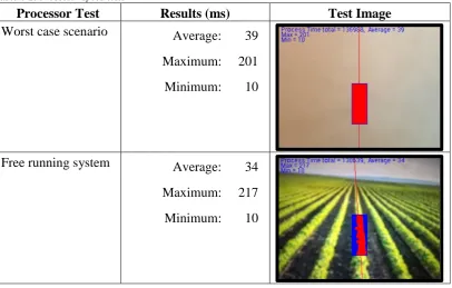
Table 6-2: Processor speed tests ... 37
MACHINE VISION AND SENSING WITH AN ANDROID
x
Nomenclature and acronyms
The following abbreviations have been used throughout the text and bibliography:- GPS Global Positioning System
NCEA National Centre for Engineering in Agriculture USQ University of Southern Queensland
SDK Software Development Kit RTK Real Time Kinematic RMS Root Mean Square
XML Extensible Mark-up Language APK Android Package
API Application Programming Interface RAM Random Access Memory
OS Operating System
App Application
MACHINE VISION AND SENSING WITH AN ANDROID
1
Chapter 1:
Introduction
With the continually decreasing numbers of skilled farmers and the ever increasing necessity for agricultural production there is always a great need to increase productivity and efficiency on farms. Vehicle automation has been one of the key ways to do this in the recent past. This project investigates the concept of developing an automated vehicle guidance system using the Android mobile platform.
The Android platform has specifications for an array of sensors that can be used in vehicle guidance applications. This project researches the capability of these sensors being used in vehicle guidance applications with a particular focus made on machine vision techniques that use the camera as the main sensor for vehicle automation.
1.1
Outline of the study
This project aims to lower the cost and complexity of installing an automation system on a farming vehicle by creating a machine vision application on an easily installable and inexpensive mobile device. This is achieved by extending the work conducted by Billingsley (Billingsley & Schoenfisch 1997) and the National Centre for Engineering in Agriculture (NCEA) regarding tractor automation. A demonstrator program using the NCEA algorithm to deduce rows from an image was written and tested on an Android device and produced excellent results in the controlled laboratory environment. This research opens up the future possibility for field trials of an automated vehicle using an Android device. Further to this, other sensor data, such as GPS, accelerator, and geomagnetic, could be added to the program to try to improve the vehicle accuracy and response time.
1.2
Global food production
The United Nations Food and Agriculture Organisation expects worldwide food production will need to increase 70% by 2050 to sustain the predicted 9.1 billion people on the planet(FAO 2009). These figures indicate that there is a great need for increased agricultural production in the future. Despite the need for this increase in food production Australia recorded a drop of 5% of Australian farming businesses from 2011-12 with only 115,000 farming businesses recorded in 2012 (Australian Bureau of Statistics 2013). With decreasing farming businesses and the need for increased food production automation of farming vehicles is a logical solution.
1.3
Farm vehicle automation
MACHINE VISION AND SENSING WITH AN ANDROID
2
resulting in greater crop yields while also enhancing operational safety (Ming et al. 2009). Global Positioning Systems (GPS) and machine vision are currently the two standard approaches for the automated control of agricultural vehicles used to follow rows of crops however other sensor based guidance methods are around (Emmi et al. 2014). .
1.4
Machine vision
Machine vision has been used for the automation of farming vehicles for a number of years now, however setting up vehicles for this type of automation requires specific technical skills and multiple pieces of expensive bulky equipment. This project extends the machine vision row following technique described by Billingsley (Billingsley & Schoenfisch 1997) by developing an Android application that shows the capability of replicating this machine vision technique on a small portable mobile device.
1.5
Android mobile operating system
Recent development in mobile technology has meant that inexpensive mobile devices have come on the market with inbuilt sensors similar to those used for automated vehicle guidance. This makes them a reasonable solution for implementing a tractor guidance system. Use of a mobile device would eliminate the installation of external cameras or internal processing units in tractor thereby reducing the cost and complexity of putting in automated guidance systems. Despite extensive research and development into tractor guidance systems, no research and development into implementing a tractor guidance system on a mobile device was found in the literary search for this dissertation.
1.6
Research objectives
This project aims to lower the cost and complexity of installing an automated guidance system on a farming vehicle by testing the capabilities of an Android device performing such a task using machine vision. The official project specifications can be found in 1.1.1.1.Appendix A along with changes that were made to the original specification. The updated project specification found in Appendix 1.1.1.1.A.2 identifies the research objectives as:
Review automated agricultural vehicle guidance systems
A review of agricultural vehicle guidance systems was conducted to identify the differing techniques and algorithms used in automated row following guidance.
MACHINE VISION AND SENSING WITH AN ANDROID
3
A review of android sensors, devices, and software was conducted to identify available hardware and related software for items such as a camera that can be used for vehicle automation.
Write and test an Android demonstrator application
This objective involved accessing the video stream in Android memory, manipulating the pixel data, annotating the image, apply the NCEA line fitting algorithm, and outputting information to show steering correction data.
1.7
Conclusions
This project resulted in the development of a demonstrator application written on an Android device that is capable of identifying crop rows through the use of machine vision. This application has kept RAM usage to an average of about 17 MB while processing the 30 fps 320x240 resolution image in an average of 34 ms per frame during typical circumstances.
MACHINE VISION AND SENSING WITH AN ANDROID
4
Chapter 2:
Farm vehicle automation
This chapter covers the history of automation for farming vehicles. An analyses of current navigation, computational, and control methods used in agricultural automated guidance systems is also conducted.
2.1
History
For over 60 years there has been research into the automated guidance of agricultural vehicles with automation to relieve the operator of continual steering adjustments the most frequently cited reason (Wilson 2000). Over these 60 years the operator of the vehicle has kept the same job of vehicle guidance and equipment operation however the vehicles have increase dramatically in size and power and this increase in vehicle power has led to an increase in vehicle speed and equipment size. This increase in speed and size has made the operators job of staying on course all the more valuable and difficult as any deviation will result in a greater area missed or double worked. Having a vehicle that stays on course is not only economically viable but the decrease use of chemicals, fuel consumption, and improper soil tillage make it environmentally viable too. With these things in mind the need to automate vehicle guidance is ever more desirable. Autonomous guidance of a vehicle not only enhances operator safety, but it also increases accuracy and productivity resulting in better economic return and better environmental impacts (Han et al. 2004).
Automated vehicle guidance has been implemented in many fashions over the last 60 years. Morgan (Morgan 1958) and later Brooke (Brooke 1972) wrote about a tractor automated by buried leader cables. Palmer and Matherson (Palmer & Matheson 1988) and also Searcy (Searcy et al. 1990) wrote about the use of radio beacons positioned in a field as a method of automatically navigating a vehicle. These two early autonomous methods were not implemented in many agriculture situations due to the initial expense of the equipment and the limited capability of the radio beacons. It wasn’t until the 1980’s with the exploration of machine vision that farm vehicle automation began to become reasonably priced with respectable accuracy as described by both Reid (Reid, Searcy & Babowicz 1985)and Gerrish (Gerrish et al. 1985). Reports by Larsen (Larsen, Nielsen & Tyler 1994) and Bell (Bell 2000) then note the use of GPS based guidance systems emerging in the 1990’s.
MACHINE VISION AND SENSING WITH AN ANDROID
5
1. Sensing – This is the collection of information from the surrounding environment.
2. Decision making – The sensors lead to a piece of hardware that uses a software algorithm to determine the best course of action for the vehicle to take.
3. Acting – After decision making the hardware/software device sends a message to the vehicle to carry out the task it deemed most appropriate.
2.2
Machine vision
Machine vision is one of the main techniques used for the automated guidance of agriculture vehicles. Machine vision is a relative control mechanism as it relies on a camera image to tell the vehicle its current position relative to the image captured by the camera. While there are varying techniques used in vehicle guidance machine vision applications, all machine vision for agricultural vehicle automation can be broken down into three main areas.
1. Image acquisition - An image is taken of the vehicle surroundings, it is then digitised and placed in memory. This is generally done through a camera mounted on the farming vehicle.
2. Image processing – The image is then placed through an algorithm that identifies the vehicle’s location and then outputs control signals to the vehicle’s actuator.
3. Output control – The signal controls are received by an actuator that is used to steer the vehicle in the desired direction.
MACHINE VISION AND SENSING WITH AN ANDROID
6
Shen (Shen & Liu 2007) used a similar technique where an RGB image from the camera doubles the green to make a R2GB image. Each pixel is then checked against a threshold. This image is then segmented into greyscale where it is again compared against a threshold. If the threshold is met the pixel is then changed to white otherwise it is changed to black. The image is then processed using dilation processing, an acnode filtering technique, a midpoint encoder operation, and is finally improved with a Hough transform. This machine vision technique allowed row following at 3.5 m/s. Jiang (Jiang, Wang & Liu 2015) recently reported on a technique that uses a five stage analysis technique consisting of methods similar to Shen. The camera image is transferred into grey scale and it is then checked against a threshold and transferred again into a black and white image. An estimation of the row centre points is calculated and multiple regions of interest are found. A clustering method is then used to confirm the centre points of the rows. This is finally followed by a linear regression technique to determine the centre for the crop rows. This technique reports accuracy and processing time greater than a standard Hough transform method.
A study carried out by Zhang (Zhang, Cheng & Zhang 2008) also used a R2GB image converted to grey scale and finally to back and white using a threshold. A horizontal scan of the image pixels then identifies the target regions and points. These target points are then clustered according to the abscissa of two adjacent scanned lines. Three clusters are passed through a known point Hough transform to identify a regression line and the crop rows.
2.3
GPS
GPS.Gov ('GPS.Gov' 2015) describes GPS as a United States Department of Defence owned collection of 24 geo-synchronous space satellites that broadcast location and time information to any position on earth where there is line of sight between the satellite and the receiver. GPS.Gov describes GPS as being essential for the development and implementation of precision agriculture. While GPS was the first satellite system to broadcast location and time information other countries around the world now have their own satellite systems in place such as the Russian GLONASS and the European GALILEO satellites.
The GPS Standard Positioning Service Performance Standard (Defense" 2008) Specifies that the worst case for accuracy of the GPS service is a pseudorange accuracy of 7.8 meters at a 95% confidence level, which equates to a worse case of about 3.5 meters horizontal accuracy. The horizontal accuracy is effected by environmental conditions between the GPS receiver and the GPS satellites. Clearer environmental conditions and access to a greater number of satellites will improve the horizontal accuracy of the GPS receiver.
MACHINE VISION AND SENSING WITH AN ANDROID
7
vehicle to follow. These co-ordinates are generally saved when the crops are planted. Alternatively, the co-ordinates can be programmed into the GPS so that the automated vehicle will know which path to follow. Both Abidine (Abidine et al. 2002) and Gan-Mor (Gan-Gan-Mor & Clark 2001) mention the versatility and accuracy of GPS when used for agriculture tasks such as sowing, tilling, planting, cultivating, weed control, and harvesting. Because of its accuracy, ease of use, and its ability to not be affected by any inconsistency in visual camera data it has become the most popular technique in automated guidance of agricultural vehicles.
While an accuracy of 3.5 meters isn’t precise enough for use in vehicle automation, various signal correction techniques can be implemented to correct the inaccuracies of GPS making it accurate enough for vehicle automation. Keskin (Keskın, Say & Görücü Keskin 2009) evaluated low cost GPS receivers for precision in agriculture and found an RMS error of 1.48m on straight crop row tests. Gan-Mor (Gan-Mor, Clark & Upchurch 2007) notes that differential correction systems are often put in place to reach accuracies below 1 meter. Gan-Mor reports that a differential correction system called Real Time Kinematic (RTK) GPS is used to gain an accuracy down to about 1cm which has made this technique very popular for automatic guidance systems in row-crop operations. There are a great number of examples of the accuracy obtained with RTK GPS two of which are Sun (Sun et al. 2010) who recorded a 2cm RMS error on row crops and Perez-Ruiz (Pérez-Ruiz et al. 2012) who reported an RMS error of only 0.8cm when using RTK GPS on crop rows. Kise (Kise et al. 2002) even obtained RMS errors of only 6cm when using RTK GPS on a sinusoidal path. As with any differential correction system RTK requires the use of a base station and complicated algorithms to reduce or remove any errors between the base station and the GPS receiver. This added complexity dramatically increases the price of the equipment and is one of the downsides to RTK GPS (Gan-Mor, Clark & Upchurch 2007). Another disadvantage of GPS is that the signal will not work in shielded areas and will loose accuracy if the right environmental conditions aren’t met.
2.4
Other sensing techniques
There are various other sensing techniques that have been mentioned in several studies however none of these techniques currently have the popularity that GPS and machine vision currently hold. Odometry was used in experiments by Borenstein (Borenstein 1998) and later by Perez-Ruiz (Pérez-Ruíz et al. 2014) however odometry tends to accumulate errors rather quickly eventually leading to large lateral errors in the vehicles location.
MACHINE VISION AND SENSING WITH AN ANDROID
8
environmental conditions however it has shown some faults due to laser measurement distortion when the vehicle is traveling on uneven ground.
MACHINE VISION AND SENSING WITH AN ANDROID
9
Chapter 3:
Android Software Development Kit
To date sensors and decision making hardware used for automated guidance have involved bulky equipment that must be fixed to agricultural vehicles, however modern mobile devices have GPS and camera systems built in as well as other sensors that can be used for automated guidance. Of the many mobile devices available the Android operating system has a significant share of the market and supports software and hardware for GPS, video camera, accelerometer, gyroscope, light sensor, Bluetooth and other sensors useful to build an automated guidance system (Moore et al. 2014) This section of the dissertation covers the specifics about the Android Software Development Kit (SDK) that was used for development of this project. This section omits the hardware specifications for Android devices as each device has differing hardware options dependant on manufacturer and model. The underlying software for control of this hardware however is covered as all android device software is run using the Android SDK. All specifications in this section of the dissertation are taken from Android’s official website ('Android Developers' 2015).
While this chapter gives a general overview of the Android SDK, Chapter 5: has the specific details of how Android software was used during the creation of this project
3.1
Background
The Android platform involves Android applications that are installed and run on devices that use the Android operating system. The Android operating system (OS) is the world’s most popular mobile operating system and is deployed on hundreds of millions of devices in over 190 different countries around the world. The OS is built using open-source Linux and controls all of the software and hardware within the mobile device. Android version 5.1 is the most recent operating system which introduced support for 64-bit architectures.
Android applications are written in the Java programming language and makes use of Extensible Markup Language (XML) resource files. The Java files tell the Android OS what the program is to do while the XML files tell the operating system what resources are needed to run the application. When compiled the Android SDK will package all of the Java code and XML resource files into an Android package (APK). This APK file is then installed on Android devices within its own virtual machine and it is within this virtual machine that the application is run. This allows the OS to control what hardware and software each application has rights to access.
MACHINE VISION AND SENSING WITH AN ANDROID
10
virtual machine performs routine garbage collection to free memory that is no longer in use.
3.2
Camera
The camera is the main sensor used for this project. It is a hardware based sensor that has different specifications for every Android device and is controlled using the android.hardware.camera class for all Android software prior to Android 5.0, and the android.hardware.camera2 class for all devices running Android 5.0 or higher. Android 5.0 was released in November 2014. The android.view.SurfaceView class is another useful camera class that is used within this project to present a live camera previews frames both to other sections of code and to the device screen. Additional details of how the camera was used during this project can be found in section 5.4
3.3
GPS
Android GPS accesses satellite data to specify the device’s current longitude and latitude in degrees, minutes, and seconds. The software used to access this sensor is held in the android.locations class. GPS differential correction techniques cannot currently be used on Android devices without additional expensive hardware which restricts the accuracy of Android GPS to 3m. This inaccuracy without additional hardware made Android GPS not acceptable use in this project.
3.4
Other sensors
3.4.1 Accelerometer
An accelerometer is a hardware based sensor that has different specifications for every Android device and is used to measures the acceleration force, in 𝑚/𝑠2 , that is applied to all three physical axis (x,y,z). Almost every Android device has an accelerometer and they use about 10 times less power than other motion sensors. Common uses for an accelerometer are to detect the motion of an object in a given direction. The x, y, and z motion values will be 0 𝑚/𝑠2 when the device is stationary, will increase when moved toward the arrow, and will decrease when moved away from the arrow. All axis are also subject to the force of gravity (9.81𝑚/𝑠). A high pass filter can be applied to the accelerometer to remove the force of gravity and give linear acceleration only, alternatively a low pass filter can be applied to the accelerometer which isolates the force of gravity.
MACHINE VISION AND SENSING WITH AN ANDROID
11
have the potential to be used in the future development of the Android vehicle guidance method that has been used in this dissertation.
3.4.2 Geomagnetic
The Android geomagnetic sensor is a hardware based sensor. The geomagnetic sensor software data is held in the android.hardware class and is used to measures geomagnetic force in 𝜇𝑇 on the x, y, and z axis. As with the accelerometer information, geomagnetic information has not been used in this dissertation yet details of the Android geomagnetic sensor have been included as it does have the potential to be used in the future development of this Android vehicle guidance method.
3.5
Data handling
Applications run on an Android device have access to system RAM, data storage, and data processing capabilities. Each specific device will differ in hardware specifications but each will use the same Android SDK classes.
Android uses an automated garbage collector to free up RAM resources that are no longer needed and also uses both paging and memory mapping to manage memory. Any created object will remain within RAM until the app releases the object for collection by the garbage collector, which will run more often when there are more resources in RAM. Android recommends that background services are used sparingly and terminated when no longer in use to help free system RAM.
Android devices are increasingly being released with multiple processors and the Android SDK version 3.0 and above makes it possible to run threads in parallel. This is achieved through the use of the Java Runnable and Thread classes in conjunction with the ThreadPoolExecutor class. Running different threads on different processors will allow for parallel processing of data as is the case with the application built during this project.
While the developed application does not store any data permanently, the main Android data storage options are still shown here for reference.
Key-value sets – This is used to save a small collection of key-values. It uses the SharedPreferences API where creation of a SharedPreferences object creates a file containing key-value pairs and provides a method to read and write them. The created file can be either private or shared and is managed by the framework.
MACHINE VISION AND SENSING WITH AN ANDROID
12
SQL Database – This is used to store structured data that can be read in any order. The android.database.sqlite is the Android package that is used. This technique requires a database schema and can be stored on internal or external memory. Access restrictions can also be applied.
3.6
Bluetooth and Wi-Fi
MACHINE VISION AND SENSING WITH AN ANDROID
13
Chapter 4:
NCEA vision guidance system
The machine vision technique used for row following that Billingsley (Billingsley & Schoenfisch 1997) noted in the NCEA study in 1997 has been adopted as the machine vision algorithm for this project. This algorithm was selected for its simplicity and ease of portability to an Android platform. This chapter covers the specifics of this NCEA machine vision guidance system.
4.1
History
The NCEA began research into machine vision use in agriculture in the early nineties. Since that time the NCEA has developed a machine vision animal identification system, a macadamia nut counting system, and a vehicle automated guidance system. The development of a machine vision guidance system lasted three years and resulted in a machine vision prototype that was relatively insensitive to weeds and could withstand the fading in and out of crop rows while still keeping the vehicle on the correct bearing. This three year study involved cameras being externally mounted onto the tractor, as well as internal processing units being integrated into the tractors. Six prototypes of this machine vision technique were tested in the field and results showed that an accuracy of 2 cm was able to be maintained at 35 km/h.
This system originally used a black and white camera taped to the roof of a David Brown tractor. The captured image was 768x96 pixels and was transferred over cabling to a PC installed inside the tractor by direct memory access where a program written in C processed the image data. This program then output steering commands over a cable to a stepper motor connected via belt drive to the steering wheel of the tractor. If there was some type of system error an audible warning sound was outputted through the PC speakers and the system would revert to manual control. Although there have been several refinements to this system as technology and resources became available, the basic flow of information and the connection of hardware elements has not changed much between versions.
During field tests the overall response from users was positive with all users impressed with the speed, accuracy and efficiency of the system. Complaints that were received from the users were regarding the complexity of setting up and calibrating the system. These complexity issues may be fixed with further development of the Android application developed in this paper.
4.2
Image acquisition
MACHINE VISION AND SENSING WITH AN ANDROID
14
to be held in separate data bits which makes it less sensitive to changes in lighting conditions.
The image is then moved into memory using direct memory access where each pixel is compared to a threshold level that is set at the start of the program. The original system would degrade system performance by switching the video output between the processor and a connected monitor. Later models allowed dual image streams so that the video feed could be viewed and annotated with real time data without reducing overall system performance.
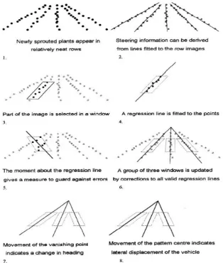
The tractor operator assigns adjustable viewports to the incoming image which identify the pixel locations of one row of crops. Then each pixel within each of these viewports is compared against the threshold level set at the start of operation. Pixels that are greater than this threshold level are marked as plant and are used for further processing.
The tractor operator also sets the proportion parameter at the start of the program which indicates the expected proportion of pixels identified as plant within each window. This proportion value depends on the growth stage of the plant with typical values being 0.1 for a new plant to 0.5 to a mature plant. The total number of plant pixels for each window in each frame are then compared and this data is used to increment or decrement the next frames threshold level. This makes the system very insensitive to fluctuations in lighting conditions.
4.3
Image processing (Identification of rows)
The acquired image data is processed using a technique similar to linear regression to identify the centre of each crop row. As each positioned viewport contains only one crop row, drawing a line which minimises the viewport moment of inertia when spun around this line identifies the line of best fit and the centre of a crop row. Billingsley (Billingsley & Schoenfisch 1997) showed the cost function to calculate the moment of inertia for each viewport as:
C = ∑ ∑ m(x, y) ∗ (x − offset − slope ∗ y)2
x.yewindow ( 4.1)
where: 𝑥 is the x coordinate 𝑦 is the y coordinate
𝑤𝑖𝑛𝑑𝑜𝑤 is perimeter of the viewport window
𝑚(𝑥, 𝑦) is a matrix of x and y coordinates identified as plant 𝑜𝑓𝑓𝑠𝑒𝑡 is the x coordinate for the line of best fit
𝑠𝑙𝑜𝑝𝑒 is the slope of the line of best fit
MACHINE VISION AND SENSING WITH AN ANDROID
15
of best fit. The line of best fit slope and offset parameters were calculated within the C program by providing solutions to the following simultaneous equations:
∂C
∂offset= 0 and ∂C
∂slope= 0 ( 4.2)
Which Billingsley identified can be solved using the following formulas for identifying the lateral offset corrections and the slope corrections respectively:
𝑓𝑖𝑡𝑂𝑓𝑓𝑠𝑒𝑡 =𝑚𝑥∗𝑚𝑦𝑦−𝑚𝑥𝑦∗𝑚𝑦
𝑚∗𝑚𝑦𝑦−𝑚𝑦2 ( 4.3)
𝑓𝑖𝑡𝑆𝑙𝑜𝑝𝑒 =𝑚∗𝑚𝑥𝑦−𝑚𝑥∗𝑚𝑦
𝑚∗𝑚𝑦𝑦−𝑚𝑦2 ( 4.4)
where: 𝑚 is the total number of pixels identified as plant
𝑚𝑥 is the total x axis moment about the viewport horizontal line 𝑚𝑦 is the total y axis moment about the viewport vertical line
𝑚𝑥𝑥 is the second moment of area 𝑚𝑦𝑦 is the second moment of area 𝑚𝑥𝑦 is the total second moment
After the offset and slope values for the line of best fit are identified, the correction values needed to obtain these offset and slope values are calculated. These correction values are then converted into steering commands outputted to the actuator that steers the tractor.
A ratio to check the quality of the results is run by comparing the moment of inertia about the line of best fit against the moment of inertia about the horizontal axis. This ratio gives a “quality” value and the correction data is only acted upon if the quality is greater than 4. This increases the accuracy of the program by only acting upon good quality data containing adequate plant values and not acting upon data with scattered plant values due to weed growth, pests eating the crop.
While only one viewport is needed for vehicle automation the use of a a greater number of viewports is recommended so that vehicle automation can continue in the event of a viewport not being able to output correction data to the actuator. If all viewports contain poor quality data 3 times in a row, then an alarm sounds and the vehicle control reverts back to manual.
MACHINE VISION AND SENSING WITH AN ANDROID
[image:27.595.117.432.85.456.2]16
Figure 4-1: NCEA linear regression image analysis algorithm (Billingsley & Schoenfisch 1997)
4.4
Actuator control
The correction values produced after the algorithm has been run are converted into steering commands outputted to the actuator that steers the tractor. The lateral movement steering commands are calculated using either the fitOffset correction value, or by identifying the “vanishing point” of where the best fit lines from multiple viewport meet at a point. The fitSlope correction value is used to identify the angular displacement of the vehicle and issues steering commands accordingly. These are just the basics for the actuator control and further detail has been omitted as it is beyond the scope of this project.
4.5
System testing and evaluation
MACHINE VISION AND SENSING WITH AN ANDROID
17
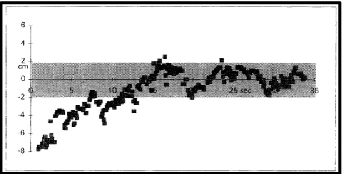
the movement of the paper from left to right was determined. The actual location of the paper and the detected position of the paper were recorded independent of each other and locations of the paper were then compared. Figure 4-2 below shows that the algorithm achieves good quality results. This figure shows the actual position of the paper as the top line of dots and the detected position of the paper as the bottom line of dots.
Figure 4-2: Actual vs captured data testing the performance of the machine vision algorithm (Billingsley & Schoenfisch 1997)
[image:28.595.113.454.185.373.2]A full system test was then carried out where white lines were marked on the ground and the capabilities of the whole system were evaluated. During this test a secondary camera was attached to the axil and recorded the system performance. The data for this test was taken back to a laboratory and results were recorded. These results are shown below in Figure 4-3 and they show that the system has achieved an accuracy of 2cm.
[image:28.595.114.456.509.682.2]MACHINE VISION AND SENSING WITH AN ANDROID
18
Chapter 5:
Methodology
This chapter identifies the method used to develop an Android based autonomous farm vehicle. This involved writing several short programs in Android code to identify some key aspects of the Android SDK followed by writing more specific code used in this projects’ Machine Vision demonstration application. The machine vision algorithm discussed in Chapter 4: was then applied on an Android device before code optimisation was carried out
5.1
Development tools and techniques
This section covers the programming methodology used during this project and lists the Integrated Development Environments (IDEs) used for development and testing of this code.
5.1.1 Agile programming technique
The agile programming techniques described by Martin (Martin 2003) was used for the development of software during this project. The agile programming technique generates small portions of computer code before testing its accuracy and usefulness. This allows for a lot of usable code to be written and tested in a short time as not a lot of preparation goes into the planning process for the long term goals of the program. As Dingsoyr identifies (Dingsoyr 2010) that with agile programming there is a vague idea of what the end goal will be however more focus is made on individual components that need to be developed now in order to get useable software as quickly as possible. This leads to a very fast cycle of planning, requirements analysis, design, coding, unit testing, and acceptance testing.
An agile programming methodology was selected over the more traditional waterfall method for the following reasons the following reasons as stated by Martin (Martin 2003):
Risk management – This project involved a lot of risk as a lot of aspects of its development were unknown at the start of the project and as states, Agile programming has the ability to minimise this risk because of its ability to adapt to change so quickly. Small unit testing of code quickly defines the usefulness of this code thereby eliminating the possibility of writing a lot of code only to find in a few weeks’ time that it isn’t useful for this application.
MACHINE VISION AND SENSING WITH AN ANDROID
19
Quality – Code is tested as individual components are created so the quality of each individual segment is guaranteed prior to full system integration.
Design – A test driven approach is used to define the final requirements of the system allowing the system to be designed and refined as system modules are built.
Segmentation – Agile programming segments code so only one aspect is studied at a time making it suitable for this project.
While agile programming has many benefits suitable for this project many published authors such as Rierson (Rierson 2013) do not recommend agile programming for safety-critical software projects such as those used in the automotive industry. The Institute of Electrical and Electronic Engineers’ ('IEEE Standard Glossary of Software Engineering Terminology' 1990) definition of a safety-critical software is any software where the failure can lead to a hazardous state, so by definition the automation of any vehicle falls under this category. The International Organization for Standardization’s (ISO) international standard ISO26262 for road vehicle functional safety defines a coding requirement for road vehicle functional safety that is more structure based like that of the waterfall model.
Although this project will eventually lead to a safety-critical software project, at this stage of development there are no safety-critical aspects involved. All testing for this project has been run as simulations in a controlled laboratory therefore allowing the use of the agile programming method. Future development of this application would have to review the programming methodology used and then take that into consideration when designing the enhanced system.
While the benefits of using Agile programming for this project far outweigh limitations a few things that were considered during the development of this project were:
System Testing - During agile programming components are assumed to interact nicely if they work as individuals but this is not always the case. Agile programming doesn’t test with a system as a whole until the final stages of development.
Abstract code – Agile programming can lead to a lot of abstract code which Android Developers ('Android Developers' 2015) list is not a desireable thing when coding for a mobile because of the memory usage.
5.1.2 Integrated Development Environment (IDE)
MACHINE VISION AND SENSING WITH AN ANDROID
20
be investigated some compatibility issues became prevalent between the computer vision libraries, Android Studio, and the Java Development Kit (JDK) version 1.7 that was being used. After these issues could not be resolved the Intellij IDE was used for the remainder of the coding and testing.
5.2
Elementary code
This section covers elementary code developed to become familiar with the Android SDK and the recommended best coding practices to follow during development. Some available computer vision libraries are also investigated in this section.
5.2.1 Android developers
Initial coding design and development for all basic Android modules followed the online training modules defined by Android developers ('Android Developers' 2015). Android developers best coding practices. Android Developers also has a section for the best coding practices to follow during program development. As this project was completed using the agile programming method which primarily focuses on writing working code before optimising code, the first stages of this project didn’t follow all of these coding practices however after the correct working code was found it was then cleaned up and altered to incorporate some of these Android coding practices regarding memory management, and Multithreading. One limitation of this application is that some of the coding practices used are not optimal such as leaving application fatal operations outside of a try, catch block. This was due to deadlines for project completion. Details about the Android development environment learnt from doing this developer training can be found in 1.1.1.1.Appendix B.
5.2.2 Computer Vision libraries
Two open source computer vision libraries were investigated to see computer vision techniques that are available. The two libraries investigated were OpenCV and BoofCV.
OpenCV – a C++ based computer vision library
OpenCV.org (OpenCV 2015) states that this bundle of computer vision classes and libraries is available under a BSD license making it free for both academic and commercial use. Development began in 1999 and while OpenCV is primarily a C++ programming language it also has Java interfaces and it supports the Android operating system.
BoofCV - a Java based computer vision library
MACHINE VISION AND SENSING WITH AN ANDROID
21
both academic and commercial use. Development of BoofCV began in 2011 and it is written in Java making the wide range of prewritten libraries and example code compatible with the Android operating system.
Example code segments using both OpenCV and BoofCV were reviewed with both libraries being suitable for this project. While OpenCV (OpenCV 2015) claims that their open source library is the fastest because it is written in the native C language Abeles (Abeles 2012) claims that BoofCV is faster when processing higher level algorithms. Neither of this data could be tested and confirmed.
In the end BoofCV was selected over OpenCV as the primary computer vision library for use in this project primarily because the classes are written in Java which is compatible with Android systems with only a slight bit of modification. Due to time constraints and a slight pre-existing developer knowledge in Java BoofCV was the best option available.
5.3
Android machine vision program development
The following section covers the entire development process used to create an Android based application that is successful in identifying crop rows. The Android package files generated during this process can all be found in 1.1.1.1.Appendix C.
5.3.1 Program description
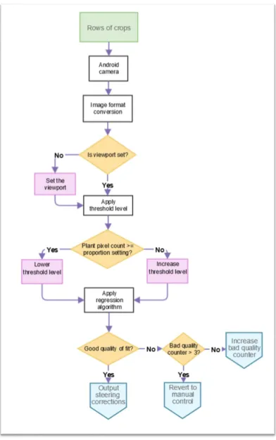
The main aim of this application is to test if a machine vision program capable of identifying crop rows can be successfully developed and run on an android mobile device. The algorithm detailed in Chapter 4: that identifies straight crop rows was selected for application development and all testing of this application was conducted in a controlled environment under controlled conditions.
MACHINE VISION AND SENSING WITH AN ANDROID
22
[image:33.595.120.513.126.752.2]of information for this process is found in Figure 5-1. This flow of information repeats for every frame that the camera produces.
MACHINE VISION AND SENSING WITH AN ANDROID
23
5.3.2 Application limitations
This application has the following limitations
The algorithm is designed to identify straight crop rows and as such doesn’t have the ability to identify crop rows that are curved.
This is an elementary test version of an Android based machine vision application and not a production version. One result of this elementary code is that there is no user interface for this application and any changes in system constants has to be hard codded and recompiled in order to work.
Testing in a controlled laboratory ensured perfect conditions for the machine vision application to function. Testing with noisy data was beyond the scope of this project therefore the applications ability to work in an uncontrolled environment is unknown.
During testing an error of half a pixel length was identified and the source of the error could not be located before this document was published. Details of this error can be found in section 6.5 .
This application does show the vanishing point information with what is assumed to be the correct calculations for identifying this point, however testing for the accuracy of this value had not been performed in time for this document to be written.
This application does not follow all of the recommended Android development coding practices and as such some of the code developed is not optimised for performance or usability. Such things as leaving application fatal operations outside of a try, catch block have not been followed which can lead to the application terminating when certain system parameters aren’t met. Due to deadlines for project completion the code could not include all recommended practices.
5.3.3 Initial development setup
[image:34.595.113.529.641.767.2]After the initial investigation into Android coding and available computer vision libraries the development parameters in Table 5-1 were put into place.
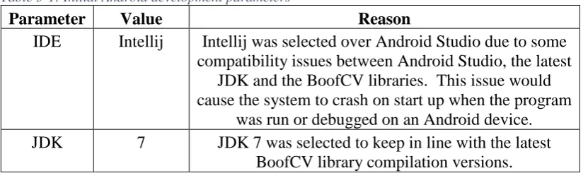
Table 5-1: Initial Android development parameters
Parameter Value Reason
IDE Intellij Intellij was selected over Android Studio due to some compatibility issues between Android Studio, the latest
JDK and the BoofCV libraries. This issue would cause the system to crash on start up when the program
was run or debugged on an Android device. JDK 7 JDK 7 was selected to keep in line with the latest
MACHINE VISION AND SENSING WITH AN ANDROID
24 Computer
Vision Library
BoofCV BoofCV was selected because the libraries are written in Java which makes them compatible with the Android Operating System.
Android SDK
Min – 10 Target – 17
Android version 10 (2011) is the minimum version that BoofCV has been fully tested and Android version 17 (2013) was the version loaded on the equipment used for testing.
The AndroidManifest.xml file specifying the Android SDK and the application start-up values can be found in 1.1.1.1.Appendix C.
The application starts by accessing the Row_Follow_Main.java class as specified by the Android manifest. This class begins by importing all of the Android, Java, and BoofCV libraries needed for operation. This main class extends the Android Activity.java class allowing the application to display data to the screen and to securely deal with interruptions to the application, and it also implements the PreviewCallback.java class which delivers copies of the video frames as they are captured by the camera. The global constants and variables used by the application are then specified.
The onCreate method is the first method that is called which requests access to the main screen from the Android operating system and then creates the CameraPreview and Visualisation objects before adding them to a FrameLayout object that allows these two items to be output to the device screen. The created Visualisation object uses its onDraw() method to scale the Bitmap image stored in the ‘output’ variable to the required size and then attaches it to the canvas for output to the device screen. The ‘output’ variable is a copy of the camera image converted into Bitmap format. This variable is updated frame by frame as new images arrive from the device camera. This variable is accessed by two separate threads so write access to it needs to be synchronised to avoid information mismatch. The CameraPreview.java class and the use of threads is explained in detail in section 5.4 1.1.1.1.Appendix B also contains information regarding threads.
Additional methods such as onPause() and onResume() which handle interruptions to the application are available in the event device applications are switched.
MACHINE VISION AND SENSING WITH AN ANDROID
25
5.4
Video stream access
This application gets a 320x240 image at 30 fps in NV21 format from the device camera which is then converted into RGB format. Calculations for plant identification and for further use in the row following algorithm use a viewPort which is a sub-section of pixels within this RGB camera image. The annotated image is then converted into Bitmap format before being output to the device screen. This section of the paper explains the procedures performed to achieve this. The Java code explained in this section can be found in 1.1.1.1.Appendix C.
5.4.1 Permissions and features
The first step in accessing the video steam is specifying the camera permissions and application features within the Android manifest as is shown in Figure 5-2. This manifest extract shows that the application must gain permission to use the device camera from the Android operating system. It also specifies that the Android device used to run this application must have a rear facing camera which has autofocus capabilities. The rear facing camera is needed for this application as the user must be able to access the device screen while the camera views the upcoming crop rows.
Figure 5-2: Android Manifest camera permissions
5.4.2 CameraPreview.java
This application accesses the camera hardware through the CameraPreview.java class shown in Appendix 1.1.1.1.C.3.
This class extends the ViewGroup.java class, which allows it to create interface layouts. The CameraPreview class also implements the SurfaceHolder.Callback interface, which is used to connect the camera hardware to the application. This class is responsible for passing image data to the main Row_Follow_Main.java class each time the camera captures a new frame. Because the Row_Follow_Main.java class implements Camera.PreviewCallback and has an onPreviewFrame() method, each time the camera gets a new frame the CameraPreview object will send the image data to this method. The onPreviewFrame() method then copies the incoming byte array, representing the new camera frame, to the processByte array used for processing the image.
5.4.3 Resolution, Framerate, and Camera class
MACHINE VISION AND SENSING WITH AN ANDROID
26
This method returns the rear facing camera by default. The camera resolution for the image returned is set to 320x240 at 30fps. This is achieved by accessing the Camera.Parameters.java class and is set using the global variables CAMERA_WIDTH and CAMERA_HEIGHT. 320x240 was selected as the resolution size as this offered a good balance between displaying a clear image and keeping resource usage to a minimum. 30fps was the frame rate selected because it was fast enough for data acquisition while not unnecessarily using the device’s resources. This frame rate also shows a smooth transition between frames for the displayed image output. The Camera.java class was one of the classes that got deprecated at the end of 2014 with the release of Android SDK 21 and the new Camera2.java class. This application continues to use the deprecated Camera.java class over the newer Camera2.java class because of the larger amount of available resources regarding the Camera.java class and the fact that the device used for testing was running an older software version that only supported the Camera.java class.
5.4.4 Image format
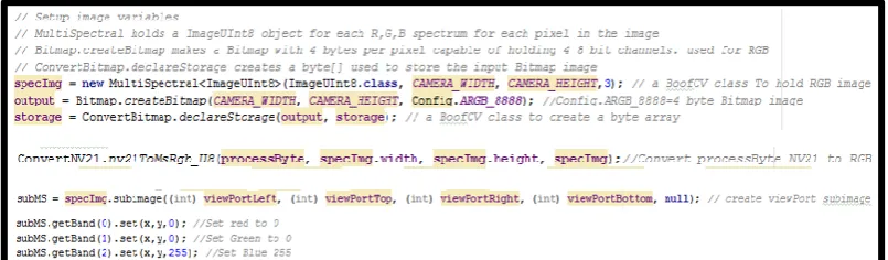
The image is transferred into this application for processing by the device Camera through the CameraPreview.java class as described in section 5.4.2 . This image is in Android’s NV21 YCrCb format. For ease of applying a threshold level to identify plant pixels the image is converted from the NV21 format into 8-bit unsigned RGB format using the nv21ToMsRgb_U8() method of the BoofCV ConvertNV21.java class. This RGB format displays each pixel in the image using three 8bit values representing the colours Red, Green, and Blue, with each having a colour depth range from 0 to 255. Each colour band is stored separately in a BoofCV ImageUInt8 object that is held within a MutliSpectral<ImageUInt8> object. Access to individual pixels is granted through the getBand() method of the MultiSpectral class.
[image:37.595.113.516.634.752.2]After the image has been assessed using the row following algorithm it is converted into a Bitmap using the BoofCV ConvertBitmap.multiToBitmap() method and set to the background of the Canvas object that is used to output the image to the screen. This is done inside a synchronised code block because two separate threads have access to the output object.
Figure 5-3 below shows some code samples used within the application to access and convert between image formats. Further details can be seen in Appendix 1.1.1.1.C.2.
MACHINE VISION AND SENSING WITH AN ANDROID
27
5.4.5 Viewport
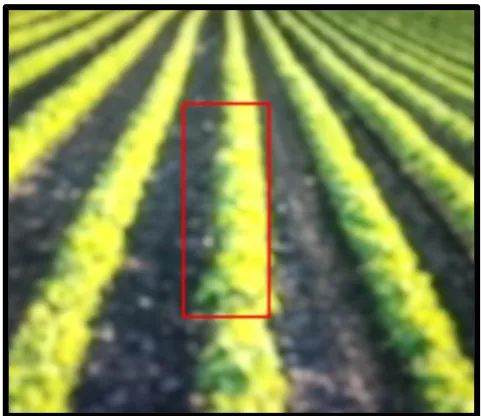
[image:38.595.112.512.319.429.2]A viewport was created using the sub-Image function from the BoofCV Image class. Creation of a sub-Image defines a portion of an image that can be independently used for calculations. This makes the sub-Image ideal for representing a viewport designed to straddle the edges of the crop rows as described in section 4.2 . The boundaries and position of this view port are defined in the setUpApp() method, and The viewport length and width are set by the global variables VIEWPORT_HEIGHT and VIEWPORT_WIDTH. In this application the viewport is 80x30 pixels, and is centred along the x-axis with its centre located at x coordinate 160 pixels which is half the width of the 320 pixel screen. The bottom of the viewport is located at y coordinate 192 which is 1/5 or 48 pixels from the bottom of the screen. Figure 5-4 below shows the program code used to create and access the viewport data and immediately following this code Figure 5-5 shows the resulting viewport displayed on the device screen.
Figure 5-4: Creation and access of the viewport
Figure 5-5: Viewport surrounding one crop row.
5.4.6 Plant Identification
[image:38.595.112.353.461.669.2]MACHINE VISION AND SENSING WITH AN ANDROID
28
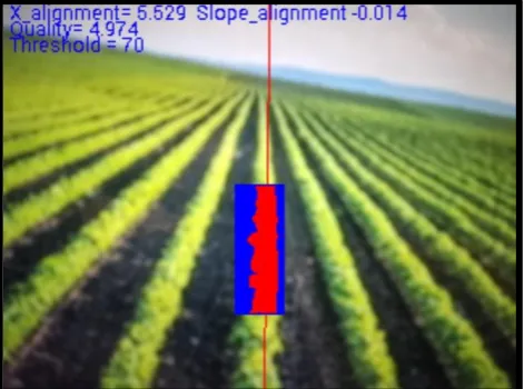
[image:39.595.114.353.230.407.2]equal to the threshold, then the pixel is considered a plant and the pixel x and y coordinate values are then added to an ArrayList for further processing. In this application the original threshold level is set to 128. To help visualize which pixels are plant and which are not within the viewport window, all pixels identified as plant are changed red by setting the Green and Blue values to 0 and the Red value to 255, any pixel that is not a plant is turned blue by setting the Red and Green values to 0 and the Blue value to 255. A coded example of this can be seen in Figure 5-4 above, and in
Figure 5-6 below a crop image with a viewport can be seen where the plant pixels are shown in red and the non-plant pixels in blue.
Figure 5-6: Viewport with plants identified in red
5.4.7 Threads
The application begins on one thread and another is created within the setUpApp() method to handle the time taken to process the video using the row finding algorithm. This is done because the calculations used to identify the crop rows within the image may take longer than the time taken for the cameraPreview to update with a new frame. Without a thread this causes a backlog of frames on this thread until the system runs out of memory and terminates. By creating seperate threads for processing and image acquisition each new frame that comes from the camera through the CameraPreview object is passed to the onPreviewFrame() method which updates the byteArray with the new frame data and sends a thread.interupt() message to let the processingThread class know that there is another frame available for processing. The separate thread then handles the new frame once it has finished with the previous frame. If a third frame arrives before the processorThread accesses the second waiting frame, the second frame is discarded and replaced with the third frame. The processorThread will miss processing frame two but this way no backlog of frames waiting to be processed will occur so the system will not terminate prematurely.
MACHINE VISION AND SENSING WITH AN ANDROID
29
5.5
Image annotation
The Android Canvas.java class was used to annotate the video image after processing had been done. The “output” Bitmap is set as the background of the Canvas which allows annotations to be drawn in the foreground. The image in this application has been annotated with a rectangle outlining the viewport, a line representing the regression line calculated, and some text. This was done using the drawRect(), drawLine(), and the drawText() methods of the Canvas class. The text displays the x_ alignment and slope_alignment correction data to be sent out to the Actuator control, the quality of fit value, and the vanishingPoint information. When the quality variable drops below 4, the regression line is no longer annotated to the screen. This simulates a live system reverting to manual control when the quality of fit is small. Once all annotated data is drawn onto the Bitmap image the mDraw.postInvalidate() method call tells the GUI to update the display to include the newly annotated Bitmap image.
5.6
Row identification algorithm
The following section covers how the NCEA row following algorithm was written using Android code. All of these algorithm calculations are performed on the processThread as described in section 5.4.7 Threads28.
5.6.1 Threshold
MACHINE VISION AND SENSING WITH AN ANDROID
[image:41.595.115.351.86.261.2]30
Figure 5-7:Threshold adjustment for an expected 40% plant density
5.6.2 Regression assessment
After the ArrayList holding all of the plant pixel coordinates is found, a call is made to the assess() method which in turn calls the fit() method used to calculate the regression line, correction data, and the new threshold value. If the fit() method deems the new data is of good quality then the assess() method will overwrite the old correction data held in global variables, with the new frames correction data as well as set up the data needed to draw the regression line.
5.6.3 Regression fit
MACHINE VISION AND SENSING WITH AN ANDROID
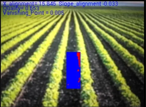
[image:42.595.115.350.86.258.2]31
Figure 5-8: A poor quality fit showing no regression line
5.6.4 Limits
The application has a limit() method that is used to apply limitation on the slope and vanishing point. These limits identify the boundaries of the regression line to ensure that the regression line and correction data is projected in the correct direction. This limit is set using a percentage value representing a percentage of pixel values for the boundary. This application has the limit set at 0.2.
5.7
Actuator control commands
MACHINE VISION AND SENSING WITH AN ANDROID
32
Chapter 6:
Evaluation and optimisation
This section covers the testing methodology and optimisation techniques used for this research. As the agile programming method was used, each section of code produced in the research was written in small segments of code which were individually tested and optimised or discarded until the required result was found.
6.1
Test Equipment
The aim of this research was to see if an Android device was capable of implementing a computer vision algorithm such as the NCEA’s row following algorithm so the written code was only tested using one specific test device. Further testing would need to be done using multiple devices to identify how well the application performed on differing hardware however that was beyond the scope of this research.
A Samsung Galaxy S4 was used for all module testing of this application. Samsung ('Samsung' 2015) listed the specifications for this android device as:
Android OS 4.2.2
Quad Core 1.9GHz processor Full HD Super AMOLED display
2GB RAM
16GB internal memory with up to 64GB external memory CMOS 13MP rear camera and CMOS 2MP front camera
Sensors include Accelerometer, Geomagnetic, Gyroscope, Broadcom BCM47521 GLONASS GPS, AGPS, Bluetooth 4.0
Android code was uploaded to the device using the Android Studio and Intellij IDEs as explained in section 5.1 . The application utilised the test device’s rear facing13MP camera to acquire the image before it was processed. The relevant test results were then displayed on the device’s screen
6.2
Procedure
MACHINE VISION AND SENSING WITH AN ANDROID
33
After some basic code was identified as being of possible use, further testing and investigation went into identifying uses for the code. Android developers list various automated testing tools to aid software development, however this project uses a manual testing method where unit tests for each piece of new code are manually performed and result are checked against predictable calculated values. Code was then edited and optimised or discarded were applicable.
6.3
Video stream access
After many hours researching how to access and process individual pixels from images captured by the Android device’s camera, BoofCV was selected to access the video stream. This was due to its ease of use. BoofCV offered image conversion to a number of formats such as binary, greyscale, RGB, HSV, and BoofCV also offered a range of coded examples to be explored for different computer vision techniques. While OpenCV also contains a wide range of libraries for computer vision, BoofCV was selected as it was written entirely in Java which can be easily ported to an Android system.
For accessing the device camera the application used the Camera.open() method and not the BoofCV recommended cameraPreviewSetup() method. This was done for two reasons. The first being that only devices with rear facing cameras are supported as defined in the Android Manifest so Camera.open will always open the correct rear facing camera, and secondly to limit the memory used to run the application by limiting the amount of code used.
A 320x240 resolution image was had set for use and not BoofCV recommended closest() method to select resolution. This BoofCV method is more flexible as it offers a variety of different resolution option however 320x240 is a fairly standard resolution, and was one which was offered on the test device, so the hard coded option was selected to cut down on code used to write the application. Further application development for use on additional devices may need to include the BoofCV recommended closest() method.
Although different image formats were tested, RGB was selected for this application for its ease of implementation. The starting threshold for RGB was easily defined as G=128, and while other formats such as HSV are often more effective in varying lighting conditions, the use of the varying threshold and the density level within the viewport make this application very effective when dealing with light changes making RGB just as effective.