i
LOW COST MOBILE POWER GENERATOR SYSTEM
CHANG BOON HAI
This report is submitted partial fulfillment of the requirement for the award of Bachelor of Electronic Engineering (Industrial Electronics/ Telecommunication Electronics/
Computer Engineering*) With Honours
Faculty of Electronic and Computer Engineering Universiti Teknikal Malaysia Melaka (UTEM)
ii UNIVERSTI TEKNIKAL MALAYSIA MELAKA
FAKULTI KEJURUTERAAN ELEKTRONIK DAN KEJURUTERAAN KOMPUTER
BORANG PENGESAHAN STATUS LAPORAN
PROJEK SARJANA MUDA II
Tajuk Projek : LOW COST MOBILE POWER GENERATOR SYSTEM Sesi Pengajian: 2010/ 2011
Saya ………...CHANG BOON HAI……… (HURUF BESAR)
mengaku membenarkan Laporan Projek Sarjana Muda ini disimpan di Perpustakaan dengan syarat- syarat kegunaan seperti berikut:
1. Laporan adalah hakmilik Universiti Teknikal Malaysia Melaka.
2. Perpustakaan dibenarkan membuat salinan untuk tujuan pengajian sahaja.
3. Perpustakaan dibenarkan membuat salinan laporan ini sebagai bahan pertukaran antara institusi pengajian tinggi.
4. Sila tandakan ( √ ) :
(Mengandungi maklumat yang berdarjah keselamatan atau SULIT*
TERHAD*
TIDAK TERHAD
________________________________
(TANDATANGAN PENULIS)
Alamat Tetap: LOT 300, JALAN
LOPENG, KAMPUNG LOPENG, 98000,
MIRI, SARAWAK.
Tarikh: 3 MEI 2011
kepentingan Malaysia seperti yang termaktub di dalam AKTA RAHSIA RASMI 1972)
(Mengandungi maklumat terhad yang telah ditentukan oleh organisasi/badan di mana penyelidikan dijalankan)
Disahkan oleh:
___________________________________
(COP DAN TANDATANGAN PENYELIA)
Tarikh: 3 MEI 2011
,
iii
“I hereby declare that this report is the result of my own except for quotes as cited in the references”
Signature : ………
Author : CHANG BOON HAI
iv
“I hereby declare that i have read this report and in my opinion this report is sufficient in terms of the scope and quality for the award of Bachelor of Electronic
Engineering (Industrial Electronics/ Telecommunication Electronics/Computer Engineering*) with Honours”.
Signature : ………..
Supervisor Name : MR. DAVID YAP FOOK WENG
v
vi
ACKNOWLEDGEMENT
First and for most, a sincere gratitude goes to my supervisor Mr. David Yap Fook Weng for his guidance and supervision for completing my final year project through out these two semesters as a final year student. Under his supervision and ideas, the project went on smoother without delay.
Besides my supervisor, I would also like to thank my family, especially my parents and brothers as they have given me spiritual and financial support for any difficulties that I have encountered. For them, love is always at heart even distances away.
vii
ABSTRACT
viii
ABSTRAK
ix
CONTENTS
CHAPTER CONTENT PAGE
PROJECT TITLE i
RECOGNITION ii
ACKNOWLEDGEMENT v
ABSTRACT vi
ABSTAK vii
CONTENTS viii
LIST OF TABLES xi
LIST OF FIGURES xii
LIST OF ABBREVIATIONS xiii
I INTRODUCTION
1.1 Introduction to Project 1
1.2 Objectives 2
1.3 Problem Statement 3
1.4 Scope 3
1.5 Methodology 4
1.5.1 Methodology Flow Chart 5
1.6 PSM Report Overview 6
II LITERATURE REVIEW
2.1 Low Cost Mobile Power Generator System 7
x
2.2.1 Solar Power Projects for Rural Areas 8
2.3 The Theory of the Solar Cell 10
2.3.1 Efficiency 12
2.4 Charge Controllers 12
2.5 DC to AC Inverters 13
2.6 Storage Battery 14
2.7 Solar Batteries 15
2.8 Maximizing Power of Solar Panel through
Solar Tracking 16
2.9 Sun Tracking Method 18
2.10 Light Dependent Resistors 19
2.11 Solar Tracking Sensor Methodology 20
2.12 Motors 22
2.12.1 DC Motor 22
2.12.2 Stepper Motor 22
2.12.3 Servo Motors 23
2.13 PIC 16F877A 25
2.14 LM 7805 26
III METHODOLOGY
3.1 Methodology 28
3.2 Main Components 29
3.2.1 Solar Panel 30
3.2.2 Charge Controller/ Battery Chargers 31
3.2.3 Storage Battery 32
3.2.4 DC to AC Inverter 32
3.3 Design of the Dual Axis Solar Tracker 34
3.3.1 Solar Tracker Free Movement 35
3.3.2 Materials for Dual Axis Solar Tracker
Design 35
xi
3.3.4 Light Dependent Resistors as Solar Tracking Sensors
37
3.3.5 Servo Motors 38
3.3.5.1 Servo Motor Movement 40
3.3.6 LM7805 and LM7806 voltage regulator 42
3.3.7 PIC 16F877A Microcontroller 43
3.3.8 PIC C Compiler Programming Language 45
3.3.9 PIC Kit 2 Programmer 45
3.3.9.1 PIC Microcontroller Program Download Process
47
3.4 Tracking Algorithm 48
3.4.1 Flow Chart of Tracking Algorithm 51
IV RESULT AND DISCUSSIONS
4.1 Result 52
4.2 Solar Power Generator System 52
4.3 Costs for the Low Cost Mobile Power Generator System
53
4.4 Result of Dual Axis Solar Tracker Tracking 54
4.5 Mechanical Design of the Solar Tracker 58
4.6 ADC Voltage Conversion 59
4.7 RC Servo Motor PWM Control 59
4.8 Hardware Overview 60
4.9 Discussions 63
V CONCLUSIONS AND RECOMENDATION
5.1 Conclusion 65
xii
REFERENCES 68
APPENDIXES 71
APPENDIX A: Dual Axis Solar Tracker Coding 69
APPENDIX B:16F87XA Data Sheet 75
xiii
LIST OF TABLES
NO TITLE PAGE
2.1 The relationship of current with different angle of
incidence on a solar panel.
19
3.1 Specifications of the 20W mono crystalline solar panel 30
3.2 The common appliance used in the house and power
consumption in watts.
33
3.3 The specification of the RC servo motors 40
4.1 The components and the cost for the power generator
system.
54
4.2 The resistance measured at different times of a day. 55
4.3 The servo movement based on voltage drop of R2 from
north and south sensor.
57
4.4 The servo movement based on voltage drop of R2 from
east and west sensor.
xiv
LIST OF FIGURES
NO TITLE PAGE
1.1 The flow chart of methodology 5
2.1 The installation process of the solar panel at the Long Makabar
Cultural Centre.
9
2.2 The solar panel that has been installed on the cultural center. 10
2.3 The PV principle diagram when exposed to sunlight. 11
2.4 The equivalent circuit for the solar cell. 12
2.5 The differences of square, modified and pure sine wave outputs
from the inverter.
14
2.6 AGM batteries. 15
2.7 Gel batteries. 16
2.8 The plotted graph of the current relationship with different angle of incidence.
18
2.9 Different types of LDRs available in the market. 20
2.10 The pyramidal shape that is used to locate the sensors for solar tracking
21
2.11 The sensors that use an object for blocking sunlight to trigger respond
21
2.12 DC motor outlook. 23
2.13 A typical stepper motor. 24
xv
2.15 the pin descriptions of the PIC 16F877A 26
2.17 The LM 7805 illustration. 27
3.1 The flow chart for the methodology to completing the project. 29
3.2 The 10A Gamma solar charge controller. 31
3.3 The NS 40 car battery with 32AH ratings. 32
3.4 The DC to AC 300W inverter. 33
3.5 The two axis tilt (left) and tilt and rotate (right) method. 35
3.6 The main components of the solar tracker with the
corresponding dimensions
36
3.7 The LDR sensor connection with the 1kΩ resistor. 37
3.8 The C40 RC servo(left) and C50 RC servo(right). 39
3.9 The pulse duration that determines the movement of the servo motor.
41
3.10 Contained period for every servo motors with 20ms periodic refresh
41
3.11 The schematic of LM7805 and LM7806. 42
3.12 The PIC 16f877a microcontroller. 44
3.13 The schematic for the PIC 16F877A. 44
3.14 The USB IC SP PIC Programmer. 46
3.15 The IC SP Programmer socket. 46
3.16 The successful program that has been programmed on the PIC
microcontroller.
47
3.17 The shielding of east-west sensors for tracking the sun 49
3.18 The shielding of north-south sensors for tracking the sun 49
3.19 Flow chart of tracking algorithm. 51
4.1 The rotating servo motor being hold by nails to rotate the base
of the solar tracker.
xvi
4.2 The tilting servo that rotates to tilt the panel with strings attached on the panel.
59
4.3 The east-west sensor design. 60
4.4 The north-south sensor design. 61
4.5 The allocation of the PIC 16F877A microcontroller and voltage
regulators.
61
4.6 The top view of the dual axis solar tracker prototype. 62
4.7 The side view of the dual axis solar tracker. 62
xvii
LIST OF ABBREVIATIONS
AC - Alternative Current
ADC - Analogue to Digital Converter
AGM - Absorbed Glass Matt
CFL - Compact Fluorescent Lamp
CCTV - Closed Circuit Television
DC - Direct Current
DOD - Depth of Discharge
LCD - Liquid Crystal Display
LDR - Light Dependent Resistors
PCB - Printed Circuit Board
PIC - Programmable Integrated Circuit
PID - Proportional, Integral, Derivative
PSM - Projek Sarjana Muda
PV - Photovoltaic
PWM - Pulse Width Modulation
RC - Radio Control
SLA - Sealed Lead Acid
TV - Television
USB - Universal Serial Bus
xviii
LIST OF APPENDIXES
NO TITLE PAGE
A Dual Axis Solar Tracker Coding 69
B 16F87XA Data Sheet 73
1
CHAPTER 1
INTRODUCTION
1.1 Introduction to Project
Energy resources have become an importance when we are out for outdoor
activities. If it rains, camp fires will die out and torch light batteries usually do not last
long. Besides that, hawkers from the night market also rely on generators to provide
light.
The world is full of alternative energies such as the heat from the sun, wind and
hydro power. These energies can be harness to reduce relying totally on the supplied
electricity. Moreover, some of the electrical devices and home lightings use only little
power. Harnessing the natural energies can save money paid for the electricity and help
to save our world. Hence the purpose of this project is to design a fully automated low
cost power generation system that will harness solar energy and then convert it into
electrical energy to power some of the electrical devices at home and for outdoor
lighting. An additional feature is the solar tracking method of the panel which can
2
The system will also include a backup battery which will store the extra charge
giving the system to provide longer energy supply. The cost for the project will be
emphasizing on low cost to produce so that it will be affordable to be installed for every
home. Moreover, the design of the low cost mobile power generator will be convenient
to be carried around to places where availability for electricity is an issue.
1.2 Objectives
The objective for the project is to produce a mobile generator system which is
portable for many various uses such as outdoor activities and areas where there is a
shortage of power supply. Besides that, it can also be used for residents in the rural area.
The design of the project will also focus on low cost on producing the generator so that
it is affordable. The low cost power generation system will be fully automated so that it
will be easy to use.
Solar power will be the power source option for the generator. To enhance the
design for maximizing energy harness, a dual axis solar tracker will be added on the
panel so that tracking the sunlight will improve the charging time.
This project is also meant to fulfil the course requirements of BENU 4973 (Final
Year Project I) and BENU 4984 (Final Year Project II). This project will help graduates
be more competent in future as the experience gained in completing the project will be
highly evaluated by the industry.
The overall objectives can then be summed as the main points below:
i. To build a low cost mobile generator system
3
iii. Solar tracking feature to maximize energy harnessed
iv. To complete the course requirement of BENU 4973 (Final Year Project) and
BENU 4984 (Final Year Project II).
1.3 Problem Statement
The problems that might surface during the execution with this project can come
from various aspects. The project not only involves electronic knowledge but also
knowledge for mechanical design for the dual axis solar panel. The pulling forces and
torque of the motor must be studied before being purchased so that it will have enough
to move the panel.
Another problem will be programming issues for the PIC 16F877A. The
complexity of the programming will need to have synchronization with the hardware so
that the response is ideal. The programme itself is also very challenging and need to be
debugged for errors before downloading it into the PIC. A study on the programming
language is essential to complete the task.
1.4 Scope
This project will include working with both hardware and software. The
hardware will include the materials such as the solar panel, acid lead battery, PIC
microcontroller, stepper motor, printed circuit board (PCB), solar panel and so on. The
hardware materials will be purchased either locally or pre order from companies from
different states.
Not all of the hardware are designed but rather purchased to contribute as a part
of the system such as lead acid battery and charge controller. The hardware will then be
4
project will be studied such as the gear ratio that will be needed to move the solar panel
to the desired angle.
The available features of the PIC 16F877A will be responsible for controlling the
solar panel’s movement. A sensor will be needed to sense the sun’s position so that the
panel will then move accordingly into position. The PIC will be functioning as a hub to
connect the hardware and software elements in the dual axis solar tracker design.
Studies and research will then be carried on the topics such as the design of the
dual axis solar panel. This will include the hardware and software implementation for
the system. Software programming and hardware design will be deterministic for the
overall outcome of the project.
After the materials are finally ready, the overall components and materials will
be combined to work and function as a mobile energy generator. If there are problems
that occur, troubleshooting will be done until the project works properly.
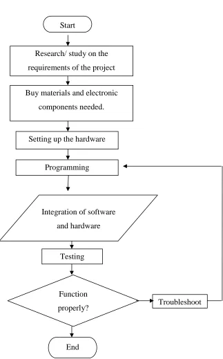
1.5 Methodology
To implement the execution of the project, a flow chart will be used to have an
overview of the top down approach to construct the project step by step. For any
problems that might surface, an iterative method is used to troubleshoot the project until
the project can finally function properly. Below is the flow chart that will be used to
5
[image:23.595.194.517.138.657.2]1.5.1 Methodology Flow Chart
Figure 1.1: The flow chart of methodology Research/ study on the
requirements of the project
Buy materials and electronic
components needed.
Setting up the hardware
Programming
Integration of software
and hardware
Testing
Function
properly?
End
6
1.6 PSM Report Overview
In brief, the report will contain 5 main chapters that will present the overall
progress from the main idea to design and representing the results of the project. At the
end, a conclusion will be made based on the findings after the completion of the project.
Suggestions will be added along this chapter to provide ideas on how to make the design
even better. Hence, the main contents of the report will be as the following:
i. Chapter 1: Introduction
ii. Chapter 2: Literature Review
iii. Chapter 3: Methodology
iv. Chapter 4: Result And Discussion
v. Chapter 5: Conclusion And Discussion