GRAPHIC EQUALIZER AND POWER AMPLIFIER
CHE MUNIRA BT CHE RAZALI
This Report Is Submitted In Partial Fulfillment of Requirements for the Bachelor of Electronic Engineering with Honours (Industrial Electronic)
Fakulti Kejuruteraan Elektronik Dan Kejuruteraan Komputer Universiti Teknikal Malaysia Melaka
UNIVERSTI TEKNIKAL MALAYSIA MELAKA
FAKULTI KEJURUTERAAN ELEKTRONIK DAN KEJURUTERAAN KOMPUTER
BORANG PENGESAHAN STATUS LAPORAN PROJEK SARJANA MUDA II
Tajuk Projek : GRAPHIC EQUALIZER AND POWER AMPLIFIER Sesi
Pengajian : 2006/2007
Saya CHE MUNIRA BT CHE RAZALI
(HURUF BESAR)
mengaku membenarkan Laporan Projek Sarjana Muda ini disimpan di Perpustakaan dengan syarat-syarat kegunaan seperti berikut:
1. Laporan adalah hakmilik Universiti Teknikal Malaysia Melaka.
2. Perpustakaan dibenarkan membuat salinan untuk tujuan pengajian sahaja.
3. Perpustakaan dibenarkan membuat salinan laporan ini sebagai bahan pertukaran antara institusi pengajian tinggi.
4. Sila tandakan ( √ ) :
SULIT*
(Mengandungi maklumat yang berdarjah keselamatan atau kepentingan Malaysia seperti yang termaktub di dalam AKTA RAHSIA RASMI 1972)
TERHAD* (Mengandungi maklumat terhad yang telah ditentukan oleh organisasi/badan di mana penyelidikan dijalankan)
TIDAK TERHAD
Disahkan oleh:
__________________________ ___________________________________
(TANDATANGAN PENULIS) (COP DAN TANDATANGAN PENYELIA)
Alamat Tetap: Batu 15 ½ Kg Bukit Bator,
16300 Bachok, Kelantan
iii
“I confess this report is all my own work except the certain passage that I have clarified each of their sources.”
iv
“I confess that I have read this report and for my opinion I think this report is sufficed in partial fulfillment of requirements for the Bachelor of Electronic
Engineering with Honors (Industrial Electronic)”
v
Special dedicated to my beloved family who always beside me the entire of my life
vi
ACKNOWLEDGEMENT
vii
ABSTRACT
Commercial audio amplifiers are now technologically advanced. An audio amplifier system consists of subsystems such as pre amplifier, graphic equalizer and power amplifier.
This part of project is to design, and constructs a graphic equalizer and power amplifier suitable for used in such an audio amplifier system.
The graphic equalizer is a circuit for adjusting the tonal quality of the audio signal that passes through it. For this project a 6 band graphic equalizer was designed and constructed.
viii
ABSTRAK
Penguat sistem audio komersial dengan reka cipta teknologi terkini amat canggih. Ianya dilengkapi dengan pelbagai subsistem seperti pra penguat, pengimbang bunyi grafik, penguat kuasa, dan litar pengurangan bunyi hingar.
Projek ini adalah bertujuan untuk merekabentuk sebuah pengimbang bunyi grafik dan penguat kuasa yang terdapat dalam sistem penguat audio. Kedua-dua peralatan ini bertujuan untuk mengolah dan menukar gelombang keluaran dan mengeluarkan bunyi seperti yang dikehendaki oleh pengguna.
Pegimbang bunyi grafik adalah litar yang digunakan untuk mengubah frekuensi audio mengikut kehendak pengguna. Setiap frekuenci yang diubah akan menghasilkan bunyi yang berbeza dari system penguat audio. Bagi projek ini 6 penapis frekuensi jalur direkabentuk sebagai satu pengimbang bunyi grafik. Litar pengimbang bunyi ini diuji, dianalsis dan dibina.
Penguat kuasa pula adalah litar yang digunakan untuk membesarkan isyarat keluaran dan membolehkan bunyi yang kuat dihasilkan. Penguat kuasa yang direkabentuk juga adalah sesuai untuk mengeluarkan isyarat keluaran yang sesuai untuk dikendalikan oleh alat pembesar suara 8 Ω.
ix
CONTENTS
CHAPTER TITLE PAGE
TITLE OF PROJECT i
PENGESAHAN STATUS LAPORAN ii
STUDENT CONFESSION iii
SUPERVISOR APPROVAL iv
DEDICATION v
ACKNOWLEDGMENT vi
ABSTRACT vii
ABSTRAK viii
CONTENTS ix
LIST OF FIGURE xii
LIST OF TABLE xiv
LIST OF ABBREVIATION xv
LIST OF APPENDIX xvi
I INTRODUCTION
1.0 PROBLEM STATEMENT 1
1.1 THE AUDIO AMPLIFIER 1
x
1.3 SURROUND SYSTEM FOR AUDIO 12
1.4 OBJECTIVES 14
1.5 SCOPE OF WORK 15
1.6 PROJECT METHODOLOGY 15 1.6.1 Hardware Specification 16 1.6 REPORT ORGANIZATION 18
II GRAPHIC EQUALIZER
2.0 GENERAL DESCRIPTION AND CONCEPT 19 2.1 THE GRAPHIC EQUALIZER SYSTEM 20 2.2GRAPHIC EQUALIZER PARAMETER 22 2.3 SIX BAND GRAPHIC EQUALIZER 23 2.4 CONSTRUCTION AND PCB LAYOUT 26 2.4.1 Component Selection 28 2.6 FREQUENCY RESPONSE AND CIRCUIT
OPERATION
29
III POWER AMPLIFIER
3.0 INTRODUCTION OF POWER AMPLIFIER 32 3.1 POWER AMPLIFIER BASIC OPERATION 32 3.2 POWER AMPLIFIER CLASS 34 3.3 POWER AMPLIFIER CHARACTERISTIC 38 3.4 MAXIMUM POWER TRANSFER THEORY
AND EFFICIENCY
40
3.5 POWER AMPLIFIER CONTRUCTION 41
xi
IV RESULT ANALYSIS
4.0 INTRODUCTION 44
4.1 SIMULATION, TESTING AND ANALYSIS 6 BAND GRAPHIC EQUALIZER
44
4.1.1 Circuit Testing 46 4.2 TESTING AND ANALYSIS OF POWER
AMPLIFIER
49
V DISCUSSION AND CONCLUSION
5.0 DISCUSSION 52
5.1 SUGGESTION AND IMPLEMENTATION 53
5.2 CONCLUSION 54
REFERENCES 55
xii
LIST OF FIGURE
NO TITLE PAGE
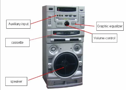
1.1 Audio amplifier system 3
1.2 Block diagram audio amplifier system 4 1.3 Block diagram audio amplifier design 15 2.1 10 band graphic equalizer 20 2.2 Graphic equalizer responses characteristic 21 2.3 Equivalent circuit that used for mathematical analysis
for each band equalizer
24
2.4 PCB layout 6 band graphic equalizer 27
2.5 PCB component layout 27
2.7 Equivalent circuit of equalizer at maximum boost 29 2.8 Frequency response at maximum boost 30 2.9 Equivalent circuit of equalizer at maximum cut 30 2.10 Frequency response at maximum cut 31 3.1 Block diagram for power amplifier operation 34 3.2 Equivalent circuit for IC STK 4141 II 42
4.1 Pspice simulation result 45
xiii
4.7 Setup for power amplifier circuit testing 49 4.8 Input voltage for power amplifier circuit at frequency
1kHz
50
4.9 Output voltage for power amplifier circuit at frequency 1kHz
50
xiv
LIST OF TABLE
NO TITLE PAGE
xv
LIST OF ABREVIATIONS
IC Integrated circuit
CD Compact disk
FET Field effect transistor
MOSFETS Metal-oxide-semiconductor field effect
transistor
dB Decibel
DVD Digital video decoder
Hz Hertz
AC Alternative current
DC Direct current
DTS Digital theater system
EQ equalizer
DPL Digital pro logic
PCB Printed circuit board
xvi
LIST OF APPENDIX
NO TITLE PAGE
A DATA SHEET STK 4141 II 56
B DATA SHEET TL 084 59
C CIRCUIT CONSTRUCTION 71
D SCHEMATIC DIAGRAM 74
CHAPTER I
INTRODUCTION
1.0 PROBLEM STATEMENT
An audio amplifier is a necessity to our everyday life. It has become a tool for entertainment and relaxation. Audio amplifiers are used in computer systems, home music systems, home theater systems and for amplifying sounds from musical instruments such as guitar, organ and other computer related instruments.
Because of this a reliable high fidelity audio amplifier should be made easily available. Commercial amplifiers are technologically advanced. Knowledge into the design of such an amplifier should be emphasized. The overall aim of this project is to study and design an audio amplifier system
1.1 THE AUDIO AMPLIFIER
2
The preceding stages in such a chain are low power audio amplifiers which perform tasks like pre-amplification. Equalization, tone control, mixing/effects, or audio sources like record players, CD players, and cassette players. Most audio amplifiers require these low-level inputs to adhere to levels.
Early audio amplifiers were based on vacuum tubes also known as valves. Most modern audio amplifiers are based on solid state devices like transistors, FETs and MOSFETs, but there are still efficient who prefer tube based amplifiers, as they have a 'warmer' sound due to a more linear V/I curve characteristic. Audio amplifiers based on transistors became practical with the wide availability of inexpensive transistors in the late 1960s.
In the new era, the digital circuits have been leading the way. From this more modification are being introduced and implemented. By taking many advantages from the digital circuits, designers are trying to design more sophisticated and better audio amplifier. Old analog control is being replaced by the powerful digital control system progressively. Nowadays, audio amplifier systems come out with many outstanding features, specifications and performance. Dolby noise reduction circuit has been incorporated to achieve superior signal to noise ratio, graphic equalizer for frequencies compensation and surround sound system for better stereo imagination and reality. Additional functions such as karaoke, mixer, sing along, benchmark of singing are provided in certain audio amplifier depends on its application.
3
Figure 1 Audio amplifiers system
4
1.2 OPERATION OF THE AUDIO AMPLIFIER
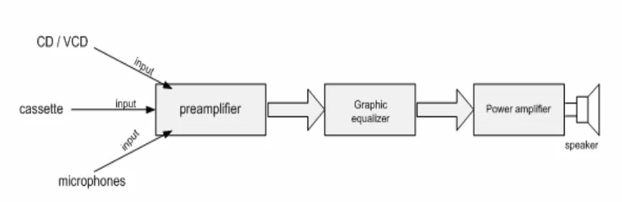
[image:20.612.119.558.194.337.2]The general purpose of design amplifier is to amplify the signal output from signal input through speaker. The block diagram below show basic audio amplifier system:
Figure 1.2 Block diagram for audio amplifier system
Refer to figure 1.1, the block diagram show a subsystem in an audio amplifier system. The function of pre amplifier is to boost signal to graphic equalizer. After that, the graphic equalizer controls the signal by adjusting the frequency response. A power amplifier was function to increase the strength of the audio signal from graphic equalizer through the loud speaker. The speaker is function to convert audio signal to sound.
The terms amplify basically means to make stronger. The strength of a signal (in terms of voltage) is referred to as amplitude. There are 3 types of amplification for amplifier:
• Voltage amplifier- an amplifier that boosts the voltage of an input signal • Current amplifier- an amplifier that boosts the current of a signal
5
Key design parameters for audio amplifiers are frequency response, gain, noise, and distortion. These are interdependent, increasing gain often leads to undesirable increases in noise and distortion. While negative feedback actually reduces the gain, it also reduces noise, and distortion.
1.2.1 General characteristic of amplifier i) Power gain
The gain is the ratio of output power to input power, and is usually measured in decibels (dB). (When measured in decibels it is logarithmically related to the power ratio: G (dB) =10log (Pout/Pin)).
ii) Output dynamic range
Output dynamic range is the range, usually given in dB, between the smallest and largest useful output levels. Since the lowest useful level is limited by output noise, this is quoted as the amplifier dynamic range.
iii) Bandwidth and rise time
The bandwidth (BW) of an amplifier is usually defined as the difference between the lower and upper half power points. This is therefore also known as the −3 dB BW. Bandwidths for other response tolerances are sometimes quoted (−1 dB, −6 dB etc.). The rise time of an amplifier is the time taken for the output to change from 10% to 90% of its final level when driven by a step input.
iv) Settling time
6
v) Slew rate
Slew rate is the maximum rate of change of output variable, usually quoted in volts per second (or microsecond).
vi) Noise
This is a measure of how much noise is introduced in the amplification process. Noise is an undesirable but inevitable product of the electronic devices and components. It is measured in either decibels or the peak output voltage produced by the amplifier when no signal is applied
vii) Efficiency
Efficiency is a measure of how much of the input power is usefully applied to the amplifier's output. The efficiency of the amplifier limits the amount of total power output that is usefully available. Note that more efficient amplifiers run much cooler, and often do not need any fans even in multi-kilowatt designs.
viii) Linearity
An ideal amplifier would be a totally linear device, but real amplifiers are only linear within certain practical limits. When the signal drive to the amplifier is increased, the output also increases until a point is reached where some part of the amplifier becomes saturated and cannot produce any more output; this is called clipping, and results in distortion.
7
1.2.2 Audio Amplifier Controls
These fall into a variety of categories:
Gain controls needed to adjust the signal level between source and power amplifier stages
Tone control used to modify the tone characteristic of the signal chain
Filters employed to remove unwanted parts of the incoming signal, and those adjustments used to alter the quality of the audio presentation, such as stereo channel balance or channel separation control
1.2.2.1 Improving High fidelity
Digital-to-digital transmission technology
Clearly high-resolution sounds (multi-channel and 2-channel) from DVD-Audio and SACD have enhanced the realism of listening to music at home. But some of the fine details are lost in the digital-to-analogue conversion and subsequent analogue transfer from the player to the amplifier, where possibly an additional analogue-to-digital conversion is performed for extended digital signal processing. Now, the VSA-AX10i-S includes the very latest I. LINK interface, the new industry standard for digital-to-digital audio transmission. Paired with a specialized ‘Mercury’ chipset co-developed with Texas Instruments Inc., I. LINK supports device-to-device digital audio data transfers including operational commands. With pure digital transfer where without data loss we will hear information from recordings as never before. Simply stated, this advanced digital audio processing translates into one digital cable instead of multiple analogue cables. I. LINK-equipped component, for example a DVD-Audio/Video/SACD player, to handle multi-channel DVD-Audio and SACD discs, not to mention digital audio from DVD-Video and CD, in all compressed and uncompressed formats for the first time in the entire history of audio amplifier.
8
Professional-quality 32-Bit Digital Signal Processing
It uses 32-bit Sharc and 24-bit double precision where it is equivalent to 48-bit Motorola DSP engines, such as those found in pro audio equipment. These devices process the data with extreme precision, enhancing multi-channel sound decoding and processing.
Ideal DVD Audio Converter
Highly accurate 96 kHz/24-bit A/D converters on all eight channels individually to precisely reproduce DVD-Audio and SACD sound sources when using players with 6-channel analogue outputs. For two-channel analogue sources, four A/D converters are used for each channel. This ensures truly superb 2-channel stereo reproduction for the very best high fidelity performance. Of course, directly routing the analogue input to the power amplifier is equally possible.
Innovative Frame Design Concept For Superior Support
This revolutionary chassis design fixes all parts to a 3-D frame instead of the weaker 2-D frame. So the unit has the strength to support the 10 kg transformer, as well as allow optimum functionality of each part. In addition, the chassis is copper-plated to suppress signal interference between circuits and reduce impedance.
Concentrated Direct Construction Design
To minimize signal interference, each circuit is separated – allowing a more direct signal route. This concentrated direct construction works simultaneously with the 3-D space frame to create an extremely pure signal transmission with an open and fresh sound.
Easy Connection And Simple Conversion