Frequency Support using Doubly Fed Induction and
1Reluctance Wind Turbine Generators
2A. B. Attyaa, S. Ademib,∗, M. Jovanovi´cc, O. Anaya-Larad
3
aDepartment of Electronic and Electrical Eng., University of Huddersfield, Huddersfield, UK
4
bWarwick Manufacturing Group, University of Warwick, Coventry, UK
5
cFaculty of Engineering and Environment, Northumbria University, Newcastle, UK
6
dDepartment of Electronic and Electrical Engineering, University of Strathclyde, Glasgow, U.K.
7
Abstract
8
This paper presents the comparative computer simulations of a commercial
doubly-9
fed induction generator (DFIG) and an emerging brushless doubly-fed reluctance
10
generator (BDFRG) for grid-connected wind turbines in terms of frequency
sup-11
port based on the inertia emulation and blade pitching de-loading. The BDFRG
12
features the low operation and maintenance cost by using a fractional inverter, and
13
offers the high reliability of brushless structure with a simpler, more compact
2-14
stage gearbox design whilst still ensuring competitive performance to its popular
15
slip-ring companion. The implemented benchmark is carefully designed to
as-16
certain the relative capabilities of the two wind turbine generator technologies in
17
providing this ancillary service. The results reveal that in spite of the
fundamen-18
tally different operating principles, the DFIG and the BDFRG are highly aligned
19
from the viewpoint of power system applications.
20
Keywords: Wind Power, Doubly-Fed Machines, Ancillary Services, Frequency
21
Stability, Virtual Inertia.
22
23
Nomenclature
24
DF De-loading ratio
25
Hd On-line inertia constant
26
fdropmax Full support frequency threshold 27
flow Frequency safe margin
28
fo Nominal frequency
29
Pc Actual conventional generation in AC area
30
Po
c Installed conventional generation in AC area
31
PW F Wind farm generation
32
Po
ref Active power reference
33
Te,m Wind turbine electrical, mechanical torque
34
Tgen Conventional generation torque
35
Trefo Nominal reference torque
36
Dg, Dl Dynamic load model parameters
37
J Moment of inertia
38
Kex Extraction factor
39
R Droop of aggregate generator
40
∆P Power mismatch
41
BDFG Brushless Doubly-Fed Generator
42
BDFIG Brushless Doubly-Fed Induction Generator
43
BDFRG Brushless Doubly-Fed Reluctance Generator
44
DFIG Doubly-Fed Induction Generator
45
DFMs Doubly-Fed Machines
KE Kinetic Energy
47
MPT Maximum Power Tracking
48
SGs Synchronous Generators
49
RoCoF Rate of Change of Frequency
50
TSOs Transmission System Operators
51
WFs Wind Farms
52
WS Wind Speed
53
WTGs Wind Turbine Generators
54
1. Introduction
55
The foreseen proliferation of distributed generation, and the accompanying
56
disconnection of conventional power plants, might seriously threaten the power
57
system voltage and frequency stability [1, 2]. Consequently, TSOs have been
58
updating the grid codes to incorporate the new demands from classical SGs and
59
WFs, while the manufacturers of WTGs are competing to assure the compliance
60
of their products with the latest grid integration regulations, including the
abil-61
ity to participate in the frequency regulation [3]. The reduced global inertia is a
62
critical challenge for the system stability to face with the increasing penetration of
63
WFs in large power networks or island grids [4] [5]. To this extent, several control
64
methods have been proposed with an incentive to allow the WTG to successfully
65
tackle the frequency decay by imitating the inertia and primary responses of SGs
66
in power stations [3, 4].Clear and well defined technical and legal rules and
proto-67
cols are essential to avoid possible conflicts and malfunctions when such support
methods are applied to large scale to ensure a smooth coordination between power
69
systems and WFs during and shortly after frequency events [6].
70
This can be accomplished by maintaining a certain power reserve, or by
re-71
leasing a portion of the stored KE in the WTG rotational parts [7]. The standard
72
approaches taken are turbine blades pitching (e.g. de-loaded operation), emulated
73
KE extraction (i.e. synthetic inertia), and tip-speed control [8]. Alternative
inno-74
vative strategies have also been devised and studied recently [9]. The effectiveness
75
of all these procedures is contingent upon the WTG responses to sudden changes
76
in WS and/or torque (power) reference stipulated by the controller to produce the
77
aimed power surge and help curtail the incurred frequency fluctuations in the best
78
possible manner. Quantitative metrics of frequency support capabilities of various
79
WTGs and WFs using different methodologies have been put forward in [10].
80
Some recent work touched upon the impact of the controllers gains to
pro-81
vide pitch de-loading and virtual inertia. The study derived the root-loci and
82
produced time simulations of a wide range of the involved controllers
parame-83
ters (e.g. pitching system, torque control and frequency support) to investigate
84
whether the control system stability was aligned to the improved performance of
85
frequency response [11]. The main challenges facing de-loading and KE
extrac-86
tion are continuous curtailment of wind power and post-event recovery
respec-87
tively. The amount of non-supplied energy due to de-loading techniques could be
88
estimated according to the expected load curtailments. These curtailments will
89
have an evident impact on frequency response as well as the financial aspects of
90
system operation and dispatching. Simplified mathematical representation of the
91
power system could be applied to calculate analytically the system inertia and
92
available primary reserve of WFs [12]. Meanwhile, the recovery stage (i.e. post
frequency drops declared clear) could trigger further frequency drops, as the WTG
94
output is suddenly reduced to start the recovery process, which is a key challenge
95
of KE extraction. This could be mitigated by applying a pre-set shaping function
96
with a ramp reduction in the WTG electrical output. The shaping function was
97
triggered automatically independent of the drop severity when the frequency
vi-98
olated the safe deadband to initiate a step increase in the reference power signal
99
of the WTG [13]. The technology and research challenges classification in
con-100
sidered six main categories of exploitation: frequency deadband, RoCoF, droop
101
control, de-loading parameters, wind turbine level and wind farm-wide. However,
102
the generator technology was not included which identify this area as a knowledge
103
gap that could be tackled by this paper. The same reference has also presented the
104
common designs of the supplementary controls used to apply the different
con-105
cepts of frequency support, and their integrative approach to the holistic controls
106
of the WTG [14].
107
The distinct advantages of high torque density, typically 30% rated power
elec-108
tronics, and inherently decoupled power control, have made the DFIG a widely
109
adopted cost-effective solution for multi-MW wind turbines with restricted
vari-110
able speed ranges (e.g. 2:1 or so) [15]. Nevertheless, the presence of brush gear
111
unavoidably reduces its reliability raising the maintenance requirements,
espe-112
cially off-shore [16]. The BDFG overcomes the above DFIG drawbacks and has
113
been regarded as a viable replacement. Unlike the DFIG, the BDFG has two
ordi-114
nary, distributed 3-phase stator windings of different applied frequencies and pole
115
numbers, and a rotor with half the total number of stator poles for the shaft
posi-116
tion dependent magnetic coupling to occur between the windings, a pre-requisite
117
for the torque production. The rotor can be of special ‘nested-loop’ cage or wound
structure (e.g. BDFIG) [17], featuring rather complicated and strongly parameter
119
reliant control, or modern cage-less reluctance form (e.g. BDFRG) [18] allowing
120
similar control simplifications of DFIG [15]. The primary (power) winding is
di-121
rectly grid connected, while the secondary (control) winding is supplied through a
122
fractional dual-bridge converter in ‘back-to-back’ configuration for bi-directional
123
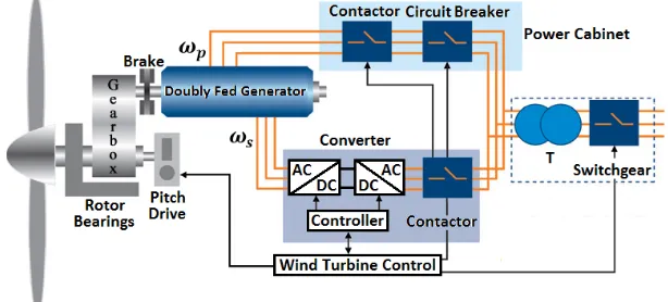
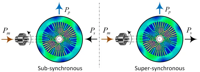
power flow as with the DFIG (Fig. 1).
[image:6.612.151.458.264.403.2]124
Figure 1: A generic conceptual diagram of the BDFG and DFIG wind turbine for adjustable speed constant frequency grid-connected applications2.
As the BDFG name reiterates, brushes and slip rings are eradicated, hence
125
a more robust and maintenance-free construction. Besides, the BDFG is
essen-126
tially a medium-speed machine, which renders the vulnerable high-speed stage
127
of a three-step planetary DFIG gearbox redundant, enhancing the reliability and
128
bringing further economic benefits [16]. These favorable properties are
partic-129
ularly appealing for off-shore WFs, where the DFIG running costs can be
con-130
siderable [19]. Moreover, another salient BDFG merit to be pointed out is the
131
distinguishing low-voltage-ride-through (LVRT) capability, which can be realised
132
with much facilitated, or completely without, protective crowbar circuitry for the
133
machine-side converter unlike the DFIG. Such attractive BDFG attributes have
been afforded by the proportionally higher leakage inductances and lower fault
135
current amplitudes than the equivalent DFIG having the well-known difficulties
136
to fully satisfy the LVRT pertaining grid codes [19].
137
Similar research to that conducted for the DFIG [15] has been carried out
138
on the BDFRG involving: vector control with voltage [20] or flux (field)
space-139
vector orientation [21] including sensorless operation since an encoder is required
140
for current control in a rotating frame, even though purely sensorless field oriented
141
control is feasible as documented in [22] using the maximum torque per inverter
142
ampere objective. The encoder-less BDFRG operation under power factor field
143
oriented control conditions, as an extension of this experimental vector control
144
research, has been elaborated in [23], direct torque [24] and power control [25].
145
Despite the apparent efforts and significant progress made in this direction, apart
146
from the aforementioned large-scale design studies [26], predominantly
small-147
scale laboratory prototyping has been the focus of attention among investigators,
148
except for the more sizeable BDFRGs reported in [27] and the latest one
elabo-149
rated in [17]. Although the BDFRG has been experimentally proven competitive
150
with the DFIG concerning both cost and performance [28], there is very little
151
documented on its grid integration issues and literally nothing published on the
152
feasibility to assist in the power system frequency control. Instead, the
exist-153
ing literature on the subject has mainly concentrated on the established industrial
154
technologies used for this purpose, the traditional DFIG [29] and/or the
perma-155
nent magnet generator [30]. However, publications on comparative analyses of
156
frequency support potential of these two, or any other WTGs are scarce [31].
157
2The control winding is on the stator for the BDFG, and on the rotor for the DFIG, but this is
Although the concepts of KE extraction and output de-loading are widely
dis-158
cussed in the literature, the proposed implementation methods are different where
159
the droop de-loading is applied to manipulate linearly to the instantaneous
fre-160
quency deviation. Likewise, the KE extraction is implemented through the tuning
161
of an over-demand parameter, which influences the ratio between optimum and
ac-162
tual torque references. The adopted methods and parameters settings are aligned
163
to enable a reasonable and fair comparison between the impacts of both the WTG
164
technology and the support methods. The key parameters in both methods are
165
selected to be equivalent, such that the de-loading and extraction factors are equal
166
and both controllers have the same frequency deadband and frequency drop limit
167
to release the full reserve. The applied case studies are also designed to consider
168
and emphasize the impact of WS changes either on the dynamics of the WTG
169
or the response of the power system, where the load dynamics are incorporated
170
to cause fine variations on the system frequency. This examines the reactions of
171
the WTG under like-real frequency oscillations when applying different
combina-172
tions of two different generator technologies and two frequency support methods.
173
The exploitation of these aspects is very limited in the literature. Finally, this
174
paper presents a simplified method to estimate the dynamic inertia of the power
175
system under the penetration of wind power. Consequently, this paper will
there-176
fore contemplate on the comparisons of the prominent and forthcoming BDFRG,
177
and the prevailing DFIG capacities to provide such an important ancillary service
178
operating as MW range WTGs.
2. BDFRG Model and Operating Aspects
180
The fundamental angular velocity and mechanical power relationships for the
electro-mechanical energy conversion in the machine, showing individual
contri-butions of each winding and assuming motoring convention as default, can be
written as follows [32, 33]:
ωr =
ωp+ωs pr
= ωp pr
·(1 + ωs ωp
) =ωsyn·(1 + ωs ωp
) (1)
Pm =Te·ωr =
Te·ωp pr
| {z }
Pp
+ Te·ωs pr
| {z }
Ps
=Ps·(1 + ωp ωs
) (2)
k = ωmax ωmin
= ωp+ ∆ωs ωp−∆ωs
=⇒∆ωs= k−1
k+ 1 ·ωp (3)
where ωsyn = ωp/pr [rad/s] is obtained for ωs = 0 i.e. a DC secondary as
181
with a 2pr-pole wound field synchronous turbo-machine, ωs > 0 for
‘super-182
synchronous’ operation, and ωs < 0 (e.g. an opposite phase sequence of the
183
secondary to the primary winding) in ‘sub-synchronous’ mode. Therefore, for
184
the same number of rotor poles, the synchronous speed (ωsyn) of the BDFRG is
185
half that of the DFIG, which implies that the 3rd stage of a gearbox, prone to
186
high failure rates and hence expensive repairs (foremost at sea), can be avoided
187
improving the reliability and reducing the WTG downtime as well as the
mainte-188
nance costs [16]. In the BDFRG case, Te < 0and thusPp < 0in (2), so that the
189
positive power is actually fed to the grid by the primary winding as expected in
190
the generating mode, while the secondary power (Ps) flow can be bi-directional
191
subject to the operating speed region as depicted in Fig. 2. Note also that if the
192
desired operating speed range is 2:1 i.e. ±∆ωs/pr aroundωsyn, being common
193
for WTGs, thenk = 2in (3) and the maximum secondary frequency turns out to
Figure 2: Reference directions of real power flow in the BDFRG windings for the operation below and above the synchronous speed.
be ∆ωs = ωp/3 whereasPs = Pm/4 according to (2). This means that only a
195
25% rated converter would be ideally needed as with the DFIG wind turbines.
196
The BDFRG dynamic and steady-state models in adp −qp frame for theωp
197
rotating primary winding space-vectors, and a ds −qs frame for the ωs rotating
198
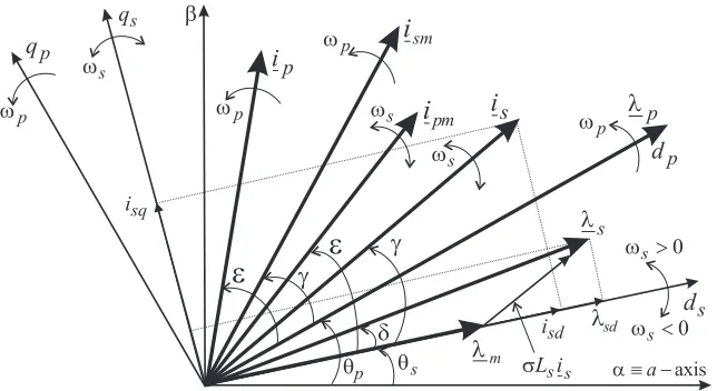
secondary counterparts (Fig. 3) can be represented as [20–23, 34]:
199
vp =Rpip+
dλp
dt =Rpip+jωpλp
vs =Rsis+
dλs
dt =Rsis+jωsλs
λp =Lp(ipd+jipq)
| {z }
ip
+Lm(ismd −jismq)
| {z }
i∗sm
λs =Ls(isd+jisq)
| {z }
is
+Lm(ipmd −jipmq)
| {z }
i∗pm
Figure 3: Characteristic space vectors and flux-oriented reference frames relevant for the BDFRG dynamic modelling and control.
The flux equations of (4) can be manipulated as [20–23, 34]:
λp =Lpipd+Lmismd
| {z }
λpd
+j·(Lpipq−Lmismq)
| {z }
λpq
(5)
λs =σLsisd+λmd
| {z }
λsd
+j·(σLsisq+λmq)
| {z }
λsq
=σLsis+ Lm
Lp λ∗p
| {z }
λm
(6)
where λm is the primary flux coupling the secondary winding, Lp,s,m are the
3-201
phase self and mutual inductances derived in [32, 33],σ = 1−L2m/(LpLs)is the
202
leakage factor, ism is the magnetically coupled (magnetizing) secondary current
203
vector (is) of the same magnitude but modulated frequency (i.e. ism = is in the
204
respective frames), and vice-versa for ipm = ip as shown in Fig. 3. Notice that
205
ism,ipandλpin (4) and (5) are in theωp frame, whereasis,ipmandλmin (4) and
206
(6) are in the prωrm −ωp = ωs frame given (1). This frame selection is termed
207
as ‘natural’ since the correspondingdqvector components become DC, which are
easier to control. The remaining dynamic modeling and operating principles of
209
the BDFRG are detailed in [32, 33].
210
It is interesting that regardless of the unconventional machine design, entirely
211
different basic theory and unusual torque producing mechanism [32, 33], the
BD-212
FRG model described by (4)-(6) in many respects resembles that for the DFIG
213
[15]. In fact, the BDFRG primary and secondary windings, and the associated
214
quantities, play the roles of the DFIG stator and rotor equivalents, respectively.
215
However, the awkward parameter referencing (Fig. 3) and other pertinent
struc-216
tural complexities make the BDFRG model much more challenging to implement
217
and simulate. In addition, the intrinsically modest magnetic coupling (e.g. higher
218
σvalues) may compromise the BDFRG transient response to some extent relative
219
to DFIG.
220
3. Frequency Support Methods and Operation
221
3.1. Pitch Droop De-loading 222
This technique can either be applied as Delta de-loading, when the WTG
out-223
put is de-rated continuously with a fixed relative ratio from the available power, or
224
Balance de-loading where an immobile margin between the MPT operation (e.g.
225
without frequency regulation) and the actual outputs is kept throughout to specify
226
the de-rating profile of interest [35]. This section is concerned with the
implemen-227
tation of the Delta concept in which the reference pitch angle is varied to maintain
228
a predetermined de-loading ratio (DF) and preserve the nominal rotor speed for
229
a given WS. The active power reference (Prefo ) is decreased by the required DF
230
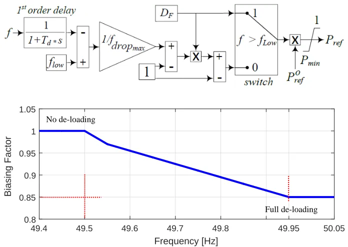
according to Fig. 4, and the latter is curtailed regularly through a droop gain until
231
the frequency drop reaches a predefined threshold (fdropmax), as illustrated by the
supplementary controller design in Fig. 4. For example, when the frequency
vio-233
lates a certain lower limit (flow), the WTG output could be as depicted, whereDF
234
= 15%,fdropmax = 49.5 Hz, andflow = 49.95 Hz.
49.4 49.5 49.6 49.7 49.8 49.95 50.05
Frequency [Hz] 0.8
0.85 0.9 0.95 1 1.05
Biasing Factor
[image:13.612.131.479.198.445.2]Full de-loading No de-loading
Figure 4: Supplementary controller diagram and curtailment pattern of per unit de-loading based on the incident frequency drop.
235
Such a procedure smoothens the frequency response and mimics the
gover-236
nor droop behaviour of conventional SGs. The de-loading is deactivated at higher
237
WSs, when the WTG delivers its rated power to mitigate the lost energy. However,
238
pitching is normally enabled to keep the WTG output and the rotor speed within
239
the acceptable limits, but at frequency incidents, the pitch angle can be reduced
240
to allow a temporary WTG overload, which must be compliant with the
manufac-241
turer specifications to avoid excessive over-heating or other potentially damaging
242
circumstances for the machine [8].
3.2. Kinetic Energy Extraction 244
This approach may be a preferable choice since it does not imply any energy
245
losses for the normal MPT operation of WFs without frequency control. However,
246
for the same WS, the power surge is lower compared to the de-loading method,
247
and there is also high susceptibility to WS conditions both during and after the
248
frequency event. The scheme relies on the rise of reference torque (Tref) beyond
249
its nominal value (Trefo ). Hence, the higher electrical demand than the available
250
mechanical input forces the WTG to extract some of its KE in order to secure the
251
necessary power support. The extraction factor (Kex) is governed by the severity
252
of the frequency drop through a droop response by analogy to the de-loading
253
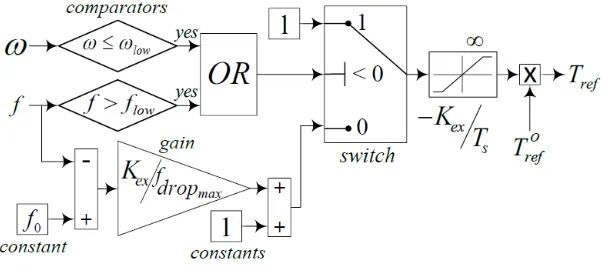
[image:14.612.155.456.374.507.2]method (1 ≤ Kex ≤ 1.15) as shown in Fig. 5. The KE extraction process halts
Figure 5: Subsidiary controller schematic of the KE extraction method. 254
when the rotor speed (ω) reaches a predefined lower threshold (ωlow). This method
255
is disabled in case of severe WS drops, which are unlikely to happen, as there
256
is no back-up source of energy to maintain the supportive power surge, and it
257
also puts the WTG under the risk of complete halt. The post-event stage is also
258
critical where the WTG accelerates to recover the nominal rotor speed, implying
259
a reference torque that is less than the nominal value.
3.3. WTG Modeling and Control 261
The auxiliary control algorithms from Figs. 4 and 5 are incorporated into the
262
realistic detailed DFIG (Type 3) NRELr model from the Simulinkr library as
263
outlined in Fig. 6 [36]. The replica dynamic model for an equally rated BDFRG
264
with independent real and reactive power control similar to DFIG [20, 34], and an
265
optimised ‘ducted’ rotor design (Fig. 2) [18, 26, 37], has been built by employing
266
the same GEr wind turbine so that useful comparative performance evaluations
267
[image:15.612.108.499.312.430.2]of the two WTG technologies can be made.
Figure 6: A generic block diagram of the upgraded NRELrWTG model [36] with the integrated supplementary frequency controllers.
268
The developed supplementary controllers are also suitably configured to
al-269
low a fair comparison between the underlying frequency support concepts using
270
the measured frequency input signals to trigger control actions. Furthermore, the
271
other key parameters in both methods are likewise selected to be identical for
ei-272
ther WTG. For example, the de-loading and extraction factors are equal, and both
273
controllers have the same frequency drop dead-bands and limits to release the
274
full reserve. The WTG specifications and per-unit values used for the simulation
275
analyses are summarised in Table 1.
Table 1: The parameters of the DFIG and BDFRG wind turbines
Parameter DFIG BDFRG
Rated power (MW) 1.5 1.5
Line voltage (V), frequency (Hz) 690, 50 690, 50
Rated speed (rev/min) 1800 600
Stator, rotor poles 4, 4 8/4, 6
Power winding resistance (pu) 0.0073 0.022
Power winding leakage inductance (pu) 0.1766 0.2519
Control winding resistance (pu) 0.0052 0.0446
Control winding leakage inductance (pu) 0.1610 1.1021
Magnetizing (mutual) inductance (pu) 2.9913 4.4084
Rated wind speed (m/s) 13 13
Gearbox stages/ratio 3/90 2/30
Drive-train inertia constant (s) 4.74 5.2
Note, however, that while the frequency regulation strategies under
considera-277
tion have been intensively investigated and applied in the literature [38], whereby
278
the corresponding implementation procedures used in this paper are inevitably
279
different when the droop de-loading ratio is manipulated in response to the
fre-280
quency deviation as shown in Fig. 4. Besides, the KE extraction is achieved by
281
appropriate tuning of the over-demand parameter (Kexin Fig. 5), which influences
282
the ratio between the optimum and actual torque references.
283
4. Studies of Wind Speed Effects
284
The following subsections examine a frequency scenario for step-changes of
285
average WS and realistic wind profiles, and the response of the proposed methods
286
and machines to a certain frequency test signal. The WS fluctuating nature is a
major challenge facing wind energy as a provider of frequency support, hence it is
288
important to exploit its impact when WS changes while the WTG/WF is
provid-289
ing frequency support. The impact of WS is also relevant to the comprehensive
290
comparison between the two machines where the input mechanical power changes
291
according to incident WS. Moreover, the proposed controls have certain modes of
292
operation to mitigate the negative influence of WS steep drops on the provided
293
support. Therefore, this paper tests the proposed methods and machines under a
294
steep WS drop simultaneously with a frequency event. In this section, a test
fre-295
quency signal is applied to the controls of the WTG, where the frequency drops
296
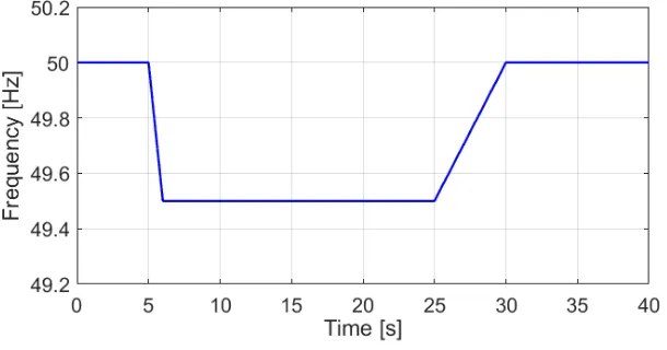
[image:17.612.153.458.377.537.2]by fdropmax = 0.5 Hz from its nominal value (fo) linearly within 1 s as shown in 297
Fig. 7, which means that the RoCoF is -0.5 Hz/s.
Figure 7:The applied frequency test signal complementary to Fig. 8 and Fig. 9.
298
This is inspired by the common requirements of grid codes [39]. Afterwards,
299
at t = 25 s the frequency gradually recovers to its nominal value with a rate of
300
change of 0.1 Hz/s. Thus, the WTGs response to frequency dips, and not minor
301
oscillations caused by mild load variations, is one of the main concerns of this
work. In order to enable better capturing of the WTG dynamics even under
tur-303
bulent winds, the sampling rate of 1 s is chosen for the applied intermittent WS
304
conditions.
305
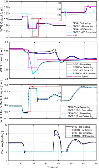
4.1. Step Responses 306
Two sudden WS changes are initiated at t = 15 s (e.g. from 8.2 m/s to 7.1 m/s)
307
and t = 22 s (e.g. a rise of 0.5 m/s). The power waveforms in Fig. 8 confirm that
308
the normal (i.e. no frequency event) WTG output is reduced in case of the
de-309
loaded method, while the KE extraction counterpart follows the MPT trajectory
310
providing a sustained power surge. The worst power dip occurs after the stored
311
KE is exhausted with the WTG speed reaching its lower threshold as in Fig. 8.
312
The zoomed image frames are integrated to the main figures to enhance the
visu-313
alization of some reflective dynamics in order to evidence the differences between
314
the waveforms amongst the two WTGs without compromising the visuals of the
315
full simulation span.
316
The WS drop makes the WTGs to temporarily divert away from the nearly
317
nominal speed as illustrated in Fig. 8. During the frequency recovery, it takes
318
about 25 s for the WTGs to regain the inceptive steady-state conditions due to
319
the inertia of the rotating masses, and the increasing pitch angles required to
re-320
store the de-loaded operation. On the contrary, the KE extraction method does not
321
imply such long transients with relatively high speed deviations for modest WS
322
fluctuations, mainly because the pitch angle is not deployed. The speed recovery
323
relies on the WS prior to the support provision and the attained drift during the
324
frequency event, where it reaches 0.63 pu. In spite of the continuous variations in
325
the available wind power, which are largely dictated by the WTG aerodynamics
326
and rotor speed controllers, the electrical torque (Te) accurately follows the
chanical (Tm). A quick torque response to the very steep change induced by the
328
sudden WS reduction is noticeable from the respective sub-plot in Fig. 8. It is also
329
visible that a generally good matching of the torque waveforms is slightly better
330
for the BDFRG, while the WTGs experience minor oscillations before reaching a
331
new steady-state point with the de-loading method being applied.
332
The results in Fig. 8 suggest a very close overall performance of the two
333
WTGs, the BDFRG exhibiting a marginally slower response when the pitch angle
334
is recovering to its non-zero value after the frequency transient. This is
mani-335
fested through the WTG speed under the de-loading method, and it is believed to
336
predominantly come from the somewhat higher inertia of the BDFRG drive train.
337
To achieve the DFIG de-loading level, a lower pitch angle is needed for the
BD-338
FRG (e.g. the respective peak values are ≈ 7◦ and 10◦), which may count as a
339
merit since the mechanical stresses exerted on the pitching mechanism should be
340
reduced as much as possible.
341
In summary, the sustainability of the WTG output under the KE extraction
342
method conditions is highly related to the initial WS and the WTG inertia.
Con-343
versely, the de-loading strategy does not imply any recovery periods, but the
out-344
put reduction process is naturally smooth via pitch control effects. In addition, the
345
applied droop pattern ensures the return to the normal de-loaded operation without
346
negative implications.
347
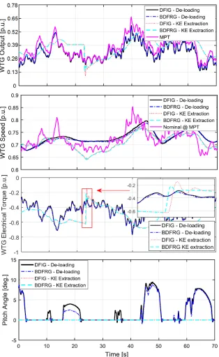
4.2. Natural Wind Speed Profile 348
True WS measurement data with an average of about 8 m/s are used to
inves-349
tigate the comparative WTGs performance under the intermittent WS conditions.
350
The WTG output characteristics presented in Fig. 9 are generally sub-optimal for
351
the de-loading method, however, the desired de-loading ratio is not fully achieved
as the pitch controller is not able to track all the intended WS fluctuations.
Imple-353
menting the support method makes the WTG to attain the available MPT output.
354
The KE extraction technique has proven capable of providing sustainable support
355
(but with a lower magnitude compared to the de-loading method at medium and
356
high WSs) as highlighted in Fig. 9. The additional power surge is kept constant
357
until the depletion of the stored KE stops to avoid the WTG deceleration,
evi-358
denced by the decreasing speed plots in the same figure, due to the imbalance
359
between the turbine (Tm) and generator (Te) torque. The amount of supportive
en-360
ergy is higher than with the de-loading method, because the WS drop emphasises
361
the benefit of the KE extraction approach. The intermittent WS profile screens the
362
dynamics of both machines, hence their very similar responses. It is also shown
363
that a large inertia and slow responses curtail the WTG ability to match the
op-364
timum rotor speed for a given WS at each time step. However, the deceleration
365
impact caused by the KE extraction method is evident during the frequency
tran-366
sient and as a consequence the WTG attempts to maintain a fixed power surge
367
according to Figs. 4 and 5.
368
The results in Fig. 9 of comparing theTevariations of the two generator
tech-369
nologies and the two support methods reflect the minor deviations between the
370
two generators. However, when the WTG reaches the threshold rotor low speed
371
which halts the KE exctraction process, the DFIG experiences a sharper transient
372
response compared to BDFRG, which is further clarified through the employed
373
zoom in frame. It can be also noticed the steeper tranisents in case of droop pitch
374
de-loading compared to KE extraction method due to the continous variations of
375
reference pitch angle to maintain the required de-loading ratio. Meanwhile, the
376
responses for either WTG are nearly overlapping. The pitch angle dynamics
firms that the de-loading exerts higher stresses on the WTG pitching system than
378
the KE extraction method, which does not require any additional pitching and
379
where at an average WS, the pitch angle is zero at all times. The BDFRG ensures
380
slightly reduced pitch angle changes than the DFIG by analogy to the previous
381
case study in Section 4.1.
382
5. Analysis of Power System Frequency Response
383
The considered benchmark is composed of an aggregate synchronous area and
installed conventional generation capacity (Po
c) feeding a composite load as shown
in Fig. 10. The AC area inclusion is intended to adequately represent a medium
scale power network with an average vulnerability to the frequency fluctuations,
which can be modelled as [29]:
˙
f = Pc+PW F −PL−(f−fo)·(Dl+ 4Dgf π
2)
4J f π2 (7)
˙ Pc=
Po
c ·[Loading−(f −fo)/(Rfo)]−Pc Tgen
(8)
where Pc and PW F are the actual conventional and wind power generation,
re-384
spectively, PL is the total main load andLoading (e.g. 95% ofPco in this paper)
385
signifies the Pc output set-point under normal (pre-event) operating conditions
386
(i.e. 5.32 GW), whereasfo is the nominal grid frequency (e.g. 50-Hz). The wind
387
installed capacity is assumed to be 35% ofPcowith a 50% WF capacity factor.
388
The WF is represented by an aggregate WTG of an equivalent capacity of
389
the WF, and facing a unified WS pattern. This does not compromise the level
390
of details of the applied test system as the aggregate models include the
essen-391
tial electromechanical components of the wind energy system. This aggregation
Figure 10: Conceptual representation of the implemented benchmark.
approach is used to achieve relatively high penetration level of wind power into
393
the test power system avoiding the additional computational efforts to model and
394
simulate each wind turbine and its incident wind speed separately. The remaining
395
model specifications are enlisted in Table 2. To retain consistency throughout the
396
paper authors have opted that the inertia constant in these units to comply with the
397
detailed modelling of the synchronous AC area which is described in (7) and (8),
398
thus inertia of the system in seconds is analysed in the next section.
Table 2: The parameters of the aggregate synchronous area
Conventional generation capacity (Po
c) 5.6 GW
Generation time constant (Tgen) 2 s
Lumped moment of inertia (J) 0.39 M.kg.m2
Generation droop (R) 0.06
Damping ratio (Dg) 95
Load frequency sensitivity ratio (Dl) 1%
399
The system dynamic inertia constant (Hd) is estimated during the critical
400
stages of the frequency event using the following expression:
401
Hd = fo
2 ˙f ·
∆P Pc+PW F
(9)
providing that f˙ ≤ −0.1 Hz/s and f < fo with ∆P denoting the instantaneous
403
mismatch between generation and demand. The dynamic inertia is actually the
in-404
ertia constant of the system captured at different time points during the frequency
405
event. The system inertia under high penetration of wind energy is highly variable,
406
so it is indicative to analyse the impact of WFs a provider of frequency support
407
on system inertia including the turbine WTG technology and the adopted support
408
method. This confirms the reasonable and expansive nature of the presented study
409
in this paper, where (Hd) is calculated using (9) given that the system frequency is
410
outside the deadband and experiencing a high rate of decay of 0.2 Hz/s or worse.
411
5.1. Considered Operating Scenarios 412
In each of the five case studies being examined, the system has suffered a
seri-413
ous frequency drop caused by a sudden loss of 12% of the conventional generation
414
capacity, namely 672 MW at t = 10 s time instant. The lost generation is gradually
415
recovered at t = 40 s with a gradient of 2% per second to mimic the secondary
re-416
sponse of SGs, and to test the compatibility of the applied support methods when
417
the frequency rebounds to the safe margin. In order to isolate the effects of the
418
support method and the type of machine, the WS is assumed constant at around
419
8 m/s during the frequency event. This assumption is acceptable because the
fre-420
quency transients should normally last no more than 10-30 s according to most
421
grid codes [3]. Over such a short interval, and due to the heavy WTG inertia,
422
many studies are based on the average WS conditions [40].
423
5.2. Results and Discussions 424
Fig. 11 shows that the frequency nadir has improved by about 0.25 Hz for the
425
de-loading method and 0.15 Hz for the KE extraction counterpart. It can also be
seen that the superior performance can be achieved with the de-loading approach
427
as the down-pitching recaps the higher output for a power surge compared to the
428
extracted energy at the selectedKex. The frequency excursion clearance after the
429
recovery of the lost generation is smooth without any spikes or overshoots due
430
to the developed droop controller action, which regulates the supportive power
431
surge through the droop constants (i.e. DF andKex) based on the frequency drop
432
severity. It is worth mentioning that the provided WF support reduces the RoCoF
433
during the critical early stage of the event. This is important in order to avoid
434
any unnecessary tripping of the RoCoF relays of SGs if the pre-set threshold (e.g.
435
typically from 0.5 Hz/s to 1 Hz/s during the first 500 ms) is violated according to
436
the grid code [39].
437
Differences brought by the two WTGs are fairly small because of the
pre-438
dominant power system dynamics over the WTG mechanical and aerodynamics
439
effects. The WTG decelerates and recovers to the nominal speed at lower rates
440
using the BDFRG, which coincides with the results obtained in Section 3.
How-441
ever, the maximum rotor speed deviation from its nominal value does not exceed
442
2%. The BDFRG appears to be more resistant to speed changes in case of droop
443
de-loading, which counts as a merit in its own right.
444
The WTGs power surges are almost identical for the two methods. Still, the
445
DFIG appears to be advantageous in this sense as detailed in the zoomed window
446
of the power plot in Fig. 11. The WTG decelerates during the KE extraction until
447
reaching a lower speed, as depicted in Fig. 11, which corresponds to the incident
448
frequency variation given the predetermined value of Kex. In this case study,
449
the frequency drop is less than fdropmax, which helps the WTG not to attain the
450
minimum allowed rotor speed. Hence, the WTG continues to operate at the lower
speed without the need to recover until the frequency starts building up to reach
452
the safe margin. The power surge sustained for about 10 s, and the recovery to
453
the nominal speed was slower for the BDFRG. The de-loading technique shows a
454
little impact on the WTG speed due to the WTG aerodynamics, mostly during the
455
pitching down as a small portion of the injected power accelerates the WTG, this
456
being limited in the BDFRG case. On the other hand, the DFIG pitching is ahead
457
of the BDFRG’s as shown in Fig. 11.
458
The Hd changes during the considered frequency scenario are presented in
459
Fig. 12. It can be seen that the Hd estimates have somewhat increased in all
460
the cases. The BDFRG achieved an extended rise of about 0.4 s relative to the
461
DFIG, which could be explained by its slightly faster response to theTmvariations
462
through the pitching process. Generally, theHdimprovements are marginal (i.e.
463
0.1 s to 0.3 s) during the critical period from t = 10 s up to 17 s. The frequency
464
starts building up to its nominal value at t = 40 s (Fig. 11), when the inertia drops
465
by 0.15 s at t = 44 s as zoomed in the right-sided window of Fig. 12, which
466
may be attributed to the BDFRG slower rotor speed recovery and the extended
467
time required for the WTG to reach its nominal output for a given WS. Hence,
468
the power imbalance is diminished after a slight delay reflecting upon the Hd
469
reduction according to (9). However, the inertia drop is about 5% of the average
470
value (≈ 3s). In addition, the overall system inertia is reduced compared to the
471
early stage of the event (i.e. after t = 10 s).
472
Note thatHdis evaluated using (9), and denoted accordingly in Fig. 12, only
473
if there is a power mismatch (i.e. generation less than demand causing a negative
474
RoCoF). Else, when a Hdvalue is not displayed this implies an improvement as
475
illustrated for t∈[10-15] s, whereHd ≈4 s, while cases with frequency support
Figure 12: The system dynamic inertia constant during the early and recovery stages of the implied frequency event.
do not return a value. Conversely, at t ∈ [16-17] s, the KE extraction returns
477
a relatively lower Hd, mainly for the BDFRG as discussed above, and the case
478
without support does not give any value in this time interval.
479
The qualitative properties of the two WTGs in the context of frequency support
480
provision are summarised in Table 3.
481
Table 3: Relative advantages (+) and limitations (-) of the WTGs
Frequency Support Indicator DFIG BDFRG
De-loading pitch angle (-) Higher (+) Lower
KE extraction rotor speed recovery (+) Faster (-) Slower
Extractable KE (-) Less (+) More
Power system dynamic inertia (-) Reduced (+) Improved
6. Conclusions
482
This paper has made a comprehensive multi-dimensional comparison of two
483
frequency support methods, the KE extraction and pitch de-loading, individually
484
applied to the closely related WTG types, the conventional DFIG and evolving
[image:29.612.139.476.448.546.2]BDFRG. The major contributions of the work are therefore manifold and not only
486
limited to comparing the integrated generator technologies for a given frequency
487
regulation technique as its main focus, but also the other way around. The
consid-488
ered concepts have shown to play a pivotal role in the power injection during the
489
frequency transient and the WTG post-incident restoration of normal operation.
490
The KE extraction has allowed a somewhat faster DFIG recovery response than
491
BDFRG’s, while both WTGs are able to offer similar de-loading performance,
492
with slightly mitigated pitch angle variations in the BDFRG case, which are
fa-493
vorable to the pitch actuators.
494
The frequency studies have indicated discrepancies between the WTGs, that
495
largely depend on the ratio of the actual wind power penetration level to load
496
demand at the inception of frequency disturbance event and the support
method-497
ology in question. The dynamic inertia evaluation has confirmed the merit of pitch
498
de-loading approach by the absence of both adverse implications and reliance on
499
the drive train inertia. The results presented are encouraging and have
undoubt-500
edly shown that the BDFRG can be rather competitive with the commercial DFIG
501
of the same rating in terms of frequency support abilities to warrant further
inves-502
tigations as a promising brushless candidate for wind power applications.
503
References
504
[1] Y. Wang, G. Delille, H. Bayem, X. Guillaud, B. Francois, High wind power
505
penetration in isolated power systems - assessment of wind inertial and
pri-506
mary frequency responses, IEEE Trans. on Power Systems 28 (3) (2013)
507
2412–2420.
508
[2] H. Banakar, C. Luo, B. T. Ooi, Impacts of wind power minute-to-minute
variations on power system operation, IEEE Trans. on Power Systems 23 (1)
510
(2008) 150–160.
511
[3] F. Diaz-Gonzalez, M. Hau, A. Sumper, O. Gomis-Bellmunt, Participation of
512
wind power plants in system frequency control: Review of grid code
require-513
ments and control methods, Renew. and Sust. Energy Reviews 34 (2014)
514
551–564.
515
[4] M. Dreidy, H. Mokhlis, S. Mekhilef, Inertia response and frequency control
516
techniques for renewable energy sources: A review, Renewable and
Sustain-517
able Energy Reviews 69 (2017) 144–155.
518
[5] A. Attya, J. Dominguez-Garcia, O. Anaya-Lara, A review on frequency
sup-519
port provision by wind power plants: Current and future challenges, Renew.
520
and Sust. Energy Reviews 81 (2018) 2071 – 2087.
521
[6] A. D. Hansen, M. Altin, F. Iov, Provision of enhanced ancillary services from
522
wind power plants examples and challenges, Renewable Energy 97 (2016)
523
8 – 18.
524
[7] F. M. Hughes, O. Anaya-Lara, N. Jenkins, G. Strbac, Control of DFIG-based
525
wind generation for power network support, IEEE Transactions on Power
526
Systems 20 (4) (2005) 1958–1966.
527
[8] A. B. Attya, T. Hartkopf, Wind turbine contribution in frequency drop
mit-528
igation - modified operation and estimating released supportive energy, IET
529
Generation, Transmission Distribution 8 (5) (2014) 862–872.
530
[9] P. Tielens, D. V. Hertem, Receding horizon control of wind power to provide
531
frequency regulation, IEEE Trans. on Power Syst. 32 (4) (2017) 2663 – 2672.
[10] A. B. Attya, O. Anaya-Lara, W. E. Leithead, Novel metrics to quantify the
533
impacts of frequency support provision methods by wind power, in: IEEE
534
PES Innovative Smart Grid Tech. Conf. Europe, 2016, pp. 1–6.
535
[11] F. Wilches-Bernal, J. H. Chow, J. J. Sanchez-Gasca, A fundamental study of
536
applying wind turbines for power system frequency control, IEEE Trans. on
537
Power Syst. 31 (2) (2016) 1496–1505.
538
[12] F. Teng, G. Strbac, Assessment of the role and value of frequency response
539
support from wind plants, IEEE Trans. on Sust. Energy 7 (2016) 586–595.
540
[13] F. Hafiz, A. Abdennour, Optimal use of kinetic energy for the inertial support
541
from variable speed wind turbines, Renewable Energy 80 (2015) 629 – 643.
542
[14] A. Aziz, A. T. Oo, A. Stojcevski, Frequency regulation capabilities in wind
543
power plant, Sust. Energy Tech. and Assessments.
544
[15] R. Cardenas, R. Pena, S. Alepuz, G. Asher, Overview of control systems for
545
the operation of DFIGs in wind energy applications, IEEE Trans. on Ind.
546
Electron. 60 (7) (2013) 2776–2798.
547
[16] J. Carroll, A. McDonald, D. McMillan, Reliability comparison of wind
tur-548
bines with DFIG and PMG drive trains, IEEE Trans. on Energy Convers.
549
30 (2) (2015) 663–670.
550
[17] F. Zhang, S. Yu, X. Wang, H. Wang, S. Jin, Research of a novel brushless
551
doubly-fed generator with hybrid rotor, IEEE Trans. on Appl. Supercond.
552
26 (7) (2016) 1–5.
[18] A. Knight, R. Betz, D. Dorrell, Design and analysis of brushless doubly
554
fed reluctance machines, IEEE Transactions on Industry Applications 49 (1)
555
(2013) 50–58.
556
[19] M. Cheng, Y. Zhu, The state of the art of wind energy conversion systems
557
and technologies: A review, Energy Convers. and Manag. 88 (2014) 332–
558
347.
559
[20] S. Ademi, M. Jovanovic, Control of doubly-fed reluctance generators for
560
wind power applications, Renewable Energy 85 (2016) 171–180.
561
[21] S. Ademi, M. Jovanovi´c, Vector control methods for brushless doubly fed
562
reluctance machines, IEEE Transactions on Industrial Electronics 62 (1)
563
(2015) 96–104.
564
[22] S. Ademi, M. G. Jovanovi´c, H. Chaal, W. Cao, A new sensorless speed
con-565
trol scheme for doubly fed reluctance generators, IEEE Trans. on Energy
566
Conv. 31 (3) (2016) 993–1001.
567
[23] S. Ademi, M. Jovanovi´c, A novel sensorless speed controller design for
568
doubly-fed reluctance wind turbine generators, Energy Conversion and
Man-569
agement 120 (2016) 229–237.
570
[24] H. Chaal, M. Jovanovic, Toward a generic torque and reactive power
con-571
troller for doubly fed machines, IEEE Transactions on Power Electronics
572
27 (1) (2012) 113–121.
573
[25] M. Jovanovi´c, H. Chaal, Wind power applications of doubly-fed reluctance
574
generators with parameter-free hysteresis control, Energy Conversion and
575
Management 134 (2017) 399–409.
[26] D. G. Dorrell, M. Jovanovi´c, On the possibilities of using a brushless
doubly-577
fed reluctance generator in a 2 MW wind turbine, IEEE Industry
Applica-578
tions Society Annual Meeting (2008) 1–8.
579
[27] L. Xu, B. Guan, H. Liu, L. Gao, K. Tsai, Design and control of a
high-580
efficiency doubly-fed brushless machine for wind power generator
applica-581
tion, in: IEEE Energy Conversion Congress and Exp., 2010, pp. 2409–2416.
582
[28] W. Chen, Comparison of doubly-fed induction generator and brushless
583
doubly-fed reluctance generator for wind energy applications, Ph.D. thesis,
584
Newcastle University, UK (2014).
585
[29] S. Ghosh, S. Kamalasadan, N. Senroy, J. Enslin, Doubly fed induction
gen-586
erator (DFIG)-based wind farm control framework for primary frequency
587
and inertial response application, IEEE Trans. on Power Syst. 31 (3) (2016)
588
1861–1871.
589
[30] J. F. Conroy, R. Watson, Frequency response capability of full converter
590
wind turbine generators in comparison to conventional generation, IEEE
591
Trans. on Power Syst. 23 (2) (2008) 649–656.
592
[31] A. Mullane, M. O’Malley, The inertial response of induction-machine-based
593
wind turbines, IEEE Trans. on Power Syst. 20 (3) (2005) 1496–1503.
594
[32] M. G. Jovanovic, R. E. Betz, J. Yu, The use of doubly fed reluctance
ma-595
chines for large pumps and wind turbines, IEEE Trans. on Ind. Appl. 38
596
(2002) 1508–1516.
597
[33] R. E. Betz, M. G. Jovanovi´c, Introduction to the space vector modelling of
the brushless doubly-fed reluctance machine, Electric Power Components
599
and Systems 31 (8) (2003) 729–755.
600
[34] S. Ademi, M. Jovanovi´c, M. Hasan, Control of brushless doubly-fed
reluc-601
tance generators for wind energy conversion systems, IEEE Transactions on
602
Energy Conversion 30 (2) (2015) 596–604.
603
[35] I. D. Margaris, S. A. Papathanassiou, N. D. Hatziargyriou, A. D. Hansen,
604
P. Sorensen, Frequency control in autonomous power systems with high
605
wind power penetration, IEEE Trans. on Sust. Energy 3 (2) (2012) 189–199.
606
[36] M. Singh, E. Muljadi, J. Jonkman, Simulations for wind turbine generators
607
– with FAST and MATLAB-Simulink models, Tech. rep., National
Renew-608
able Energy Laboratory (NREL), U.S. Department of Energy (April 2014.
609
Available to download from: http://www.nrel.gov/docs/fy14osti/59195.pdf).
610
[37] D. Dorrell, A. Knight, R. Betz, Improvements in brushless doubly fed
reluc-611
tance generators using high-flux-density steels and selection of the correct
612
pole numbers, IEEE Trans. on Magnetics 47 (10) (2011) 4092–4095.
613
[38] H. Ye, W. Pei, Z. Qi, Analytical modeling of inertial and droop responses
614
from a wind farm for short-term frequency regulation in power systems,
615
IEEE Transactions on Power Systems 31 (5) (2016) 3414–3423.
616
[39] Rate of change of frequency (RoCoF) modification to the grid code, Tech.
617
rep., The Commission for Energy Regulation (May 2016).
618
[40] R. Doherty, A. Mullane, G. Nolan, D. J. Burke, A. Bryson, M. O’Malley, An
619
assessment of the impact of wind generation on system frequency control,
620
IEEE Transactions on Power Systems 25 (1) (2010) 452–460.
![Figure 6: A generic block diagram of the upgraded NREL® WTG model [36] with the integratedsupplementary frequency controllers.](https://thumb-us.123doks.com/thumbv2/123dok_us/1363522.89766/15.612.108.499.312.430/figure-generic-block-diagram-upgraded-integratedsupplementary-frequency-controllers.webp)