City, University of London Institutional Repository
Citation: Kovacevic, A. (2017). Application of numerical grid generation for improved CFD
analysis of multiphase screw machines. IOP Conference Series: Materials Science and Engineering, 232(012017), doi: 10.1088/1757-899X/232/1/012017This is the accepted version of the paper.
This version of the publication may differ from the final published
version.
Permanent repository link: http://openaccess.city.ac.uk/18566/
Link to published version: http://dx.doi.org/10.1088/1757-899X/232/1/012017
Copyright and reuse: City Research Online aims to make research
outputs of City, University of London available to a wider audience.
Copyright and Moral Rights remain with the author(s) and/or copyright
holders. URLs from City Research Online may be freely distributed and
linked to.
City Research Online: http://openaccess.city.ac.uk/ [email protected]
Application of numerical grid generation for improved CFD
analysis of multiphase screw machines
S Rane and A Kovačević
City, University of London, Centre for Compressor Technology, London, UK. Email: [email protected]
Abstract. Algebraic grid generation is widely used for discretization of the working domain of twin screw machines. Algebraic grid generation is fast and has good control over the placement of grid nodes. However, the desired qualities of grid which should be able to handle multiphase flows such as oil injection, may be difficult to achieve at times. In order to obtain fast solution of multiphase screw machines, it is important to further improve the quality and robustness of the computational grid. In this paper, a deforming grid of a twin screw machine is generated using algebraic transfinite interpolation to produce initial mesh upon which an elliptic partial differential equations (PDE) of the Poisson’s form is solved numerically to produce smooth final computational mesh. The quality of numerical cells and their distribution obtained by the differential method is greatly improved. In addition, a similar procedure was introduced to fully smoothen the transition of the partitioning rack curve between the rotors thus improving continuous movement of grid nodes and in turn improve robustness and speed of the Computational Fluid Dynamic (CFD) solver. Analysis of an oil injected twin screw compressor is presented to compare the improvements in grid quality factors in the regions of importance such as interlobe space, radial tip and the core of the rotor. The proposed method that combines algebraic and differential grid generation offer significant improvement in grid quality and robustness of numerical solution.
1
Introduction
compressors and pumps using differential methods. Reports on analysis of dry air screw compressors and twin screw expanders with real gas models are available in literature using these techniques [8]. Although several attempts have been made in the recent past to extend the CFD technology to oil injected compressors, it has proven to be difficult to achieve the desired grid structure and the modelling conditions that can provide stability to the numerical solvers. Kovačević and Rane have reported in [6] results from the analysis of a dry air expander and it was found that CFD models deviated in prediction of leakage flow much more under the operating condition of low rotor speed and higher pressure difference then at higher rotor speeds with low pressure difference. On the other hand, Rane et al in [9] analyzed a twin screw compressor and found that refinement of the rotor grid in circumferential direction has a direct influence on the prediction of the mass flow rate. Rane [10] proposed a new analytical approach for grid generation that can independently refine the interlobe region of the screw rotors. It was demonstrated that such grid refinement improves the prediction of mass flow rates. The same algebraic algorithm has been extended to produce a rotor grid that eliminates the interface between two rotors and thereby providing a desirable grid for oil injected or multiphase modelling.
In this paper, deforming grid of the twin screw machine is generated using these algebraic techniques and treated as an initial mesh upon which Elliptic PDE of the Poisson’s form is solved. The resulting differential grid has highly improved cell quality and distribution. In addition, a special procedure has been introduced that completely smooths the transition of the partitioning rack curve between the two rotors thus improving grid node movement and robustness of the CFD solver. A sample analysis of an oil injected twin screw compressor using the new Elliptic PDE grids has been presented to compare the improvements in grid quality factors in the regions of importance such as interlobe space, radial tip and core of the rotors. A significant improvement in the grid quality and robustness of numerical solver with higher order schemes has been obtained with this differential implementation of the deforming mesh.
2
Differential grid generation principle
In structured grid generation, techniques based on solutions of Partial Differential Equations to define coordinate transformation are widely used. The idea of using elliptic PDE like Laplace equation or Poisson equation is based on the work of Crowley [1] and Winslow [14]. Elliptic PDE’s have certain beneficial properties in their solution that make them preferable for body fitted curvilinear grids:
Extremum principle – It is possible to formulate PDE’s such that the extrema of their analytical solutions cannot be within the domain. Hence there are fewer tendencies for folding of mesh lines.
Inherent smoothness – The resulting coordinate curves in the interior are smooth and some discontinuities over the boundaries do not get propagated into the interior of the domains.
Boundary – The coordinate points on physical boundaries can be exactly specified as boundary conditions in the computational space.
[image:3.595.102.502.609.733.2]But the numerical grid generation is computationally expensive and preferably an initial grid based on algebraic methods needs to be prescribed in order for the required derivatives to be used efficiently for solution of PDE’s.
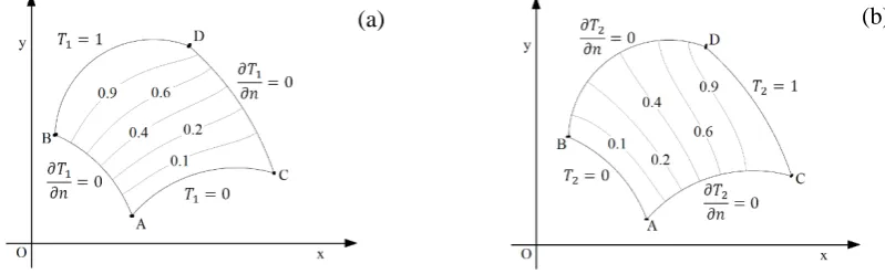
Figure 1. Differential construction of a 2D curvilinear grid.
Consider a 2D domain as shown in Figure 1. The region is bounded by four curves AB, BD, CD and AC. To demonstrate the principle, a heat conduction problem will be used with boundary conditions T1 and T2 as shown in Figure 1 a and b.
For domain (a)
𝜕𝜕2𝑇𝑇 1
𝜕𝜕𝑥𝑥2 +
𝜕𝜕2𝑇𝑇 1
𝜕𝜕𝑦𝑦2 =
𝑞𝑞"1
𝑘𝑘 ,
𝑇𝑇1= 0,𝑎𝑎𝑎𝑎𝐴𝐴𝐴𝐴𝑎𝑎𝑎𝑎𝑎𝑎𝑇𝑇1= 1,𝑎𝑎𝑎𝑎𝐵𝐵𝐵𝐵
𝜕𝜕𝑇𝑇1
𝜕𝜕𝑎𝑎 = 0, 𝐴𝐴𝐵𝐵𝑎𝑎𝑎𝑎𝑎𝑎𝐴𝐴𝐵𝐵
where 𝑎𝑎is the Normal to the boundary
(1)
Similarly for domain (b)
𝜕𝜕2𝑇𝑇 2
𝜕𝜕𝑥𝑥2 +
𝜕𝜕2𝑇𝑇 2
𝜕𝜕𝑦𝑦2 =
𝑞𝑞"2
𝑘𝑘 ,
𝑇𝑇2= 0,𝑎𝑎𝑎𝑎𝐴𝐴𝐵𝐵𝑎𝑎𝑎𝑎𝑎𝑎𝑇𝑇2= 1,𝑎𝑎𝑎𝑎𝐴𝐴𝐵𝐵
𝜕𝜕𝑇𝑇2
𝜕𝜕𝑎𝑎 = 0, 𝐴𝐴𝐴𝐴𝑎𝑎𝑎𝑎𝑎𝑎𝐵𝐵𝐵𝐵
(2)
The solution to systems (a) and (b) provides isotherms which can be written as
𝑇𝑇1=𝑇𝑇1(𝑥𝑥,𝑦𝑦), 𝑇𝑇2=𝑇𝑇2(𝑥𝑥,𝑦𝑦) (3)
Each isotherm 𝑇𝑇1 and 𝑇𝑇2thus represents a set of (𝑥𝑥,𝑦𝑦) and the two solutions get superimposed as a body-fitted curvilinear grid in the domain. Equation (1) and (2) can be re-written by interchanging roles of 𝑇𝑇 and (𝑥𝑥,𝑦𝑦), with correspondence of 𝑇𝑇1:ξ and𝑇𝑇2:η.
∇2ξ = 𝜕𝜕2ξ
𝜕𝜕𝑥𝑥2+
𝜕𝜕2ξ
𝜕𝜕𝑦𝑦2 = 𝑃𝑃(ξ,η),
∇2η = 𝜕𝜕2η
𝜕𝜕𝑥𝑥2+
𝜕𝜕2η
𝜕𝜕𝑦𝑦2 = 𝑄𝑄(ξ,η),
(4)
Where (ξ,η) are curvilinear coordinates and 𝑃𝑃(ξ,η) and 𝑄𝑄(ξ,η) are stretching functions and the system is a basic Poisson system of PDE. In order to determine Cartesian coordinates from equation (4) they must be inverted. The inverted equation in 2D reads as [2]:
∇2∅ = 1
J2 �𝛼𝛼
𝜕𝜕2∅
𝜕𝜕ξ2 −2𝛽𝛽 𝜕𝜕
2∅
𝜕𝜕ξ 𝜕𝜕η +𝛾𝛾 𝜕𝜕
2∅
𝜕𝜕η2�+𝑃𝑃
𝜕𝜕∅
𝜕𝜕ξ +𝑄𝑄𝜕𝜕𝜕𝜕ξ∅ (5)
Replacing ∅ by 𝑥𝑥 and y and ∇2𝑥𝑥=∇2𝑦𝑦= 0, 𝛼𝛼 𝜕𝜕2𝑥𝑥
𝜕𝜕ξ2−2𝛽𝛽
𝜕𝜕2𝑥𝑥
𝜕𝜕ξ 𝜕𝜕η +𝛾𝛾 𝜕𝜕
2𝑥𝑥
𝜕𝜕η2= −J2 �𝑃𝑃
𝜕𝜕𝑥𝑥
𝜕𝜕ξ +𝑄𝑄𝜕𝜕𝜕𝜕ξ𝑥𝑥� (6)
𝛼𝛼 𝜕𝜕2𝑦𝑦 𝜕𝜕ξ2−2𝛽𝛽
𝜕𝜕2𝑦𝑦
𝜕𝜕ξ 𝜕𝜕η +𝛾𝛾 𝜕𝜕
2𝑦𝑦
𝜕𝜕η2 = −J2 �𝑃𝑃
𝜕𝜕𝑦𝑦
𝜕𝜕ξ +𝑄𝑄𝜕𝜕𝜕𝜕ξ𝑦𝑦�
J =𝜕𝜕𝜕𝜕ξ𝑥𝑥 𝜕𝜕𝜕𝜕η𝑦𝑦 − 𝜕𝜕𝜕𝜕ξ𝑦𝑦 𝜕𝜕𝜕𝜕η𝑥𝑥 , α=��𝜕𝜕𝜕𝜕η𝑥𝑥�2 + �𝜕𝜕𝜕𝜕η𝑦𝑦�2�
β=�𝜕𝜕𝜕𝜕ξ𝑥𝑥 𝜕𝜕𝜕𝜕η𝑥𝑥 + 𝜕𝜕𝜕𝜕ξ𝑦𝑦 𝜕𝜕𝜕𝜕η𝑦𝑦� , γ=��𝜕𝜕𝜕𝜕ξ𝑥𝑥�2 + �𝜕𝜕𝜕𝜕ξ𝑦𝑦�2�
Equation (6) and (7) are coupled and nonlinear because of𝛼𝛼,𝛽𝛽𝑎𝑎𝑎𝑎𝑎𝑎γ. They are solved simultaneously using schemes like Tri-diagonal Matrix Algorithm. The boundary conditions as grid coordinates are specified atξ= 0,ξ=ξ𝑚𝑚𝑚𝑚𝑚𝑚𝑎𝑎𝑎𝑎𝑎𝑎η= 0,η=η𝑚𝑚𝑚𝑚𝑚𝑚. One of the difficulties with elliptic PDE’s is that at the boundary either Dirichlet or Neumann boundary conditions are required.
Thompson, Thames and Mastin [12] have proposed the following stretching function in order to control grid clustering.
𝑃𝑃(ξ,η) =− � 𝑎𝑎𝑛𝑛
𝑁𝑁
𝑛𝑛=1
(ξ−ξ𝑛𝑛)
�ξ−ξ𝑛𝑛�𝑒𝑒−𝑐𝑐𝑛𝑛�ξ−ξ𝑛𝑛� − � 𝑏𝑏𝑖𝑖
𝐼𝐼
𝑖𝑖=1
(ξ−ξ𝑖𝑖)
�ξ−ξ𝑖𝑖�𝑒𝑒−𝑑𝑑𝑖𝑖��
ξ−ξ𝑖𝑖�2+�η−η𝑖𝑖�2�1�2
(8)
𝑄𝑄(ξ,η) =− � 𝑎𝑎𝑛𝑛
𝑁𝑁
𝑛𝑛=1
(η−η𝑛𝑛)
�η−η𝑛𝑛�𝑒𝑒−𝑐𝑐𝑛𝑛�η−η𝑛𝑛� − � 𝑏𝑏𝑖𝑖
𝐼𝐼
𝑖𝑖=1
(η−η𝑖𝑖)
�η−η𝑖𝑖�𝑒𝑒−𝑑𝑑𝑖𝑖��ξ−ξ𝑖𝑖�
2
+�η−η𝑖𝑖�2�1�2 (9)
Here 𝑁𝑁 is the number of clustering grid lines (coordinate linesξ=ξ𝑛𝑛𝑎𝑎𝑎𝑎𝑎𝑎η=η𝑛𝑛 ) and 𝐼𝐼 is the number of clustering points (with ξ=ξ𝑖𝑖, η=η𝑖𝑖, 0≤ξ𝑖𝑖, η𝑖𝑖 ≤1 ) to which the grid is to be attracted. 𝑎𝑎𝑛𝑛, 𝑐𝑐𝑛𝑛, 𝑏𝑏𝑖𝑖𝑎𝑎𝑎𝑎𝑎𝑎𝑎𝑎𝑖𝑖are positive control parameters. The first term in 𝑃𝑃(ξ,η) has the effect with amplitude
𝑎𝑎𝑛𝑛 of attracting ξ− 𝑙𝑙𝑙𝑙𝑎𝑎𝑒𝑒𝑙𝑙towards curves ξ=ξ𝑛𝑛 in the physical domain, while the second term attracts
ξ− 𝑙𝑙𝑙𝑙𝑎𝑎𝑒𝑒𝑙𝑙 with amplitude 𝑏𝑏𝑖𝑖 towards points. Similarly the two terms in 𝑄𝑄(ξ,η) control the grid line spacing. In each case the attractive effect decays with the distance in the computational space from the lines or points according to the decay parameters𝑐𝑐𝑛𝑛𝑎𝑎𝑎𝑎𝑎𝑎𝑎𝑎𝑖𝑖.
The functions (ξ−ξ𝑛𝑛)
�ξ−ξ𝑛𝑛� 𝑎𝑎𝑎𝑎𝑎𝑎
(η−η𝑛𝑛)
�η−η𝑛𝑛� are function which can take only the value ±1 and ensure the
clustering to take place on both sides of ξ𝑛𝑛− 𝑙𝑙𝑙𝑙𝑎𝑎𝑒𝑒𝑙𝑙𝑎𝑎𝑎𝑎𝑎𝑎η𝑛𝑛− 𝑙𝑙𝑙𝑙𝑎𝑎𝑒𝑒𝑙𝑙. The amplitude can be set negative to turn attractive effects into repulsive ones.
3
Differential grid generation for twin screw rotor grids
Algebraic methods are convenient for quick adjustment and recalculation of the deforming grid. Kovačević et al [4], Kovačević [5], Kovačević and Rane [6] and Rane et al [9] have successfully used an algebraic grid generation method together with boundary adaptation and transfinite interpolation. Vande Voorde and Vierendeels [13] have implemented a grid conversion algorithm for unstructured to block structured mesh from solution of Laplace equation for twin screw compressors and pumps using the differential methods. Based on this grid generation, flow in a double tooth compressor and a twin screw compressor has been analyzed and the results have been compared with experimental data over a range of discharge pressure and rotor speeds. A detailed description of the algebraic grid generation for twin screw rotors can be found in Kovačević [5]. By use of a background blocking technique [10], the algebraic grid generation is able to produce a single domain structured grid for the twin rotor domains. With this algebraically generated single domain grid as an initial framework it is possible to solve the PDE system presented in Section 2 in order to produce a better quality differential mesh.
3.1 Initial Algebraic grid generation
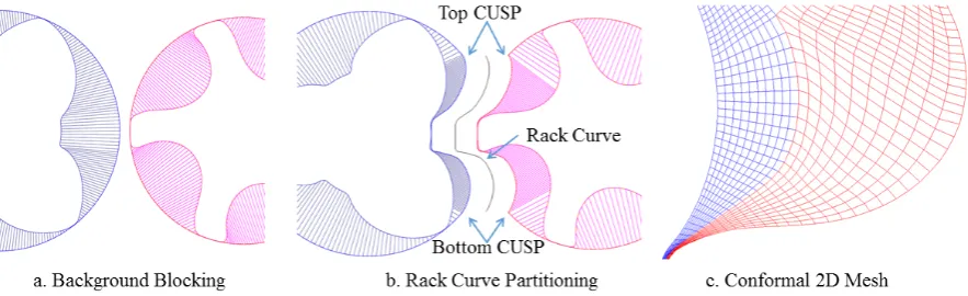
been presented in Rane [10]. In this procedure, outer boundary in each background block is defined as a combination of the rack segment and the casing circle segment. The rack segment stretches between the bottom and top cusp points and is closed by the casing. The distribution obtained on the outer boundaries of the two blocks is used as a reference for rotor profile distribution as shown in Figure 2a.
Figure 2. Background blocking for regular boundary discretization and conformal algebraic mesh.
Figure 2b shows how the rack curve is used to partition the two rotor domains and the boundary distribution so obtained is used to generate the 2D mesh using transfinite interpolation. Using the blocking approach allows both conformal and non-conformal boundary map to produce fully hexahedral 3D grid. Figure 2c shows the nodes on the rack segment between the main and the gate rotor grids with conformal boundary map. The 3D mesh generated from such 2D cross sections allows the rotor domains of the male and female rotors to be combined into a single rotor mesh. This avoids inaccuracies and instabilities that may arise due to the interface mismatch in non-conformal boundary map. The resultant grids are recommended for oil injected multiphase flow modelling. But during operation when the rotors turn further, the rack curve has to transition and the current algebraic methods have this transition as a step change at certain positions. One of the objectives of elliptic PDE mesh generation presented in this paper was to improve the time transition of the partitioning rack curve between the two rotor domains.
3.2 Applying the Elliptic PDE solver to improve algebraic grid
The treatment described in Section 2 for differential mesh generation requires the solution of the coupled PDE equations (6) and (7). Schemes like Tri-diagonal Matrix Algorithm can be used for the solution. The boundary conditions are specified as grid coordinates atξ= 0,ξ=ξ𝑚𝑚𝑚𝑚𝑚𝑚𝑎𝑎𝑎𝑎𝑎𝑎η= 0,η=η𝑚𝑚𝑚𝑚𝑚𝑚.
𝑃𝑃(ξ,η) = 0 (10)
𝑄𝑄(ξ,η) =−𝑄𝑄0𝑙𝑙𝑠𝑠𝑎𝑎(𝑟𝑟)𝑒𝑒−|𝑟𝑟| , 𝑟𝑟= (η−η
𝑠𝑠) 𝑎𝑎𝑎𝑎𝑎𝑎𝑙𝑙𝑠𝑠𝑎𝑎(𝑟𝑟) =
𝑟𝑟
|𝑟𝑟| (11)
differential solver are merged to produce a single domain mesh for the two rotors as seen in Figure 3 – Final PDE Mesh.
3.3 Smoothing the rack curve time transition to improve boundaries
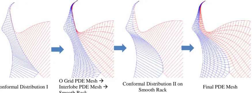
The PDE Mesher described in Section 3.2 is used in a selective interlobe area bounded by the top and bottom cusp radial nodes of the mesh to convert the rack curve into a smooth transitioning curve across the specified number of angular positions of the rotor. This results into a gradually changing partition between the two O grids of the male and female rotors as shown in Figure 3.
Conformal Distribution I
O Grid PDE Mesh Interlobe PDE Mesh Smooth Rack
Conformal Distribution II on
[image:7.595.83.521.224.387.2]Smooth Rack Final PDE Mesh
Figure 3. Four-step procedure for improving time transition of the rack curve.
[image:7.595.81.362.425.537.2]This smooth rack is then supplied back to a second stage of boundary distribution calculation resulting in a new conformal distribution. New conformal distribution is further used as boundary condition for final differential mesh generation. As a result a significant improvement in the mesh quality is achieved. Figure 4. Improvement in the 3D rack surface.
This four-step procedure is very quick and the time required for calculation of a representative 2D mesh with 5000 node count, across 50 rotor positions is less than 15 seconds. Figure 4 shows the smooth rack surface generated on the 3D mesh. The sharp sections observed with original surface (Initial algebraic mesh) are eliminated and a completely smooth surface deformation with time was achieved.
3.4 Meshing parameters for PDE Mesh generation
Meshing parameters listed in Table 1 are used to control the stretching functions of the Poisson system of the PDE mesh and SOR solver convergence. Smoothness of the conformal grid described in Section 3.3 also needs a control over the number of cells to smooth adjacent to the rack curve in the final 2D mesh. Using this control continuity can be achieved on the mesh lines and cell expansion factor can be improved by specifying a higher interlobe smoothing factor. Some examples of the outputs with different control factors are shown in Figure 5 (a-d). Figure 5a shows a grid generated by specifying a relaxation factor = 0. This produces a pure TFI based algebraic mesh with no smoothing and orthogonalisation.
Mesh Orthogonality and Smoothing Factor
Relaxation Factor Relaxation factor controls mesh orthogonalisation and smoothing by relaxing the increment in each consecutive iteration.
Tolerance Factor Convergence criteria for PDE solver. Inflation Layer Control
Radial Bias Factor - η𝒔𝒔 Factor is used to select boundary for bias. 1 – Rotor, 0 – Casing. Radial Bias Intensity - 𝑸𝑸𝟎𝟎 Intensity of stretching the nodes towards the boundaries.
Conformal Mesh Control
[image:8.595.72.524.116.339.2]Interlobe Smoothing Factor Factor is used to smooth layers of mesh adjacent to the rack.
Figure 5. Response of the PDE meshing parameters in a representative 2D section.
Figure 5b is a grid generated by a high relaxation factor = 1. In combination with a higher tolerance factor makes the grid lines smooth and the rack transition becomes gradual. Radial Bias Factor is used to control the stretching of nodes towards the boundaries. In Figure 5c with a Radial Bias Intensity = 2 and a Radial Bias Factor = 0.5, the radial nodes are pulled towards the rotor and the casing. The value of η𝒔𝒔can range from 0 to 1. 1 pulls nodes towards the rotor while 0 pulls the nodes towards casing. An intermediate value can thus be used to control the inflation layers in the rotor domain.
3.5 Improvement in grid quality
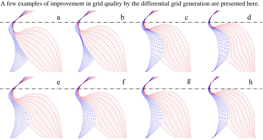
A few examples of improvement in grid quality by the differential grid generation are presented here.
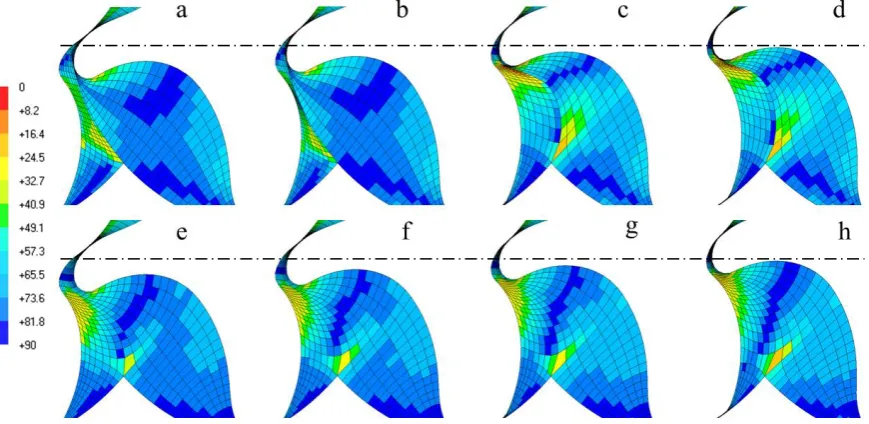
[image:8.595.70.524.473.714.2]Figure 6 shows a comparison of the grid and rack transition between algebraic and elliptic meshes. Figure 6 a-d are algebraic meshes for four successive rotor positions and Figure 6 e-h are the elliptic meshes for the respective rotor positions. Between position Figure 6b and c a sudden transition in the rack curve is noticeable. On the other hand, in the respective Figure 6f and g the rack node transition is gradually. Also Figure 6e and h highlight the characteristics of the elliptic mesh that the rack nodes in the earlier and next rotor positions were in smooth transition. Figure 6 e-h also show that the interior cell structures have improved and radial mesh lines between the two rotor domains have continuity.
Figure 7. Comparison of cell expansion factor between Algebraic (a) and Elliptic (b) meshing.
[image:9.595.106.482.209.358.2]Figure 7 a and b present a comparison of the cell expansion factor. Figure 7a corresponds to Figure 6b and Figure 7b corresponds to Figure 6f which are the positions just before rack transitions in the algebraic mesh. A high cell expansion factor of about 20 is seen in the algebraic mesh in this rotor position. In case of elliptic mesh, due to rack smoothing, the cell expansion factor is less than 3.6
Figure 8. Comparison of cell orthogonal quality between Algebraic (a-d) and Elliptic (e-f) meshing.
[image:9.595.80.515.446.658.2]quality and also the minimum value is not below 25 degree. Most of the cells are in the range of 75 – 90 degree. One particular cell at the bottom cusp shows low orthogonality of about 15 degree in both the algebraic and the elliptic mesh. This is mainly due to the abrupt topology change that happens at the cusp point.
4
Application of Elliptic grid for oil injected twin screw compressor analysis
Flow in an oil flooded twin screw compressor with a combined axial and radial suction and an axial discharge port was calculated with the new elliptic PDE grid. The male rotor has four lobes and the female rotor has five lobes with ‘N’ profiles. The nominal interlobe, radial and axial leakage gaps are 60 µm. The operating speed of the machine is between 3000 rpm and 6000 rpm, discharge pressure can vary between 4.0 bar and 12.0 bar. A complete description of the model numerical setup can be found in Rane et al [11].
4.1 Oil distribution inside the compression chamber
[image:10.595.78.527.376.521.2]The fluctuating nature of the oil injection was well captured by the CFD model. Figure 9 shows the distribution of oil and its interaction in the discharge port. Iso-surface of 10% oil volume fraction shows an accumulation of oil in the rotor tips and also high concentration on the discharge port walls. Similarly oil accumulates in the interlobe gaps and is transported forward by the rotors. The oil distribution pattern in the discharge port is highly unsteady but cyclically repeating.
Figure 9. Oil flow distribution near the discharge port.
Figure 10. Discharge gas temperature distribution at 6000rpm, 8.0bar pressure.
4.2 Temperature distribution
Figure 10 shows the distribution of air temperature in the domain at 8.0bar discharge pressure, 6000rpm with an iso-surface of 10% oil volume fraction. With built-in Vi of 3.6 for the machine, the adiabatic discharge temperature without oil injection would be about 500 K but due to leakages and recompression effects, the temperature rise would be much higher. Due the injected oil at 323 K, the gas temperature is substantially lowered and does not exceed 340 K. It can be seen that the local maximum temperature reaches to about 360 K. Also the gas temperature is not uniformly distributed. This non-uniformity is due to the non-homogeneous distribution of oil in the compression chamber.
5. CONCLUSIONS
using algebraic grid generation. This mesh is treated as the initial mesh upon which Elliptic PDE of the Poisson’s form is solved. The resulting grid has highly improved quality and distribution of computational cells. In addition, a special four-step procedure has been introduced that completely smoothens the transition of the algebraically generated partitioning rack curve between the two rotors thus smoothing the grid node movement in time and space. These grid features have improved the robustness of the solution in CFD solvers.
Analysis of an oil injected twin screw compressor is presented in order to compare the improvements in the grid quality factors in the regions of importance such as interlobe space, radial tip and core of the rotors. Significant improvement in the grid quality and robustness of numerical solver with higher order advection schemes has been obtained with this new deforming mesh. The results from the simulation provided an exceptional visualization of the interaction of gas and oil inside the compression chamber. The interaction of the phases, distribution of oil, heat transfer between gas and oil and also effects on sealing due to high oil concentration in leakage gaps were well captured.
Nomenclature
PDE - Partial Differential Equation 𝑞𝑞" - Heat flux
ξ,η - computational coordinate 𝑥𝑥,𝑦𝑦,𝑧𝑧 - Cartesian coordinates 𝑟𝑟,𝜃𝜃 - polar coordinates of a point 𝒓𝒓 - radius vector
𝑃𝑃(ξ,η) - Control function for x stretching 𝑄𝑄(ξ,η) - Control function for y stretching α,β,γ - Coefficients of elliptic PDE J - Transformation Jacobian Matrix
η𝑠𝑠 - Radial bias factor 𝑄𝑄0 - Radial bias intensity TFI - Transfinite Interpolation SOR - Successive over-relaxation
References
[1] Crowley W. P., 1962. An equipotential zoner on a quadrilateral mesh. Memo, Lawrence Livermore Lab. [2] Date W. A., 2005. Introduction to computational fluid dynamics. ISBN-10 0-521-85326-5. Cambridge
University Press.
[3] Knupp P. and Steinberg S., 2002. The Fundamentals of Grid Generation. ISBN 9780849389870. CRC Press.
[4] Kovačević A., Stošić N. and Smith I. K., 2007. Screw compressors - Three dimensional computational fluid dynamics and solid fluid interaction, ISBN 3-540-36302-5, Springer-Verlag New York.
[5] Kovačević A., 2002, Three-Dimensional Numerical Analysis for Flow Prediction in Positive Displacement Screw Machines, Thesis, City, University of London.
[6] Kovačević A. and Rane S., 2013. 3D CFD analysis of a twin screw expander, 8th International conference
on compressors and their systems, London, p. 417.
[7] Pascu M., Kovačević A. and Udo N., 2012. Performance Optimization of Screw Compressors Based on Numerical Investigation of the Flow Behaviour in the Discharge Chamber. Proc. Int. Compressor Conf. at Purdue. Paper 1145.
[8] Papes, I., Degroote, J. and Vierendeels, J., 2013, 3D CFD analysis of an oil injected twin screw expander. Pro of the ASME 2013 International Mechanical Engineering Congress and Exposition, San Diego, USA: ASME IMECE 2013.
[9] Rane S., Kovačević A., Stošić N. and Kethidi M., 2014. Deforming grid generation and CFD analysis of variable geometry screw compressors, Computers and Fluids, 99, p. 124–141.
[10] Rane, S., 2015. Grid Generation and CFD analysis of Variable Geometry Screw Machines, Thesis, City, University of London.
[11] Rane S., Kovačević A. and Stošić N., 2016. CFD Analysis of Oil Flooded Twin Screw Compressors. Proc. Int. Compressor Conf. at Purdue. Paper 2392. http://docs.lib.purdue.edu/icec/2392
[12] Thompson J. F., Thames F. C. and Mastin C. W., 1974. Automatic Numerical Generation of Body-Fitted curvilinear coordinate system for field containing any number of arbitrary two-dimensional bodies. J. Comput. Phys., vol. 15, pp. 299-319.
[13] Voorde Vande J., Vierendeels J., 2005. A grid manipulation algorithm for ALE calculations in screw compressors. 17th AIAA Computational Fluid Dynamics Conference, Canada, AIAA 2005-4701.