Moments
.
White Rose Research Online URL for this paper:
http://eprints.whiterose.ac.uk/115293/
Version: Accepted Version
Article:
Brüns, Heinz, Vogt, Alexander, Findeklee, Christian et al. (5 more authors) (Accepted:
2017) Modeling Challenging EMC Problems Using the Method of Moments.
Electromagnetic Compatibility Magazine, IEEE. ISSN 2162-2264 (In Press)
[email protected]
https://eprints.whiterose.ac.uk/
Reuse
Items deposited in White Rose Research Online are protected by copyright, with all rights reserved unless
indicated otherwise. They may be downloaded and/or printed for private study, or other acts as permitted by
national copyright laws. The publisher or other rights holders may allow further reproduction and re-use of
the full text version. This is indicated by the licence information on the White Rose Research Online record
for the item.
Takedown
If you consider content in White Rose Research Online to be in breach of UK law, please notify us by
Abstract—A variety of numerical techniques are used in electromagnetic compatibility (EMC) for the numerical analysis of practical problems. The most important are the finite-difference time-domain technique, the finite-element method, the transmission-line-matrix method and the method of moments. All approaches have their strengths and weaknesses and cannot be applied to all kinds of problems with the same degree of efficiency, measured in memory consumption and computation time necessary. In this paper it is shown that the method of moments (MoM) can be applied to a variety of scenarios, each of which would form a challenging problem to all of the mentioned numerical techniques. It is shown that a customization of the MoM to the specific problems at hand can be accomplished. All examples shown have been computed using the academic code CONCEPT-II developed at Hamburg University of Technology (TUHH).
Index Terms—Method of moments, lightning, radar cross section (RCS), numerical modeling, H-matrices, reverberation chamber, stochastic electromagnetic fields, magnetic resonance imaging (MRI), broadband antenna optimization.
I. INTRODUCTION
OWADAYS, numerical simulations are common-place in the daily work of an EMC engineer. Among the various techniques available the method of moments (MoM) [1, 2] has outstanding capabilities for the numerical analysis of a broad range of problems, encountered in the area of EMC. Traditionally, MoM is applied in the frequency domain. Especially for electrically large surface and/or wire structures it has advantages compared to other numerical approaches. Essentially, a radiating or scattering structure is replaced by equivalent currents, which are developed into line currents for wires and into surface currents in case of surfaces. Each of these currents is defined over electrically small neighboring segments (basis functions) and has an impact on all other surface and/or wire currents. Applying the underlying boundary condition leads to a set of linear equations expressed by a fully populated quadratic matrix with complex coefficients. Solving the corresponding equation system provides an approximation of the physical current distribution which in turn provides all quantities that might be of interest in electromagnetic engineering. MoM is one of the most widely applied numerical techniques in computational electromagnetics and has a long history since the original paper of Harrington was published. It is well known that the technique is quite sensitive to an appropriate discretization (surface patch grid), regarding both electrical size, shape, and geometrical complexity of the object under consideration. Hence, the user should have a good knowledge of the
underlying principles to quickly obtain accurate results. To demonstrate the capabilities of the numerical tech under discussion and to get more familiar with it contribution gives details about a series of selected num problems, which have been presented in a workshop h the EMC Europe conference in Dresden, August 2015. of CONCEPT-II [3] were asked to report on their exper and surprises they made while treating specific problems
this code. All examples presented showed
challenges not so well known in the EMC community result, a broad range of interesting applications, inc topics like dimensioning of magnetic resonance imaging testing of objects in reverberation chambers, radar section investigations or the analysis of direct lightning s could be demonstrated. The intention of this paper summarize what can be achieved with the MoM appropriate extensions thereof.
For several decades, CONCEPT-II has been continuous development at the Institute of Electroma
Modeling Challenging EMC Problems
Using the Method of Moments
Heinz-D. Brüns, Alexander Vogt, Member IEEE, Christian Findeklee, Member IEEE, Arne Schröder, Memb IEEE, Mathias Magdowski, Member IEEE, Martin Robinson, Member IEEE, Fridolin Heidler, Member IEEE
Christian Schuster, Senior Member IEEE
[image:2.595.429.591.195.438.2]N
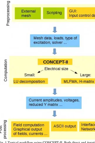
Theory at the Hamburg University of Technology (TUHH), Germany. The package is based on various types of integral equations in the frequency-domain. It is designed for the computation of currents, electromagnetic fields and secondary quantities in wire and surface structures consisting of both metallic sheets and lossy dielectric materials. Various types of excitations are available. Lumped loads and generators can be placed at arbitrary locations in the grid. The package is limited to linear materials which have to be homogeneous and isotropic in all regions. The application of the code is free of charge for academic institutions that want to use it in education or public research. During recent years, its core and graphical user interface have been re-implemented with a modern code structure which is necessary for incorporating future research work. Fig. 1 illustrates the possibilities that are currently implemented.
The examples demonstrated in the following sections are difficult to solve with a basic MoM implementation, i.e., special features and enhancements are needed to obtain the results. The specific challenges being addressed by the examples include:
stable solutions for highly resonant cavities,
extraction and postprocessing of multiport network parameters,
automated and fast computation of multiple excitations,
optimization of radiating structures,
efficient modeling of reverberation chamber environments, and
accurate representation of field excitations given by lightning strokes.
All challenges could be met with the CONCEPT-II code.
II. EMC ANALYSIS OFHIGHLYRESONANTPC CHASSIS
In the frequency domain, a boundary element method such as the MoM and the finite-element method (FEM) are good choices in general. It is common knowledge that MoM is particularly well suited for the analysis of problems with radiation into free space. On the other hand, for 3-D closed structures, FEM is considered to be the method of choice in many cases. In the following example it is demonstrated, that MoM is capable of solving a highly resonant cavity with internal excitation yielding excellent results.
[image:3.595.428.595.38.129.2]During the last decades, the compute power of personal computers (PCs) has constantly increased. With this, the clock frequencies of the PC components and especially the data busses have reached the GHz range. As a consequence, the components constitute good radiators. These effects need to be accurately considered in system level simulations when solutions to issues involving electromagnetic interference need to be solved.
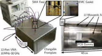
Fig. 2 Analyzed PC chassis: a rectangular chassis with the given dime is excited by twelve monopole probes on the walls. The interac measured by a network analyzer and calculated by MoM. The contains a dummy fixture resembling a typical PC mainboard with a extension cards. The figure has been adapted from [9], further details a exact locations are given there.
Time-domain methods have convergence problem highly resonant, low loss cavities. Nevertheless at frequencies, the dimensions of typical desktop workst are in the range of several wavelengths, which leads to a number of unknowns. This requires the utilization o solvers to reduce the solution time and the required me Unfortunately, iterative solvers such as the multileve multipole method (MLFMM) [5] converge slowly due high quality factor of the cavity. As a remedy, a fast solver based on H-Matrices has been implemented f CONCEPT-II package. The capability to additionally in lossy dielectric materials in the simulation makes this applicable to a wide range of problems as encountered PCs [10].
The main principle behind the H-matrix algorithm decomposition of far-interaction blocks in the system m into low-rank approximations [7]. The easiest way to this would be to perform a singular value decompo (SVD) of the far-interaction block. However, the SVD i costly and requires prior calculation of the complete m block. This limitation can be overcome by the adaptive approximation (ACA) [4], which directly calculates a rank approximation of the far-interaction Unfortunately, it is not known a priori by how far a m block can be reduced. In the worst case of incompre blocks, one would obtain two matrices of the same dime as the original block, with twice the memory requiremen an increased computational effort. Therefore, it is essen accurately predict the compressibility of matrix blocks a in CONCEPT-II. When a minimum block size is reache corresponding blocks are kept as full matrices. The res H-matrix consists of low-rank and full matrix blocks an either be inverted for a direct solution of the equation sy or used for an iterative solution [7].
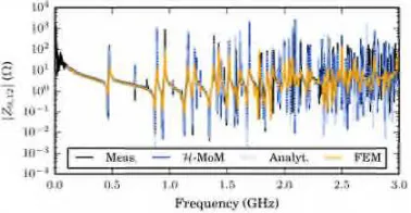
discretized as a flat homogeneous body. The front plate contains two horizontal and two vertical slots located at 1 cm away from the walls and extending almost along the complete height and width. In [9], the correlation between simulation and measurements has been reported to be excellent, see Fig. 3.
The chassis according to Fig. 2 is modeled with a triangular mesh using the open source toolgmsh[6] the output of which can conveniently be imported into CONCEPT-II. The internal short monopole antennas are modeled as thin strips with a width of twice the monopole diameter [8]. At a maximum frequency of 3 GHz, this results in a setup of approximately 30,000 unknowns for the empty chassis and 120,000
unknowns for the populated one. Here, the solution times have been reduced by a factor of ten to twenty over the considered frequency range compared with the traditional LU-decomposition technique. The simulation process required a few minutes per frequency point on a desktop workstation with 32 GB of RAM and an Intel CPU (i7-4930K, one core). Due to the reduced asymptotic complexity of the H-matrix algorithm in both simulation time and memory footprint, this benefit is more pronounced for larger simulation setups. The complete PC system with internal components and absorbing sheets present could be reduced to a relative matrix size of 3% compared to the full matrix. This enabled an analysis on a desktop machine. In this case, the simulation could be performed in less than an hour per frequency point.
III. MULTIPORTSOLUTIONMETHODS FORMAGNETIC
RESONANCEIMAGINGCOILS
The following structure is characterized by a resonant array antenna structure creating a homogeneous circularly polarized field inside a lossy dielectric object. In particular, the simulation utilizes many individual ports for precise and realistic adjustment of lumped components, which is achieved by combining MoM with network theory. Subsequently, an optimized excitation pattern is derived by implementing an Eigenmode decomposition.
In Magnetic Resonance Imaging (MRI), parallel reception with array coils is established since about 15 years. In the
recent past also parallel transmission became a clear tren clinical multi-transmit systems are commercially ava since 2009. These techniques require highly sophist multi-channel magnetic near field antennas, also referred MRI transmit arrays. To keep the power deposition patient as small as possible, electric fields are typ eliminated to a large extent by means of multiple capa (typically up to a few hundred), storing the main p electric energy. As these capacitances need to be adjuste accurately to form resonant structures at the desired L frequency (e.g. 128 MHz for a static magnetic field ofB
tuning of these structures is challenging in both, simu
[image:4.595.426.593.160.293.2]and construction. Compared with alternative method MoM typically leads to small, but ill-conditioned equation systems for these near field problems, which c solved with a high degree of precision by Ga elimination (LU-decomposition). The simulation therefore, hardly depends on the number of dif excitations; hence, a multi-port model may be combined an intelligent circuit simulation including optimization second step, fields can be evaluated to describe the behav
Fig. 3 Simulated and measured coupling impedance between the two closest probes on the top wall of the cavity (framed in Fig. 2). The results are in very good agreement with the analytical solution. Plot taken from [9].
[image:4.595.226.415.169.267.2]with respect to a limited number of feeding (or receiving) ports.
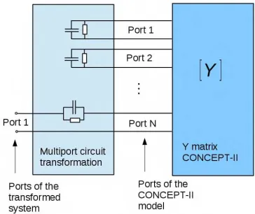
Fig. 4 shows a 16-element MRI coil, which was simulated for 208 individual port excitations. Most of these ports were equipped with resonance capacitors in post processing. Besides for feeding via one port per loop, some of the ports are connected to transformers, which are used to compensate for mutual coupling of neighboring elements. Both the antennas port responses and the electromagnetic fields can be written by matrix equations, typically based on the admittance or scattering matrix combined with corresponding so-called sensitivity matrices, which describe the linear relations of fields and port excitations. This behavior can be transformed by a linear network [11], which in this case is defined by matching and tuning capacitors as sketched in Fig. 5. In the given example, the 208 ports were reduced to 16 driving ports by a 224-port transformation network containing tuning capacitors, matching networks as well as transformer decoupling networks. The driving amplitudes and phases of the individual channels need to be optimized by means of a complex goal function. On the one hand, it is the aim to generate a homogeneous circularly polarized B1-field in the
imaging region. On the other hand, the power demands need to be lowered by reducing both, RF amplifier demands and local heating by energy absorption inside the phantom (or patient). For finding a good compromise, methods based on Eigenmode analysis were proposed [12, 13] which first define modes with respect to their power efficiency and then perform an optimization by using just the most efficient modes. Fig. 6 exemplarily shows the resulting transversal field profiles for using the best 1, 2, 4, or 7 Eigenmodes. As can be seen, at
least the first seven modes are needed to genera acceptable transmit field homogeneity. All field-map scaled to 10 µ T average, which demands 716 W net powe the seven modes. This is significantly less than a com used system-integrated body coil would need to gene similar field. Phantom experiments showed good agreem field profiles and power demands [12], thus the des simulation technique is able to predict the performan MRI arrays.
IV. BISTATICRCS COMPUTATION OFAIRCRAFT
The next example includes much more unknowns related to the previous one as many right-hand side involved. Here, a fully populated excitation matrix is req A solution is obtained by compressing the excitation m which considerably speeds up the overall solution proces
Analyzing the scattering of electromagnetic fields at targets, such as aircraft, is of fundamental importance f design and evaluation of radar systems. In common praxis, the scattering characteristics of an aircraft is exp in terms of a radar cross section (RCS). Besides materi geometry of a target, the RCS depends on frequenc incident angles associated with the illuminating field, a
as the aspect angles.Fig. 7illustrates a typical scenario
bistatic radar system: A small civil aircraft is approach airport and shall be tracked using the field of a transm antenna which is reflected by the aircraft and received at observation point. As the aircraft flies along the traj towards the airport, the RCS is varying and the scat analysis of such scenario requires the RCS evaluation
large number ofpairs of incident angles ( ', ') and
angles ( , ).
Computing such a problem with the MoM leads to a m
equation with a corresponding number of right-hand
[image:5.595.227.409.41.194.2](RHS), each representing one angle of incidence. simulation of electrically medium-size objects can be c out by fast solution algorithms, such as fast iterative [ fast direct techniques [15] based on ACA. Multiple
[image:5.595.426.594.136.249.2]Fig. 5 Transformation of a CONCEPT-II simulated structure (linear network and field sensitivities) by means of a linear general multiport circuit, here defined by lossy resonance capacitors. The ports on the right are the ports as defined in the CONCEPT-II simulation. This yields the corresponding admittance matrix as well as the 3D electromagnetic fields as a linear combination of the port voltages. After transformation these fields as well as the residual admittance matrix are described by the port excitations on the left.
problems lead to a high computational effort and require the application of sophisticated techniques for iterative solvers [16], while fast decomposition techniques are well-suited for treating multiple RHS problems [15].
For the computation of the bistatic RCS scenario shown in
Fig. 7 the Evektor EV-55 aircrafthas been considered at a typical digital audio broadcasting (DAB) frequency of 200 MHzand there was interestin computing the RCS at 1000 equidistant points on the trajectory. The work flow for this example is as follows: A surface model has been extracted from a mechanical CAD model, it has been meshed by the
external meshing toolGiD[17] and imported in CONCEPT-II.
Incident and aspect angleswere computedby a MATLAB
script, thenstored in an ASCII fileand finallyused forthe
RCS excitation. An ACA treatment of the excitation was
chosen with an accuracy of 10-5 in order to reduce the computation time of the iterative solver. For this example, two
simulations were performed, one using a fast direct solver and one simulation using a fast iterative solver. The predefined solver settings were applied in both cases.
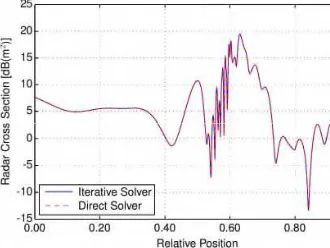
Fig. 8shows the bistatic RCS of the aircraft for different positions on the trajectory. It is indicated that the RCS values exhibit slow variations if the aircraft is in great distance from transmitter and observer because the incident and aspect angles are slowly varying. In close vicinity to transmitter and observer, these angles are rapidly changing, leading to pronounced RCS fluctuations. Computing this problem with the fast decomposition algorithm took 3.45h. Applying a fast iterative technique with a compression of the excitation required 3.76h, whereas a computation without RHS-compression would lead to a computation time of around 48h!
This example shows that arbitrary incident and aspects can be treated, making an investigation of aircraft trajec
feasible. Computing the bistatic RCS of such scenarios c carried out in an efficient way thanks to the applicatio fast direct solver and an efficient treatment of the exc matrix, respectively.
V. ANALYSIS ANDOPTIMIZATION OF AHYBRIDBROAD
REVERBERATIONCHAMBERANTENNA
Optimizing a structure with regard to specific electroma properties is an important goal in EMC and RF engine The following example shows that the MoM is a suitabl for achieving excellent antenna designs. The motivation produce an antenna for use in a reverberation chamber over a wide frequency range. Specifically, this antenna be usable in a chamber of 4.7 m × 3.0 m × 2.4 m size ov frequency range 200 MHz to 20 GHz.
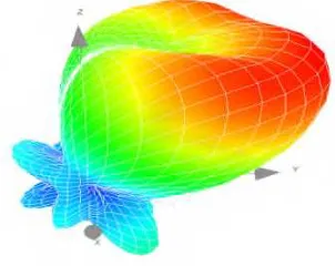
Specifically, the goal was to maximize efficiency minimizing size. Therefore the aim was to keep the reflection coefficient below 0.316 (-10 dB) over the frequency range. As the direction in which the an radiates into the RC is not important, the radiation patter not specified, but was an interesting output of the simu The solution was a dual mode antenna, whose structur hybrid of a monopole and an exponential taper like a V antenna [18]. This taper is formed from a curved metal of height 305 mm, aligned vertically over a ground pla width 300 mm and length 375 mm. Its mode of operat low frequency is like a monopole (Fig. 9) with a res frequency of approximately 250 MHz. This is determin the effective minimum length of the monopole, as defin the curved edge above the feed point. However it be more like a simple exponential taper from 400 MHz upw The key is that the taper takes over before the half-wave anti-resonance of the monopole at about 500 MHz antenna pattern is close to omnidirectional at 200 MH shows higher gain above 500 MHz: Fig. 10 shows the p at 1GHz.
[image:6.595.430.595.65.189.2]Fig. 7 Considered bistatic RCS example of the Evektor EV55 (courtesy of Evektor) associated with one observer and one transmitter for different positions on the indicated trajectory.
[image:6.595.231.411.183.271.2]For optimization of the design, the antenna was modelled with CONCEPT-II using the external toolgmshfor the meshing
[6]. The target was S11< -10 dB from 200-1000 MHz; prior
experience showed that if this were achieved, the antenna would also perform well at gigahertz frequencies.
Design parameters were varied including the length and shape of the exponential taper, the size of feed block, and also the effect of adding top-loading formed by a horizontal plate at top of the taper. The mesh size was around 10 mm at edges away from the feed, and finer (around 0.5 mm) near the feed [19]. The automated optimization process used a genetic algorithm (GA). Programs were implemented in a portable subset of GNU Octave and MATLAB, using the MATLAB GA toolbox or an in-house compatible Octave GA. The MATLAB/Octave functions also automatically wrote the CONCEPT-II input files. In the first step of the optimization process the genotype had to be decoded to get the design parameters. Agmsh(.geo) file was created with the required
parameters. Next CONCEPT-II input files were created templates and a CONCEPT-II run was started. The processing step provided the reflection coefficient |S11|.
the cost function has to be evaluated as area between |S the upper mask (see (Fig. 11).
[image:7.595.228.409.63.206.2]Validation showed good agreement between the mode measurements, both in free space and over a ground (Fig. 12).
A smooth interface between the MoM solver, MAT optimiser and thegmshmeshing program has been ach The CONCEPT-II simulations revealed a successful tran between antenna modes, and showed the initial desig already close to optimal. There were design trade-off feed-point location controls S11against power handling,
top loading controls S11against low frequency perform
[image:7.595.428.595.95.208.2]The final antenna has acceptable performance from 200 to 25 GHz, maybe higher [18]. Its frequency range c adjusted by dimensional scaling.
Fig. 9 Surface currents on a blade antenna acting like a monopole at 200MHz as simulated by CONCEPT-II. Dimensions: height 0.305m, width 0.3m, length 0.375m. Feed voltage: 1V at zero phase.
[image:7.595.429.594.274.415.2]Fig. 10 Blade antenna pattern at 1 GHz as simulated by CONCEPT-II.
Fig. 11 Cost function for the GA. Inset: parametric computer aided (CAD) forgmsh.
Fig. 12 Validation of model (S11 continues to be good up to 20 GH final fabricated antenna.
mask
[image:7.595.248.399.289.409.2]VI. COUPLING OFSTOCHASTICELECTROMAGNETICFIELDS
INTOTRANSMISSIONLINESTRUCTURES
The numerical computation of a reverberation chamber including excitation, stirrer and equipment under test (EUT) is a challenging task (Fig. 13). There are several reasons for this.
Fig. 13 a) Schematic view of a reverberation chamber with a twisted-pair cable as an EUT. b) One advantage of the presented methodology is that the chamber itself as well as the antennas and the stirrer do not have to be discretized but only the twisted pair cable.
Firstly, the chamber walls have to be included in the computation leading to huge amounts of unknowns making a numerical solution unfeasible especially in the higher frequency range. Secondly, a reverberation chamber is a completely closed cavity with a large Q factor leading to special demands both for surface-based and volume-based solvers.
In the following, a fast and efficient way to simulate the coupling of stochastic electromagnetic fields to general transmission line structures using MoM is explained. Such fields develop in reverberation chambers, where the statistical analysis is done over a range of different stirrer positions, or in overmoded cavities like aircraft fuselages or car bodies, where an ensemble of different spatial positions or nearby frequencies can be analyzed statistically. If such fields couple into transmission lines the terminal voltages or currents also become stochastic values. Analytical calculations (integral over waves) or plain numerical simulations (sum over waves) are very fast, but cannot handle general transmission line
structures. Full wave solvers such as the MoM can more arbitrary geometries of the line and the EUT itse are very slow for stochastic simulations.
To overcome this problem, CONCEPT-II includes a s technique to use stochastic fields as an excitation wi simulating the source of this field itself [21]. The techni based on a plane wave approach. A certain number of waves form one stochastic sample. Although there is n stirrer present in the simulation, but just a random n generator, the stochastic sample is calledstirrer position
consistent with its practical meaning to the simulati reverberation chambers. Many of these stirrer position generated and simulated. The main advantage is that on transmission line under test is treated conventionally, leads to a smaller number of unknowns and a computational effort.
The geometry of the reverberation chamber (includin stirrer and the antennas) or the overmoded cavity explicitly included, so no resonance problems occur and one system matrix which refers to the structure under tes
be used for all different stirrer positions. The approac also be parallelized very easily, because different indepe stirrer positions can be simulated on different CPUs.
The field strength of the stochastic field is normalized average squared magnitude of the total electric field st of = 1 V m . The simulation results are written to a text file that includes a line for each frequency and v probe. Each line, in turn, includes the results for all dif stirrer positions. Such file can be parsed very easi sophisticated mathematical software tools like MATLAB Python with NumPy and SciPy for the stochastic analys post-processing.
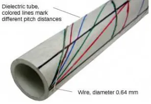
[image:8.595.228.412.108.199.2]The outlined methodology is presented using a tw double wire transmission line as an example. Such twi pair-cables are used for many applications (e.g. Ether CAN bus) to enhance the immunity against external The corresponding model of the twisted-pair as used in t is shown in Fig. 14. The line is 75 cm long and features twists, which corresponds to a pitch distance of 15 cm configuration was measured in a reverberation chamber
[image:8.595.430.595.222.331.2]Fig. 14 Open-circuited end of the practical twisted cable that was analyzed in a reverberation chamber.
[image:8.595.244.398.313.419.2]A plastic tube was used to fix the geometry of the line. This tube also determines the line spacing of 33.7 mm between the conductors.
In CONCEPT-II, each conductor is simulated by 50 straight wire segments. To include the dielectric effect of the plastic tube, a dielectric coating of the wires with an equivalent relative permittivity of 4.4 and a thickness of 1.3 mm was used. The measured and simulated number of stirrer positions is 360. In the simulation one hundred incoming waves for each stirrer position were used, which was found to be enough to get reasonable results. The measurement took about 45 min, the simulation time was approximately 3 h on a standard PC.
As an exemplary result, Fig. 15 shows the average magnitude of the coupled voltage at the beginning of the line. For an easier comparison between measurement and simulation, the coupled voltage has been normalized to the chamber constant and to half of the spacing between the conductors. For small frequencies, the protection due to the twisting is effective and the coupling to the line is very low. The coupling rises with frequency, shows the expectable transmission line resonances and reaches a maximum shortly above 700 MHz, where the wavelength equals the 2.8-fold of the pitch distance, i.e. the length of a single twist. Here, the twisting loses its protective effect. For higher frequencies and smaller wavelengths, the coupling decreases again due to radiation losses. The overall agreement between the experimental and the simulated results is very good. The simulation in CONCEPT-II is able to predict the correct amplitude, the transmission line resonances and the general frequency behavior. The superimposed noise on both curves is mainly due to the statistical uncertainty of the measurement or simulation itself that could be lowered by an even higher number of (independent) stirrer positions, but would require more effort.
VII. TRANSIENTRESPONSE OF THETOPSTRUCTURE OF THE
PEISSENBERGTOWER TOLIGHTNING
As has been mentioned earlier, the applied program package is based on integral equations that are formulated in the frequency domain. For a time-domain analysis, an inverse Fourier transform has to be carried out. Such an undertaking is particularly challenging in the case of a lightning stroke. Reasons are very low frequencies and the incorporation of the impact of the spatially distributed lightning current. Here, nonlinear effects are not considered.
The mountain called “Hoher Peissenberg” is an isolated ridge topping the surrounding terrain by about 250 m. The mountain is located in the south of Germany close to the mountains of the Alps, about 60 km far from Munich. On this mountain, the 160 m high Peissenberg Tower is located in an altitude of about 940 m above mean sea level. Fig. 16 (a) shows a picture of the tower.
Fig. 16 (a) Picture of the Peissenberg Tower, and (b) model of the Peissenberg Tower without the attached lightning channel.
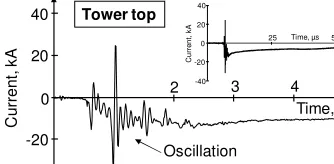
[image:9.595.426.589.38.138.2]The subject that matters here is the analysis of the frequency oscillation of the lightning currents which been measured at the top of the tower [22, 23] oscillations appeared only during the initial period o rising currents. Fig. 17 presents the current record negative lightning return stroke which occurred on Marc 1998. The inset shows that the current oscillation is res to the initial period of the current rise.
Fig. 17 Current record (tower top) of a negative return stroke which oc on March, 5th, 1998.
In the computer simulation with CONCEPT-II Peissenberg Tower according to Fig. 16 (b) is modell about 3600 triangular and rectangular ideal conducting p and about 500 wires with the conductivity of aluminum x 106S/m). The time-domain solutions are obtained fro
inverse Fourier transformation. Three different freq ranges are chosen in order to minimize the numb frequencies. Starting with a lowest frequency of 2 kH
frequency is increased in steps of f = 4 kHz up to 200 kHz. Then the frequency step is increased to f = 20 kHz in the
second frequency range up to 4 MHz. In the highest freq range between 4 MHz and 40 MHz, the frequency s
further increased to f = 80 kHz.
Fig. 18 (a) shows the numerical model for the top sect the Peissenberg Tower. The lightning strike is assum occur at one of the small Franklin rods located at the ring construction. The current measuring point was central down conductor. The return stroke process is into account by the well-known transmission-line (TL) [24]. In the frequency domain, this model uses a c
Time,
C
u
rr
e
n
t,
k
A
-20
0 2
Oscillation 20
40
3 4
Time, µs
25 5
C
u
rr
e
n
t,
k
A
-20 0
-40 20 40
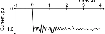
[image:9.595.428.595.261.343.2]source, where the phase velocity is given by the progress velocity of the return stroke. The inverse Fourier transformation gives a time-varying current wave starting from the point of strike and traveling along a straight wire with a constant return stroke velocity v corresponding to the chosen phase velocity (see Fig. 18b). In the simulations, the return velocity was chosen to v = 100 m/µ s. Fig. 19 shows the calculated waveform of the current at the tower top. The channel-base current is normalized to the maximum and is taken into account by a unit-step function, but with a linear rising front. The front time is chosen to 10 ns. The current at the tower top is superimposed by strong pulsation with the frequency of 12 MHz being about the same as in the current records (see Fig. 17).
Fig. 18 (a)CONCEPT-II model for the tower, and (b) simulation of the return stroke channel with the TL model.
[image:10.595.230.409.179.316.2]Oscillations in the recorded waveforms are often an indication for electromagnetic disturbance which affects the measuring system due to either electromagnetic coupling or electromagnetic radiation emitted from an external source. However, with the computer code under discussion, the oscillations could be reproduced and it is therefore very likely that the oscillations are caused by the response of the top structure of the Peissenberg Tower.
Fig. 19 With CONCEPT-II calculated current at the tower top as response of the unit-step function, but with a linear rising front. The front time is chosen to 10 ns.
VIII. CONCLUSION
In this paper it was shown that MoM can be applied to a wide range of applications. Although MoM is typically associated
with open-bounded, freely radiating problems, the exam the investigated PC chassis example clearly demonstrate the method is also a powerful tool for the analysis of c box or almost closed-cavity problems. To overcom necessity to compute the current distribution insid electrically large cavity of a reverberation chamber, a su formulation was chosen. Here, an efficient metho simulating the stochastic field coupling based on a plane approach was presented. It can be used for transmission and even for more general structures and drastically re the computational effort. For the example of a twiste cable, a good agreement between theoretical and experim results has been observed. A further strength of the M that it can easily be combined with network theory. Vi inverse Fourier transform even lightning phenomena c investigated with regard to direct and indirect e Ensuring a proper grid is essential for the quality numerical solution. Here, is has been demonstrated external tools can be applied with great success to fi optimum antenna design. Far field computations, e.g., th calculation, are the classical domain of the MoM inclusion of advanced matrix techniques provides a sign acceleration of the solution process. Of course disadvantages of the MoM should not be omitted Inherently it does not provide simple means fo investigation of non-linear problems and/or non-un material for example. In case of electrically large problem available computing power sets a practical limit for the frequencies that can be investigated, in the case of ver frequencies the electric field integral equation be numerically unstable without a low-frequency stabiliz For the classical MoM, this low-frequency limit depen the geometrical size of the structure and is somewhere range of 50 Hz to 1 kHz in many cases of practical inter any case, the user has to validate the numerically com results, this takes time and is non-optional – a statement not only true for the MoM but to any kind of num technique.
In summary it has been shown that our MoM sol ideally suited for a fast investigation of a variety of problems. The CONCEPT-II suite can be used to inves large scale problems, but it also as a sandboxing to getting insight into the electromagnetic behavior of problems and setups. Due to its open interface users ma quick answers to open questions or even new ways to their problems.
REFERENCES
[1] R.F. Harrington, “Matrix methods for field problems,” Proceed the IEEE, vol. 55, no. 2, pp. 136-149, 1967
[2] W. C. Gibson, „The Method of Moments in electromagnetics Press, Taylor Francis Group, 2015
[3] Technische Universität Hamburg-Harburg. The CONCEPT-II (2016). [Online]. Available: http://www.tet.tuhh.de/concept [4] M. Bebendorf and S. Rjasanow, “Adaptive low-rank approxim collocation matrices,” Computing, vol. 70, no. 1, pp. 1–24, Feb. 2003. [5] R. Coifman, V. Rokhlin, and S. Wandzura, “The fast multipole for the wave equation: a pedestrian prescription,” IEEE Antennas Mag., vol. 35, no. 3, pp.7–12, Jun. 1993.
[6] C. Geuzaine and J.-F. Remacle, “Gmsh: a three-dimensiona element mesh generator with built-in pre- and post-processing fac Time, µs
4 -1
1.0
2 3
0 1
0
C
u
rr
e
n
t,
p
[image:10.595.230.413.424.483.2]International Journal for Numerical Methods in Engineering 79(11), pp. 1309-1331, 2009.
[7] W. Hackbusch, „Hierarchische Matrizen: Algorithmen und Analysis,“ Berlin, Germany: Springer, 2009.
[8] W. L. Stutzman and G. A. Thiele, “Antenna Theory and Design,” Hoboken, NJ, USA: Wiley, 2013.
[9] A. Vogt, H.-D. Brüns, Q. Wu, F. Gronwald, and C. Schuster, “A measurement setup for quantification of electromagnetic interference in metallic casings,” IEEE Trans. Electrom. Compat., Dec. 2015.
[10] A. Vogt, H.-D. Brüns, and C. Schuster, “Auswirkung absorbierender Materialien auf die Verkopplung von Komponenten innerhalb eines PC Gehäuses,” Internationale Fachmesse und Kongress für Elektromagnetische Verträglichkeit, Düsseldorf, Germany, Feb. 2016.
[11] C. Findeklee, „Characterization of Transnit-Tereive Antennas for Magnetic Resonance Imaging via Moment Method and Volume Segmentation“, PH.D. Thesis TUHH, 2012, ISBN 978-3-8440-1659-8 [12] C. Findeklee, C. Leussler, P. Vernickel, U. Katscher, “RF Shimming via Efficient Modes for Massively Parallel Transmit Coils,” 23rd annual Meeting of the International Society of Magnetic Resonance Imaging (ISMRM), Toronto, 2015
[13] K. Nehrke, P. Börnert, “Eigenmode analysis of transmit coil array for tailored B1 mapping,” Magnetic Resonance in Medicine, 2010
[14] K. Zhao, M. N. Vouvakis, and J.-F Lee, "The adaptive cross approximation algorithm for accelerated method of moments computations of EMC problems," IEEE Trans. Electromagn. Compat., vol.47, no.4, pp.763-773, Nov. 2005
[15] J. Shaeffer, "Direct Solve of Electrically Large Integral Equations for Problem Sizes to 1 M Unknowns," IEEE Trans. Antennas Propag., vol.56, no.8, pp.2306-2313, Aug. 2008
[16] A. Schröder, H.-D. Brüns, C. Schuster, "A Hybrid Approach for Rapid Computation of Two-Dimensional Monostatic Radar Cross Section Problems with the Multilevel Fast Multipole Algorithm," IEEE Trans. Antennas Propag., vol.60, no.12, pp.6058-6061, Dec. 2012
[17] GiD, CIMNE, http://www.gidhome.com/ [online available] [18] A. C. Marvin, G. Esposito, J. F. Dawson, I. D. Flintoft, L. Dawson, J. K. A. Everard and G. C. R. Melia, “A wide-band hybrid antenna for use in reverberation chambers”, IEEE International Symposium on Electromagnetic Compatibility (EMC), Denver, CO, USA, pp. 222-226, 5-9 Aug. 2013, 2013.
[19] I. D. Flintoft, G. Eposito, A. C. Marvin, L. Dawson, M. P. Robinson and J. F. Dawson, “Numerical evaluation of a dual-mode antenna for use in reverberation chambers”, EMC Europe 2013, 12th International Symposium on EMC, Brugge, Belgium, 2-6 September 2013, pp. 520-525.
[20] Magdowski, M., Ladbury, J., Holloway, C., and Vick, R. (2014a), “Measurement of the stochastic electromagnetic field coupling to an unshielded twisted pair cable,” International Symp. On Electromagnetic Compatibility (EMC Europe), pages 659–664, Gothenburg, Sweden. [21] M. Magdowski, A. Schröder, H.-D. Brüns, R. Vick, „Effiziente Simulation der Einkopplung statistischer Felder in Leitungsstrukturen mit der Momentenmethode,“ Internationale Fachmesse und Kongress für Elektromagnetische Verträglichkeit, Düsseldorf, Germany, March 2014. [22] F. Fuchs, E. U. Landers, R. Schmid, and J. Wiesinger, “Lightning current and magnetic field parameters caused by lightning strikes to tall structures relating to interference of electronic systems”, IEEE Trans. Electromagn. Compat., vol. 40, no.4, pp. 444-451, 1998.
[23] F. Heidler, W. Zischank, J. Wiesinger, „Statistics of lightning current parameters and related nearby magnetic fields measured at the Peissenberg Tower,” Proc. 25th
Intern. Conf. on Lightning Protection ICLP, Rhodes, Greece, report 1.19, pp. 78 – 83, 2000
[24] M.A. Uman, R.D Brantley, Y.T. Lin, Tiller J.A., E.P. Krider, D.K. McLain, “Correlated electric and magnetic fields from lightning return strokes”, J. Geophys. Res., vol. 80, no.3, pp. 373-376, Jan. 1975.
BIOGRAPHIES
Heinz-Dietrich Brüns was bor Bremerhaven, Germany, in 1953 received the Diploma degree in elec
engineering from the Tech
Universität Braunschweig, Brun Germany, and the Ph.D. degre electrical engineering from the Univ der Bundeswehr, Hamburg, Germa 1980 and 1985, respectively. He has with the Hamburg University of Technology, Ham since1985. His research interests include the meth moments and numerical techniques in electromagnetics.
Alexander Vogt received his M.Sc Ph.D. degree in electrical engin from Hamburg University of Techn (TUHH) in 2011 and 2016, respec In 2011, he joined the research staff Institute of Electromagnetic Theo TUHH. His research interests includ and efficient simulation and mo techniques for EMI in server hou with emphasis on Boundary Element Methods (BEM) Hierarchical (H-) Matrices. Since September 2015, he i NXP Semiconductors Germany GmbH.
Christian Findeklee(Ph.D.) has a background in electrical engineerin electromagnetic theory. Today he i the Philips Research Laboratori Hamburg, Germany, working main MRI frontend hardware and technolo
Arne Schröderreceived the diploma d and the Ph.D. degree in elec engineering from the Technische Univ Hamburg-Harburg, Germany, in 200 2014, respectively. Since 2014, he is wi Institute of Applied Physics, Univers Bern, Switzerland. His research int include computational electromagnetic scattering, electromagnetic compati quasi-optics, and microwave remote sensing.
Mathias Magdowski (GSM’0 M’12) was born in Wolmir Germany in 1984. He receive Dipl.-Ing. and Dr.-Ing. degre electrical engineering from the Otto
Guericke University, Magde
Martin Robinsonis a Senior Lecturer in the Department of Electronics, University of York, UK. He received his BA and MA degrees from the University of Cambridge in 1986 and 1990, an MSc in Medical Physics from the University of Aberdeen in 1990 and a PhD in Dielectric Imaging from the University of Bristol in 1994. He worked for two years at the UK’s National Physical Laboratory and for three years at Bristol Oncology Centre, UK. He joined the University of York in 1993. His research interests include Design for EMC, Electromagnetic Measurements and the Interaction of Electromagnetic Radiation with Biological Tissues.
Fridolin H. Heidlerwas born in 1955. He received the B.Eng. and the M.Eng. degrees in electrical engineering with special emphasis on high voltage engineering from the Technical University Munich, Munich, Germany, in 1978 and 1982, respectively, and the Ph.D. and Dr.-Ing. habilitation degrees in the high-voltage engineering from the Institute of High Voltage Engineering, University of the Federal Armed Forces, Munich, in 1987 and 1999, respectively. From 1987 to 1991, he was with Industrial Engineering Company (IABG), where he was engaged in the field of electrodynamic calculations in the frequency and time domains. In 1991, he joined the Chair of High Voltage Technology and Lightning Research, University of the Federal Armed Forces Munich, where he is currently a Professor for high-voltage engineering. His current research interests include the fields of lightning research, lightning protection, and electromagnetic compatibility (EMC) with main emphasis on numerical calculations of lightning discharge process, and the measurement of the currents and electric or magnetic fields from lightning striking the Peissenberg telecommunication tower nearby Munich, Germany. He has authored or co-authored more than 150 scientific papers on lightning protection, lightning research, and electromagnetic compatibility.
Christian Schusterreceived the Diploma degree in physics from the University of Konstanz, Germany, in 1996, and the Ph. D. degree in electrical engineering from the Swiss Federal Institute of Technology (ETH), Zurich, Switzerland, in 2000. Since 2006 he is full professor and head of the Institute of Electromagnetic Theory at the Hamburg University of Technology (TUHH), Germany. Prior to that he was with the IBM T. J. Watson Research Center, Yorktown Heights, NY, where he was involved in high-speed optoelectronic package and backplane interconnect modeling and signal integrity design for new server generations. His currents interests include signal and power integrity of digital systems, multiport