Hierarchically structured metal
–
organic framework/
vertically-aligned carbon nanotubes hybrids for CO
2capture
†
Lei Ge, Li Wang, Victor Rudolph and Zhonghua Zhu*
A novel carbon/metal–organic framework composite was synthesized by confined growth of HKUST-1 in the interspace of the vertically-aligned carbon nanotube (VACNT) arrays. The grown HKUST-1 crystals are much smaller than the HKUST-1 crystals produced without the confinement growth. The derived HKUST-1/VACNT hybrids possess a hierarchical microporous–mesoporous structure. In comparison to the calculated hypothetical value assuming the physical mixture of the components, the synthesized HKUST-1/VACNT composites exhibit larger surface area and porosity, higher CO2 adsorption amount, and better CO2/N2 selectivity, which indicate the positive synergistic effect between HKUST-1 and VACNT. Besides the superior adsorption properties of hybrids, they are easier to handle than powder adsorbent for gas storage/separation.
Introduction
Metal–organic frameworks (MOFs) or porous coordination polymers (PCPs) are a new class of porous crystalline materials, which have attracted a great deal of attention over the past decade.1A lot of these fascinating crystalline hybrid materials have been synthesized and studied worldwide; their promising applications have been involved in many different areas, such as adsorption,2,3catalysis,4drug delivery,5chemical sensor6and separation membranes.7,8
Though some achievements have been made, the potential applications of MOFs have not yet been realized in industry.9 One of the main reasons to hold back the industrial application of MOFs is their stability; they tend to experience a dramatic drop in their surface area and sorption capacity when exposed to moisture. In addition, the narrow micropores of MOFs restrict the fast gas diffusion inside the pores, limiting their industrial applications in adsorption, catalysis and gas separa-tions. A key technology to realise the extensive applications of powdered materials is to develop hierarchically structured bulk materials to overcome the above problems.10By tailoring the ratio of macropores, mesopores and micropores of the bulk materials, low pressure drop and high mass transfer can be obtained simultaneously. Moreover, the bulk structure enables
the fast heat transfer and minimal mass loss during the appli-cation. Therefore, hierarchically structured bulk materials are ideal for process intensication. Some previous work has shown that MOFs with hierarchically pores can be obtained by applying longer organic spacers or surfactants; yet the process is difficult to handle, and the small change in reactants or solvents may result in nonporous or poorly crystalline structure in MOFs.11,12
The fabrication of MOFs based composites can be one promising route to achieve the hierarchical pore structure. Research on MOFs based composites has mainly focused on growing MOFs on siliceous materials or incorporating carbon materials into MOFs.13–16Yanget al.14prepared carbon nanotube (CNT)/MOF-5 hybrid composite and found that the surface area and the hydrogen storage capacity were signicantly improved compared to pure MOF-5. Xianget al.17synthesized the CNT/ [Cu3(BTC)2] hybridvia CNT incorporation. The CO2 and CH4 uptakes on this composite increased dramatically compared to the unmodied MOFs. Further improvement can be achieved by doping the CNT-modied MOFs with certain amount of Li.18 Prasanthet al.19incorporated single walled carbon nanotubes into MIL-101. The composite shows increased hydrogen adsorption with tunable pore size and pore volume. The incre-ment of CO2adsorption was also found in multi-walled CNTs/ MIL-101 composite.20Bandosz group has investigated serials of MOF and graphite oxide (GO) composites.13,21–25The enhanced pore volumes of composite was observed, which can be attrib-uted to the reaction of organic linker with the functional groups of GO. Synergistic effects on porosity and chemistry properties can lead to signicant improvements on adsorption capacity and selectivity. Silica materials were also incorporated with MOFs,
The University of Queensland, School of Chemical Engineering, Brisbane 4072, Australia. E-mail: [email protected]; Fax: +61 7 3365 4199; Tel: +61 7 33653528 †Electronic supplementary information (ESI) available: Experimental details, digital images, TGA, N2-adsoption of HKUST-1 and HKUST-1/VACNT composite,
CO2and N2adsorption isotherms of HKUST-1, high pressure CO2adsorption,
Langmuir–Freundlich isotherm t for adsorption, element analysis results of HKUST-1/VACNT composite. See DOI: 10.1039/c3ra44250k
Cite this:RSC Adv., 2013,3, 25360
Received 8th August 2013 Accepted 15th October 2013
DOI: 10.1039/c3ra44250k
www.rsc.org/advances
PAPER
Published on 16 October 2013. Downloaded by University of Queensland on 28/07/2014 03:57:04.
which displayed stable structure. The HKUST-1/MCM-41 composites showed high stability and high ammonia removal capability.15To summary, various MOFs based composites have been successfully synthesized with improved specic surface area and gas sorption capacity. However, by incorporating carbon or silica materials into MOFs, the derived composites are still in powder shape.
The conventional techniques usingne powder particles in gas adsorption and chemical reactions suffer from a number of drawbacks during operation, such as large pressure drop, poor controllability on mass transfer, low thermal conductivity, severe material loss due to carryover and lessexibility for pore network adjustment. As to thener the particles, the more the gates for the gas to come in/out, and the more difficulty for the pore network to be adjusted. In addition, it will be much harder for ne particles to realize the gas storage at low pressure. Therefore, the design of hierarchical bulk structured materials can be an effective way to solve these issues in adsorption.
In this study, the hierarchically structured MOFs/vertically-aligned carbon nanotube (VACNT) bulk composites were fabricated by connement growth of MOFs into VACNT arrays. The VACNT will enhance the dispersive interactions between MOFs and CNTs, therefore, the MOFs component will contribute to the expansion of the micropore space which favour the storage of the adsorbate. Another benet provided by VACNT is the superior thermal conductivity, which can also greatly improve the thermal conductivity of the composite for the real adsorption application. HKUST-1 is selected in this study due to its high thermal and structural stability as well as its excellent CO2adsorption performance.
Experimental details
Aligned carbon nanotube growth
The growth of carbon nanotubes was conducted by chemical vapour decomposition (CVD) of a gas mixture of catalyst source (ferrocene) and carbon source (camphor) on quartz substrate, using the pyrolysis apparatus as outlined in an earlier study.26,27 A two-stage furnace system tted with a quartz tube (inner diameter: 47 mm, length: 1.1 m) was used as the reactor. The mixture of the ferrocene (Sigma-Aldrich, 99% pure) and camphor (Sigma-Aldrich, 99.5% pure) with a camphor– ferro-cene weight ratio adjusted at 10 was put into a quartz boat and placed inside the rst part of quartz tube. The commercial quartz substrates, which had been cleaned with acetone, were located in the second part of the quartz tube at measured distances from the quartz boat. Before the CVD process, Ar gas (Coregas, 99.999%) was initiallyowed through the tube reactor to remove the residue air as the second furnace was heated up to the CVD temperature, 900C. Aer the second furnace attained the CVD temperature, the camphor–ferrocene mixture was heated up in therst furnace at a heating rate of 15C min1 until the temperature reached to155C. Argon gas was then
owed through the quartz tube at aow rate of 1.1 l min1to blow the camphor–ferrocene vapour into the second furnace. The concentration of water vapour in the gas ow was controlled by applying an argon stream passing through a water
saturator at aow rate of 5 ml min1with the corresponding water concentration in the gas ow of around 80 ppm. The thermal CVD was conducted at 900C for 30 min, and aer that, the reactor was cooled to room temperature under pure Ar atmosphere with the moist argon switched off. A deposit of carbon was found on the substrates and tube inner surfaces.
Synthesis of HKUST-1 and HKUST-1/VACNT composite
HKUST-1 and HKUST-1/VACNT composite was prepared via procedures reported in previous works.28About 1.0 g benzene-1,3,5-tricarboxylic acid (Sigma-Aldrich, 99.5% pure) was dis-solved in 30 ml of a 1 : 1 mixture of ethanol– dimethylforma-mide (DMF, analytical grade, Sigma-Aldrich). In another beaker, about 2.077 g Cu(NO3)2$3H2O (Sigma-Aldrich, 99.5% pure) were dissolved in 15 ml water. Two solutions were then mixed and stirred for 10 min before transferring into a Teon-lined stainless steel autoclave, and then the hydrothermal reactions were conducted at 100C for 7 h.
The VACNT arrays on a quartz substrate of 5 cm2.5 cm were applied for the connement growth of HKUST-1. Before the in situgrowth of HKUST-1 on VACNTs, the as-obtained VACNT arrays were treated in 30% hydrogen peroxide solution at 100C for 3 h followed by H2O wash and drying. Aer that, the VACNT forests were further treated with 30 vol.% APTES/NMP solution at 100C for 3 h. The treated VACNTs were washed with water for several time and dried in vacuum. The untreated VACNT will be specically mentioned to distinguish the treated VACNT in this work. For synthesizing HKUST-1/VACNT hybrid, the as-obtained VACNT or APTES-treated VACNT arrays were put into the auto-clave and immersed into the HKUST-1 precursor solution hori-zontally for the hydrothermal reaction. The reaction conditions were the same to the synthesis of HKUST-1 as mentioned above. Aer cooling, the resulting HKUST-1 or HKUST-1/VACNT composite on the quartz substrate were washed by DMF twice, and immersed into ethanol solvents to remove the solvated DMF. Aer that, the samples were degassed at 80C in vacuum. The HKUST-1/VACNT carpets were carefully removed from the substrate and broken into pieces for later use.
Characterization
The X-ray diffraction spectra (XRD) of HKUST-1 crystals were obtained using a Bruker Advanced X-ray Diffractometer (40 kV, 30 mA) with Cu Ka(l¼0.15406 nm) radiation at a scanning rate of 1min1from 10to 70. Attenuated total reection Fourier transform infrared spectra (ATR-FTIR) were obtained using a Nicolet 5700 ART spectrometer with an average of 64 scans in the range 400–3800 cm1. A JEOL JSM 6300 operated at 5 kV was used for scanning electron microscopy (SEM) and a JEOL 6610 coupling with an Oxford SDD energy dispersive X-ray spec-trometer (EDS) was used for elemental analysis. Transmission electron microscopy (TEM) and high-resolution transmission electron microscopy (HRTEM) were performed on a JEOL JEM-2100 microscope, with accelerating voltages of 200 kV. The samples were dispersed by sonication in ethanol, then depos-ited on a holey carbon TEM grid and dried. Thermogravimetric analysis (TGA) was carried out from 50 to 800C at 5C min1
under air using a Perkin Elmer Instruments STA 6000 Ther-mogravimetric Analyzer.
N2 physisorption isotherms of the samples were obtained using a Micromeritics TriStar II 3020 at196C, aer degassing the samples for 24 h at 150 C. The corresponding specic surface areas were calculated by the Langmuir equation at relative pressure (P/P0) between 0.005 and 0.05. Aer N2 adsorption, the samples were degassed at 150 C under a pressure of 10 mTorr until no further pressure drop was observed. The adsorption equilibrium of CO2and N2at 30C was then measured using the same instrument by immersing the sample tube in a temperature-controlled water bath. The variation in the sample temperature was minimal (<0.1 C). Desorption isotherm of the CO2or N2adsorbed in the sample was obtained by gradually decreasing the system pressure to 10 mTorr. High-pressure sorption of CO2and N2was carried out at 35C in a BEL-BG instrument with a high-accuracy magnetic suspension balance (Rubotherm). About 0.2 g of HKUST-1/ VACNT composite was degassed at 80C under vacuum for 2–4 h prior to high-pressure adsorption.
Results and discussion
Fig. 1 shows the XRD patterns of the HKUST-1 and HKUST-1/ VACNT hybrids. The structure parameters obtained by Rietveld renements are presented in Table S1 (ESI†). Based on the HKUST-1 structure data,29,30 the observed pattern and the simulated pattern show high similarity, conrming the forma-tion of pure crystalline HKUST-1. The conned growth of HKUST-1 into the interspaces of VACNT is also conrmed by the XRD pattern since the spectrum of HKUST-1/VACNT composite is similar to that of pure HKUST-1. In addition, there exists SiO2 phase in HKUST-1/VACNTs, which can be assigned to the quartz substrate of VACNTs.
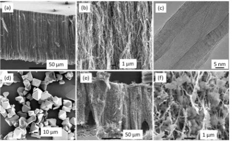
The digital images in Fig. S1 (ESI†) show the morphology of HKUST-1 particles, VACNT carpets and HKUST-1/VACNT bulk composite. Compared to the powder shape of HKUST-1, the HKUST-1/VACNT composite displays bulk shape by the connement growth of HKUST-1 in VACNT arrays. Larger scale synthesis of HKUST-1/VACNT bulk composite can be easily achieved by the scale-up of the VACNT carpet synthesis and the HKUST-1 hydrothermal growth. Fig. 2 shows the microscopy morphology of VACNT arrays, the synthesized HKUST-1 crystals and HKUST-1/VACNT hybrid. In Fig. 2a, the VACNT arrays show
high degree of vertical alignment and are well packed to form a uniform carpet-style forest with a thickness of 150 mm. High magnication image is also given in Fig. 2b, showing that most of carbon nanotubes are quite straight and parallel to each other. The interspaces between individual CNTs are less than hundreds of nanometers. The HRTEM image of typical CNTs is shown in Fig. 2c. The CNTs have an average inner-diameter of around 8 nm and each CNT consists of 15–30 layers of concentric graphene sheets with layer distance of0.34 nm. Most of the tubes are quite straight and continuously hollow, but some bamboo structures and bridged tube walls can also be observed.
The morphology of the HKUST-1 can be seen in Fig. 2d, the pristine samples display an octahedral shape with sharp edges and the original particle size is around 50 microns. Fig. 2e and f shows the CNTs become tortuous, and the HKUST-1 crystals are grown along the external surface of CNTs,lling up the gaps between CNTs aer the conned growth of HKUST-1 into VACNT carpet. The morphology of HKUST-1 is also altered signicantly by growing in the conned interspace of VACNT. It is noteworthy that the crystal size of HKUST-1 in the con ne-ment growth is much smaller (sub-micron) than that of the free grown HKUST-1 (Fig. 2d). Similarndings have been reported that nano-sized HKUST-1 crystals have been synthesized in the connement growth of HKUST-1 inside anodic aluminum oxide.31 Closer examination of the cross-section of HKUST-1/ VACNT composite reveals that higher density of HKUST-1 is found on the exposed side of VACNT, while lower crystals density on the substrate side. The difference in the crystal growth density might be attributed to the diffusion resistance of HKUST-1 precursor in VACNT arrays. Different morphology was observed in HKUST-1/VACNT composite if untreated VACNTs were applied for HKUST-1 conned growth (Fig. S2, ESI†). Severe space occlusion was seen, and the large HKUST-1 parti-cles can only be observed on the tips of VACNT arrays. While in the interspaces of VACNTs, there hardly exist HKUST-1 crystals. Compared to the better dispersion of HKUST-1 inside the treated VACNT arrays, it can be concluded that the pre-treat-ment of the VACNTs can facilitate the HKUST-1 growth; the surface functional groups on CNTs can act as nucleation sites and form MOFs by heterogeneous nucleation.32–34
Fig. 1 (a) XRD spectra of the HKUST-1 (black dots: observed, red line: simulated) and HKUST-1/VACNTs; (b) the structure diagram of HKUST-1 (red: O, blue: Cu, black: C, green: H).
Fig. 2 SEM and TEM morphologies of as-synthesized VACNTs (a–c), HKUST-1 (d) and HKUST-1/VACNT hybrid (e and f).
[image:3.595.311.548.50.196.2] [image:3.595.47.289.595.689.2]The thermal stability of derived HKUST-1, VACNTs and HKUST-1/VACNT hybrid were investigated by TGA, as shown in Fig. S3 (ESI†). The initial temperature of weight loss in VACNT was observed until 550 C, indicating the high graphitic degree of the as-synthesized VACNT arrays. The oxidation ends above 650C and the burnt residue can be assigned to the iron oxide catalyst residue in the VACNTs. As to HKUST-1, a steady weight loss up to the temperature of 320C is resulted from the removal of intra crystalline DMF. The steady weight loss indi-cates a slow release of DMF. Compared to HKUST-1, the solvent removal in HKUST-1/VACNT hybridnishes at lower tempera-ture (300 C). The easy solvent removal in hybrid can be attributed to the connement growth of small HKUST-1 parti-cles and the formation of effective solvent diffusion paths in the hierarchical porous structure.
The dramatic weight loss in HKUST-1 and HKUST-1/VACNT at beyond 350C is due to the decomposition of trimesic acid linkers, leaving CuO as thenal product.28For the HKUST-1/ VACNT composite, the decomposition of trimesic acid linkers above 350 C leads to the release of oxygen atom and the exposure of Cu metal, which may involve the catalytic oxidation of VACNTs and destroy their graphitic structure. In this case, the decomposition of VACNTs started at lower temperature and completed before reaching 650C. The residues are the mixture of copper oxide and iron oxide from HKUST-1 and VACNTs, respectively. For the evaluation of the HKUST-1 contents in the composite, the weight loss from linker decomposition in HKUST-1 and HKUST-1/VACNT was calculated. The initial decomposition temperature (Ti) was 305 and 290C for HKUST-1 and HKUST-HKUST-1/VACNT composite, respectively. The residue weight reached to a steady platform at350C, which is the terminal decomposition temperature. Since the VACNTs are stable at this temperature range (290/305C to 350C), the ratio of the weight loss percentage between HKUST-1/VACNT and HKUST-1 reects the HKUST-1 content in the composite. The weight ratio of HKUST-1 (q) in the HKUST-1/VACNT composite is calculated as:
q¼mi-compositemt-composite=mi-composite mi-HKUSTmt-HKUST=mi-HKUST
100% (1)
where mi-HKUST and mi-composite are the sample weights of HKUST-1 and HKUST-1/VACNT composite at the initial decomposition temperature, mt-HKUST and mt-composite are the sample weights of HKUST-1 and HKUST-1/VACNT composite at the terminal decomposition temperature, respectively. The HKUST-1 content in composite is therefore calculated to be around 43 wt%. To further conrm the HKUST-1 content, the elemental analysis on HKUST-1/VACNT composite was con-ducted by EDS (Fig. S4 and Table S2, ESI†). Based on the mole ratio of copper and carbon, the HKUST-1 content in the HKUST-1/VACNT composite was calculated as 46.5 wt%, similar to the result derived from weight loss. In addition, the HKUST-1 loading percentage can be affected by the areal density and height of VACNTs which are uctuated during the CVD growth. In this study, the variation of HKUST-1 loading content on different batches of VACNTs was less than 10%.
Nitrogen sorption experiments were performed on HKUST-1, as-synthesized VACNTs and HKUST-1/VACNT composite. The isotherms and cumulative pore volume results were shown in Fig. S5 (ESI†). The multipoint BET surface area and pore volume were calculated and listed in Table 1. In order to compare the properties of synthesized HKUST-1/VACNT composite, the hypothetical values were also calculated based on mixing the HKUST-1 and VACNT at same weight ratio as in the synthesized HKUST-1/VACNT composite. HKUST-1 exhibits high amount of nitrogen sorption at low pressure and its isotherm is type I, typical for microporous materials. The hysteresis indicates the delayed desorption potentially caused by the hindrance in N2 removal due to the presence of solvent residue molecules. The BET surface area of the derived HKUST-1 is 1382.6 m2g1, in line with previous reported values (1270 m2g1 (ref. 35) and 1333 m2g1(ref. 36)). VACNT arrays exhibit a type IV isotherm based on IUPAC classication,37 suggesting the existence of mesopores in the samples. Its BET surface area is 53.9 m2g1, including the outer and the interspaced surface area of the arrays, as well as a few of interior sites of open-ended CNTs.
HKUST-1/VACNT composite exhibits a Type II isotherm, indicating the presence of both mesopores and micropores. The composite shows a signicantly higher BET surface area (726.7 m2g1) than pure VACNTs (53.9 m2g1). The excess N2 adsorption is attributed to both surface area and pore volume raise from inter-grown HKUST-1. For comparison, the VACNT was physically mixed with same content of HKUST-1 (43%), and the N2-adsorption isotherm of the mixture is shown in the Fig. S6 (ESI†). The surface area of the physical-mixed HKUST-1-VACNTs is measured to be consistent with the calculated hypothetical value shown in Table 1. Moreover, its surface area was signicantly lower (630.3 m2g1) that that of the synthe-sized HKUST-1/VACNT hybrid. For pore volume, it is obvious that the synthesized HKUST-1/VACNT composite exhibits much higher porosity than the hypothetical physical mixture of VACNT and HKUST-1, especially in the mesopore range. The enhanced surface area and porosity from the connement growth of HKUST-1 inside VACNT arrays indicates that syner-gistic interaction between HKUST-1 and VACNT. The functional groups on CNTs provide heterogeneous nucleation sites for the growth of small HKUST-1 crystals along the CNTs, resulting in the mesoporous and microporous volume increment of the
nal HKUST-1/VACNT hybrid.
As shown in Fig. S5b (ESI†), VACNTs present almost no cumulative pore volume in the micropore range, since the diameter of CNTs is in the mesopore range and most of tubes are close-ended. On the contrary, HKUST-1 is dominated by micropores; the dramatic cumulative pore volume increment occurs mainly in micropore range while negligible in meso-porous range. The small mesomeso-porous volume can be assigned to the aggregation pores. Compared to pure HKUST-1, the total micropore volume of HKUST-1/VACNT composite reduces due to the component of low-microporous VACNT (Table 1). It is also noteworthy that a sharp increase of accumulated pore volume exists in the micropore range, owing to the additional micropores formed between HKUST-1 and CNTs. Also the mesoporous volume of synthesized composite is three times
higher than that of hypothetical mixture. The signicant mes-opore volume increase indicates the formation of hierarchical porous morphology by the in situ growth of HKUST-1 into VACNT arrays. Different types of functional groups on VACNT will lead to HKUST-1 grown with relatively disordered structure. The increment of the porosity can be assigned to this disor-dered arrangement in composite structure.13
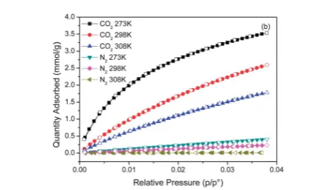
As reported in the previous reference, HKUST-1 demon-strated the potential of CO2/N2separation in the post- and pre-combustion capture technologies.36 In this study, the adsorp-tion capacities of pure CO2 and N2 for HKUST-1/VACNT composite were evaluated and shown in Fig. 3, in comparison to HKUST-1 and physical mixture of the HKUST-1/VACNT (Fig. S7, ESI†). All gas adsorption is completely reversible. The CO2 uptake on both samples shows a gradual increase with pressure, and the increment slope of CO2is much higher than that of N2, indicating a disproportionately high affinity and adsorption capacity for CO2on both samples. The high adsorption capacity of CO2is mostly attributed to the specic interactions between quadrupolar CO2molecules and partial positive charges on the coordinatively unsaturated metal sites in HKUST-1.38 At 0 C and 132 kPa, the CO2 adsorption capacities on HKUST-1, the HKUST-1/VACNT composite and the physical mixture of VACNTs and HKUST-1 are 9.5, 3.5 and 3.1 mmol g1, respec-tively. The adsorption capacities of pure CO2on the HKUST-1/ VACNT composite are higher than that on the physical mixture of VACNTs and HKUST-1, which can be assigned to the syner-gistic effect between HKUST-1 and VACNTviathe connement growth of HKUST-1. On the other hand, the adsorption capacity is exothermic as shown by the decrease of the equilibrium capacity at higher temperature. The CO2adsorption value on
the physical mixture of HKUST-1 and VACNTs is also calculated and compared with the measured high-pressure CO2 adsorp-tion value on HKUST-1/VACNT composite (Fig. S8, ESI†). The higher CO2adsorption of the composite over the hypothetical mixture value shows the synergistic effect between HKUST-1 and VACNT, probably derived from the increase in the hypo-thetical surface area and porosity (Table 1). Also the enhance-ment of sorption capacity can be attributed to the reducing of HKUST-1 crystal size.39
The measured CO2and N2sorption data can be welltted by the Langmuir–Freundlich model (Fig. S9, ESI†), with the derived parameters shown in Table S3 (ESI†). The calculated saturation capacities of CO2and N2on the HKUST-1 are 14.12 and 4.62 mmol g1, respectively. On contrary, the HKUST-1/ VACNT hybrid can absorb 7.83 and 2.04 mmol g1of CO
2and N2at saturation. Considering the weight percentage of HKUST-1 in the composite, the normalized CO2adsorption capacity per gram of HKUST-1 in the hybrid can reach to a value signicantly larger than that of the pure HKUST-1, 17.65 mmol gHKUST-11, while the normalized N2 adsorption capacity (4.6 mmol gHKUST-11) is similar to that of the HKUST-1. Therefore, the improvement on CO2/N2adsorption selectivity can be expected in the composite, as shown in Fig. 4. The selectivity shows a descending trend with the operation pressure. In the whole pressure range, the gas adsorption is more selective on HKUST-1/VACNT hybrid than that on pure HKUST-1, which can be attributed to the cooperative interaction between HKUST-1 and VACNTs.
[image:5.595.40.562.64.139.2]The curvature of planar graphene layers into cylinders in CNTs induces the electron transfer from the concave inner
Table 1 Parameters of the porous structures of HKUST-1, VACNT and HKUST-1/VACNT composite
BET surface area (m2g1)
Total volume (cm3g1)
Mesopore volume (cm3g1)
Micropore volume (cm3g1)
VACNT 53.9 0.066 0.041 0.025
HKUST-1 1382.6 0.649 0.078 0.571
HKUST-1/VACNT composite 726.7 0.466 0.174 0.292 HKUST-1/VACNT mixturea 625.2 0.317 0.057 0.260
aHypothetical values derived assuming the physical mixture of the VACNT and HKUST-1.
Fig. 3 CO2 and N2 adsorption isotherms of HKUST-1/VACNT composite at
different temperatures.
Fig. 4 The CO2/N2 adsorption selectivity on HKUST-1 and HKUST-1/VACNT
composite.
[image:5.595.306.554.556.702.2] [image:5.595.45.289.564.702.2]surface to the convex outer surface of CNTs, leading to higher electron density on the CNT external surface than inside CNT channels. In this case, by growing HKUST-1 on the CNT external surface, the electrostatic interactions of CO2 adsorption may be enhanced. The strength of electrostatic interactions can inuence the gas separation especially for the gas components with different dipoles/quadrupoles.40 Therefore, the enhanced CO2/N2selectivity can be observed as in Fig. 4.
To better understand the adsorption difference between HKUST-1 and HKUST-1/VACNT hybrid, the Clausius–Clapeyron equation (eqn (2)) was used to calculate the isosteric heats of adsorption,DHads, from the slope of the best-t line for lnp
versusT1at each loading.
ðlnpÞq¼ DHads
R
1 T
þC (2)
here,qis the amount of adsorbed gas (mmol g1) at 273 K, 298 K and 308 K, p is the exact pressure (bar), T is the absolute temperature (K),Ris the ideal gas constant (J mol1K1).
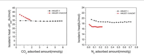
As shown in Fig. 5, the isosteric heat of CO2adsorption on HKUST-1 maintains at around 29 kJ mol1, which is in line with the reported values for HKUST-1 framework (29.8 kJ mol (ref. 41) and 28.0 kJ mol1 (ref. 18)). In contrast, the isosteric heat of CO2 adsorption on HKUST-1/VACNT hybrids shows a descending trend with increasing CO2adsorption amount; the calculated heat for the composite is 37.0 kJ mol1 at low adsorption amount, much higher than that for HKUST-1. This trend matches well with the ndings in HKUST-1/AAO composite.31Therefore, it is clear that the hierarchical struc-ture of HKUST-1/VACNT hybrid can facilitate the CO2storage at low pressure. On the other hand, the isosteric heat of N2 adsorption on HKUST-1/VACNT hybrid displays similar trends as that of HKUST-1, yet with the lower values. The variation of adsorption heat on CO2 and N2 with different dipoles/quad-rupoles can be attributed to the change of electrostatic inter-action by CNTs. It can be seen that by the conned growth of HKUST-1 in VACNT arrays, stronger affinity of CO2but weaker affinity of N2 molecules is resulted for the composite, thus enhancing the adsorption selectivity (Fig. 4). However, lower gas saturation capacity for HKUST-1/VACNT is observed than HKUST-1. One feasible way to further enhance the saturation capacity of HKUST-1/VACNT hybrid is to increase the HKUST-1 content in the composite via the modication of synthesis conditions.
Conclusions
In summary, the novel carbon/MOF composite material has been synthesized by growing HKUST-1 into the interspace of the VACNT arrays. The interspaces of VACNT arrays provide the space for the conned growth and result in the derived sub-micron HKUST-1 crystals. Compared to pure VACNT, the mes-opore and micrmes-opore volumes of HKUST-1/VACNT hybrid are signicantly improved. The CO2and N2adsorption was evalu-ated on this HKUST-1/VACNT composite. The saturation capacities of CO2on HKUST-1/VACNT hybrid can reach to 7.83 mmol g1 at 298 K. Compared to HKUST-1, the adsorption selectivity of CO2 over N2 on HKUST-1/VACNT hybrids is enhanced in all the pressure range, owing to the synergistic effect between HKUST-1 and VACNTs. The HKUST-1/VACNT hybrids show some promising prospects, including the high adsorption capacity, the tunable porosity, and the bulk shape. Further work can be conducted on thicker VACNT arrays to synthesize larger MOF/VACNT bulk composites. The areal density of VACNTs can also be adjusted by CVD synthesis and post-functionalisations for the controllable MOFs growth. The approach developed in the study could also propose a way for the use of VACNTs to develop hierarchically porous structured materials for the applications that require favourable mass transport, such as catalysis, gas separation, energy storage and conversion.
Acknowledgements
The nancial support by Australian Research Council (ARC) discovery project is greatly appreciated. The authors acknowl-edge the facilities, and the scientic and technical assistance, of the Australian Microscopy & Microanalysis Research Facility at the Centre for Microscopy and Microanalysis, The University of Queensland.
Notes and references
1 H. Li, M. Eddaoudi, M. O'Keeffe and O. M. Yaghi,Nature, 1999,402, 276–279.
2 Z. Ni, J. P. Jerrell, K. R. Cadwallader and R. I. Masel,Anal. Chem., 2007,79, 1290–1293.
3 Z. R. Herm, J. A. Swisher, B. Smit, R. Krishna and J. R. Long, J. Am. Chem. Soc., 2011,133, 5664–5667.
4 J. Lee, O. K. Farha, J. Roberts, K. A. Scheidt, S. T. Nguyen and J. T. Hupp,Chem. Soc. Rev., 2009,38, 1450–1459.
5 P. Horcajada, C. Serre, G. Maurin, N. A. Ramsahye, F. Balas, M. Vallet-Regi, M. Sebban, F. Taulelle and G. Ferey,J. Am. Chem. Soc., 2008,130, 6774–6780.
6 G. Lu and J. T. Hupp, J. Am. Chem. Soc., 2010,132, 7832– 7833.
7 H. Bux, F. Liang, Y. Li, J. Cravillon, M. Wiebcke and J. Caro, J. Am. Chem. Soc., 2009,131, 16000–16001.
8 H. Guo, G. Zhu, I. J. Hewitt and S. Qiu,J. Am. Chem. Soc., 2009,131, 1646–1647.
9 A. U. Czaja, N. Trukhan and U. Muller,Chem. Soc. Rev., 2009,
38, 1284–1293.
Fig. 5 The isosteric heats of adsorption (DHads) on the HKUST-1 and HKUST-1/
VACNT composite.
[image:6.595.45.286.610.702.2]10 F. Rezaei, A. Mosca, P. Webley, J. Hedlund and P. Xiao,Ind. Eng. Chem. Res., 2010,49, 4832–4841.
11 X. S. Wang, S. Ma, D. Sun, S. Parkin and H. C. Zhou,J. Am. Chem. Soc., 2006,128, 16474–16475.
12 L. G. Qiu, T. Xu, Z.-Q. Li, W. Wang, Y. Wu, X. Jiang, X. Y. Tian and L.-D. Zhang,Angew. Chem., Int. Ed., 2008,47, 9487–9491. 13 C. Petit, J. Burress and T. J. Bandosz,Carbon, 2011,49, 563–
572.
14 S. J. Yang, J. Y. Choi, H. K. Chae, J. H. Cho, K. S. Nahm and C. R. Park,Chem. Mater., 2009,21, 1893–1897.
15 A. M. B. Furtado, J. Liu, Y. Wang and M. D. LeVan,J. Mater. Chem., 2011,21, 6698–6706.
16 J. Gorka, P. F. Fulvio, S. Pikus and M. Jaroniec, Chem. Commun., 2010,46, 6798–6800.
17 Z. Xiang, X. Peng, X. Cheng, X. Li and D. Cao,J. Phys. Chem. C, 2011,115, 19864–19871.
18 Z. Xiang, Z. Hu, D. Cao, W. Yang, J. Lu, B. Han and W. Wang, Angew. Chem., Int. Ed., 2011,50, 491–494.
19 K. P. Prasanth, P. Rallapalli, M. C. Raj, H. C. Bajaj and R. V. Jasra,Int. J. Hydrogen Energy, 2011,36, 7594–7601. 20 M. Anbia and V. Hoseini,Chem. Eng. J., 2012,191, 326–330. 21 C. Petit and T. J. Bandosz,Adv. Mater., 2009,21, 4753–4757. 22 C. Petit and T. J. Bandosz,Adv. Funct. Mater., 2010,20, 111–118. 23 C. Petit, L. Huang, J. Jagiello, J. Kenvin, K. E. Gubbins and
T. J. Bandosz,Langmuir, 2011,27, 13043–13051.
24 C. Petit, B. Mendoza and T. J. Bandosz, ChemPhysChem, 2010,11, 3678–3684.
25 B. Levasseur, C. Petit and T. J. Bandosz,ACS Appl. Mater. Interfaces, 2010,2, 3606–3613.
26 M. Kumar and Y. Ando,Chem. Phys. Lett., 2003, 374, 521– 526.
27 L. Ge, L. Wang, A. Du, M. Hou, V. Rudolph and Z. Zhu,RSC Adv., 2012,2, 5329–5336.
28 J. Liu, J. T. Culp, S. Natesakhawat, B. C. Bockrath, B. Zande, S. G. Sankar, G. Garberoglio and J. K. Johnson,J. Phys. Chem. C, 2007,111, 9305–9313.
29 S. S.-Y. Chui, S. M.-F. Lo, J. P. H. Charmant, A. G. Orpen and I. D. Williams,Science, 1999,283, 1148–1150.
30 M. Hartmann, S. Kunz, D. Himsl, O. Tangermann, S. Ernst and A. Wagener,Langmuir, 2008,24, 8634–8642.
31 M. Maksoud, N. Roques, S. Brandes, L. Arurault and J.-P. Sutter,J. Mater. Chem. A, 2013,1, 3688–3693.
32 S. Hermes, F. Schr¨oder, R. Chelmowski, C. W¨oll and R. A. Fischer,J. Am. Chem. Soc., 2005,127, 13744–13745. 33 M. Shoaee, M. W. Anderson and M. P. Atteld,Angew. Chem.,
Int. Ed., 2008,47, 8525–8528.
34 C. Scherb, A. Sch¨odel and T. Bein,Angew. Chem., Int. Ed., 2008,47, 5777–5779.
35 J. Moellmer, A. Moeller, F. Dreisbach, R. Glaeser and R. Staudt,Microporous Mesoporous Mater., 2011, 138, 140– 148.
36 Q. Min Wang, D. Shen, M. Bulow, M. Ling Lau, S. Deng, F. R. Fitch, N. O. Lemcoff and J. Semanscin, Microporous Mesoporous Mater., 2002,55, 217–230.
37 R. Pierotti and J. Rouquerol,Pure Appl. Chem., 1985,57, 603– 619.
38 K. Sumida, D. L. Rogow, J. A. Mason, T. M. McDonald, E. D. Bloch, Z. R. Herm, T.-H. Bae and J. R. Long, Chem. Rev., 2012,112, 724–781.
39 L. Ge, W. Zhou, V. Rudolph and Z. Zhu,J. Mater. Chem. A, 2013,1, 6350–6358.
40 J.-R. Li, Y. Ma, M. C. McCarthy, J. Sculley, J. Yu, H.-K. Jeong, P. B. Balbuena and H.-C. Zhou,Coord. Chem. Rev., 2011,255, 1791–1823.
41 C. R. Wade and M. Dinca, Dalton Trans., 2012, 41, 7931– 7938.