ANALYSIS OF THE INTERFACE FORMED BY
PREMACHINED COBALT CHROMIUM IMPLANT
ABUTMENT BASE WITH CAST ON COBALT
CHROMIUM ALLOY BEFORE AND AFTER SIMULATED
PORCELAIN FIRING – AN IN VITRO STUDY
Dissertation Submitted to
THE TAMILNADU Dr. M.G.R. MEDICAL UNIVERSITY
In partial fulfilment for the Degree of
MASTER OF DENTAL SURGERY
BRANCH I
PROSTHODONTICS AND CROWN & BRIDGE
THE TAMILNADU Dr. M.G.R MEDICAL UNIVERSITY
CHENNAI
DECLARA TION BY THE CANDIDATE
I hereby declare that this dissertation titled
"ANALYSIS OF
THE INTERFACE FORMED BY PREMACHINED COBALT
CHROMIUM IMPLANT ABUTMENT BASE WITH CAST
ON COBALT CHROMIUM ALLOY BEFORE AND AFTER
SIMULA TED PORCELAIN FIRING -AN
IN VITRO
STUDY"
is a bonafide and genuine research work carried out by me under the
guidance of
Dr. HARIHARAN RAMASUBRAMANIAN,
M.D.S.,
Reader, Department of Prosthodontics and Crown & Bridge, Ragas Dental College and Hospital, Chennai.Place: Chennai
(Y'
Dr. R. SETHU RAMAN,
Post Graduate Student,
Department of Prosthodontics and
Crown & Bridge,
•
•
CERTIFICATE
This is t.o certify that the dissertation titled ''ANALYSIS OF
THE INTERFACE FORMED BY PREMACHINED
COBALT
CHROMIUM IMPLANT A
.
BUTMENT BASE WITH CAST ON
COBALT CHR.OMIUM ALLOY
.
BEFORE AND AFTER SIMULATED
PORCELAIN F'IRING - AN
IN VITRO
STUDY'' is a bonafide record work
done by Dr. R. SETHU RAMAN unde·r our guidance and to our satisfaction.
during his post graduate study p
.
eriod b
·
etween 2015 - 2018.
This dissertation is submitted to THE TAMILNADU Dr. M.G"R.
MEDICAL UNIVERSITY, in partial fulfillment for the Degree of MASTER
OF DENT AL SURGERY - PROSTHODONTICS AND CROWN &
BRIDG
·
E, BRANCH I. It has not been submitted. (partial or full) for the award
of any other degree or diploma.
Guided by:
-
-r. N.S. Azhagarasan, M.D.S.,
Dr .. Hariharan Ramasubramani.an,M.D.,S.,
Principal, Professor and Head of the Reader,
Department,
Department of Prosthodonics and Crown &
Department of Prosthodontics and
Bridge,
Crown
.&
Bridge,
Ragas Dental College & Hospital,
Ragas Dental College & Hospital,
Chennai.
PRINCIPAL
RAGAS DENTAL COLLEGE AND f10SPITAL
UTHAND,I.
CHENNAl-600 119.
,,
•
Chennai.
READER
DEPT�OF
f
J
·
ROSTHODONTICS
AND Cl�O
\
.
VN & l3RIDGE
Ra
ga
s
Dental
ColJege
&
Hospital
THE TAMILNADU Dr. M.G.R. MEDICAL UNIVERSITY
CHENNAI
PLAGIARISM CERTIFICATE
This is to certify the dissertation titled
"ANALYSIS OF THE
INTERFACE FORMED BY PREMACHINED COBALT
CHROMIUM IMPLANT ABUTMENT BASE WITH CAST
ON COBALT CHROMIUM ALLOY BEFORE AND AFTER
SIMULATED PORCELAIN FIRING -
AN
IN VITRO
STUDY"
of the candidateDr. R. SETHU RAMAN
for the award of· Degree of MASTER OF DENTAL SURGERY in BRANCH I
-PROSTHODONTICS AND CROWN & BRIDGE.
On verification with the urkund.com website for the purpose of
plagiarism check, the uploaded thesis file contains from introduction to
conclusion pages shows 9% percentage of plagiarism, as per the report
generated and it is enclosed in Annexure - V.
Date: -� { {).. { .;i._o\ cf
Post Graduate Student,
Department of Prosthodontics and Crown & Bridge,
Ragas Dental College & Hospital, Chennai.
Place: Chennai.
Dr. HARIHARAN RAMASUBRAMANIAN, M.D.S.,
Guide, Reader,
Department of Prosthodontics and Crown & Bridge, Ragas Dental College & Hospital,
Chennai.
ACKNOWLEDGEMENT
With all the writings done, this note of thanks is the final piece to my dissertation. The whole period of this work from the beginning to the end was a tedious one that made me meet many new people and also increased the bond with those whom I already know. All of them have helped me learn so many aspects not only in the field of dentistry but also in my personal development. Finishing this thesis was difficult but by the end I feel satisfied and content with all the experience that I have gained and they will surely have an everlasting impact throughout the journey in my career.
First of all, I thank, Dr. N.S. Azhagarasan M.D.S, Principal, Professor
& Head, Department of prosthodontics & Crown and Bridge for providing the
opportunity to take up this thesis topic. His continuous support, conscientious encouragement helped me in improving my work. I am grateful to him for letting me use the amenities of the department that enabled to finish my thesis work on time.
I would like to express my heartfelt gratefulness to my guide, Dr.
Hariharan Ramasubramanian, M.D.S., Reader, for his guidance and support,
I thank, Dr. K. Chitra Shankar M.D.S, Professor, who is a great source of inspiration and a tremendous mentor. A strict and most disciplined person by profession who has helped me understand my profession better. Her constructive critics have always helped me improve both as a professional and more importantly as a person.
I thank Dr. S. Jayakrishnakumar, M.D.S., Professor, for his inspiration, motivation, encouragement and personal attention. His friendly nature and his calm composure have always helped me in approaching him for seeking clarifications during my entire course.
I would also like to thank Dr. M. Saravana Kumar, M.D.S., Professor, who has provided me with great support in doing clinical cases in a correct and orderly manner. He has been a role model of perfection to me in each and every aspect during these three years of academic and clinical progress.
I would also like to thank Dr. Vallabh Mahadevan, M.D.S. Reader, Dr.
Hariharan R, M.D.S. Reader, Dr. Vidhya, M.D.S. Reader, Dr. Kamakshi,
M.D.S., Dr. Shameem, M.D.S., Dr. Mahadevan, M.D.S., Dr. Manoj Kumar,
M.D.S. for their valuable suggestions and help given throughout my study.
I take this opportunity to sincerely acknowledge University of Madras, Chennai for obtaining SEM pictures in time and I would like to thank Mr. Ajay
PhD Student, Chennai, for helping me with SEM analysis. I would like to thank
Mr. Venkat Ramana and Mr. Avdesh, Excel water jet for helping me in
I thank Mr. T. R. Parthasarathy, from Met Mech Engineers, who greatly helped me to understand the metallurgical analysis and hardness measurements done in my study.
I would like to thank my statistician Mr. Thirunavukarasu M.J,
Assistant Professor, for his valuable support in the statistical work.
I am extremely thankful to my colleague Dr. Ashwini Sukanya GU., for all the support she provided during the thesis without whom my work could not have been completed on time.
I thank my friends, Dr. Swathy S, Dr. Priya Dharshini, Dr. Gayathree
Alagirisamy, Dr. Janani Dakshinamurthy, Dr. Abinaya Sekar, Dr. Arul
Kumar, Dr. Pavan Kumar V, Dr. Revathi D, Dr. Sherin Grace babu, Dr.
Konda Chaturya Anand, Dr. Mahalakshmi, Dr. Varun, Dr. Bhanu Chander,
Dr. Syed, Dr. Ambedkar, Dr. Rakshagan, Dr. Aswana, Dr. Arjun Badimela,
Dr. Jensy Sara George, Dr. Maniamudhu, Dr. Sameen, Dr. Asish Martin, Dr.
Manimala, Dr. Aishwarya K, Dr. Surabhi Halder, Dr. Yasmin Fathima, who
all have helped me a lot throughout my post graduate course. They were my emotional backbone who have given me amazing experiences and memories that I will cherish throughout my life.
CONTENTS
S.NO.
TITLE
PAGE
NO.
1. INTRODUCTION 1
2. REVIEW OF LITERATURE 6
3. MATERIALS AND METHODS 20
4. RESULTS 40
5. DISCUSSION 62
6. CONCLUSION 71
7. SUMMARY 74
LIST OF TABLES
TABLE NO.
TITLE PAGE
NO.
I Elemental Composition of as received premachined implant abutment base by EDS analysis
42 II Elemental Composition of as received casting alloy
by EDS analysis.
42 III Elemental composition at Point A (9µm from
interface towards the premachined base) by EDS analysis of Group I samples.
43
IV Elemental composition at Point B (4.5µm from interface towards the premachined base) by EDS analysis of Group I samples.
44
V Elemental composition at Point C (at the interface) by EDS analysis of Group I samples.
45 VI Elemental composition at Point D (4.5µm from
interface towards the cast alloy)by EDS analysis of Group I samples.
46
VII Elemental composition at Point E (9µm from interface towards the cast alloy) by EDS analysis of Group I samples.
VIII Elemental composition at Point A (9µm from interface towards the premachined base) by EDS analysis of Group II samples.
48
IX Elemental composition at Point B (4.5µm from interface towards the premachined base) by EDS analysis of Group II samples.
49
X Elemental composition at Point C (at the interface) by EDS analysis of Group II samples.
50 XI Elemental composition at Point D (4.5µm from
interface towards the cast alloy) by EDS analysis of Group II samples.
51
XII Elemental composition at Point E (9µm from interface towards the cast alloy) by EDS analysis of Group II samples.
52
XIII Basic Values of Vickers Hardness for Group I test samples
53 XIV Mean hardness values of Group I test samples. 55
XV Basic Values of Vickers Hardness for Group II test samples
XVII Comparative evaluation between mean hardness values at implant abutment base, interface and cast alloy of Group I samples using one-way ANOVA test.
59
XVIII Comparative evaluation between mean hardness 59
XIX 60
XX 60
XXI
values at implant abutment base, interface and cast alloy of Group I samples using Post Hoc tukey
HSD test
Comparative evaluation between mean hardness values at implant abutment base, interface and cast alloy of Group II samples using one-way ANOVA test.
Comparative evaluation between mean hardness values at implant abutment base, interface and cast alloy of Group II samples using Post Hoc tukey HSD test.
Comparative evaluation of mean hardness values at implant abutment base, interface and cast alloy between as cast samples (Group I) and samples subjected simulated porcelain firing (Group II).
ANNEXURE I
METHODOLOGY – OVERVIEW
ANNEXURE II
FIGURES
Fig. No. TITLE
Fig.1: Polyvinylsiloxane impression material 1a. Putty consistency, regular set 1b. Light body consistency, regular set
Fig.2: Bard Parker blade No.15
Fig.3: Laboratory implant replica
Fig.4: Clear auto polymerizing acrylic resin
Fig.5: Screw retained engaging cast on abutment with premachined Co-Cr base
Fig.6: Inlay casting wax
Fig.7: Modelling wax
Fig.8: Auto polymerizing resin
Fig.9: Wax sprue wire 2.5mm
Fig.10: Surfactant
Fig.11: Graphite free phosphate bonded investment
Fig.13: Distilled water
Fig.14: 0.8mm beading wire
Fig.15: Nickel and Beryllium free Cobalt chromium based casting alloy
Fig.16: Aluminum oxide powder (110um)
Fig.17: Silicon carbide emery papers
Fig.18: 18a: Polishing cloth
18b: Aluminum oxide paste
Fig.19: 19a: Ethyl alcohol 100% 19b: Hydrochloric acid 35% 19c: Hydrogen peroxide 19d: Oxalic acid
Fig.20: 20a: Dispensing gun 20b: Auto mixing spiral tip
Fig.21: Bard Parker handle No.3
Fig.22: Spirit level indicators
Fig.23: Hand screw driver
Fig.24: Metal scale
Fig.25: Carborundum disc
Fig.26: P.K. Thomas instruments
Fig.28: Fig.29: Fig.30: Fig.31: Fig.32: Fig.33: Fig.34: Fig.35: Fig.36: Fig.37: Fig.38: Fig.39: Fig.40: Fig.41: Fig.42: Fig.43: Fig.44: Fig.45: Fig.46: Fig.47:
Tungsten carbide burs
Crucible former and silicone ring for investment Straight artery forceps
Dental surveyor
Micro motor, Straight hand piece Vacuum mixer
Burnout furnace
Oxy-Acetylene flame torch
Broken arm centrifugal casting machine Sandblasting unit
Steam cleaner Ceramic furnace
Water jet powered sectioning machine High speed lathe
Ultrasonic cleaner
Dryer
Scanning electron microscope Vickers hardness testing machine 46a: Custom made stainless steel block
47b: Line diagram of custom made stainless steel perforated metal receptacle
Fig.48: 48a: Loading mixed putty 48b: Injecting light body material
Fig.49: 49a: Impressed steel block 49b: Mold space index
Fig.50: Stabilized mold space index
Fig.51: Secured implant replica in surveying mandrel
Fig.52: Secured implant replica in the mold space
Fig.53: Addition of auto polymerizing clear acrylic resin
Fig.54: Retrieved resin block with embedded implant replica
Fig.55: Engaging the abutment base with the implant replica
Fig.56: Securing the abutment base with implant replica
Fig.57: Trimming of plastic cylinder to 8mm height
Fig.58: Fabrication of the wax pattern
Fig.59: Finished wax pattern
Fig.60: Putty impression of wax pattern 60a: Blocking of screw access channel
60b: Mixing and loading of silicone putty into dappen dish 60c: Impressing wax pattern into the putty
Fig.61: Placing index with resin over the abutment
Fig.62: Trimming of excess resin
Fig.63: Resin patterns (n=20)
Fig.64: Attachment of sprue wire
Fig.65: Attachment of crucible former
Fig.66: Maintenance of 6mm from top of the ring
Fig.67: Vacuum mixing of investment material
Fig.68: Maintenance of screw access patency during investing
Fig.69: Complete pouring of investment material into silicone ring
Fig.70: Placement of set investment in a burnout furnace
Fig.71: 71a: Pre heating temperature 71b: Burnout temperature
Fig.72: Transferring investment mold to casting machine
Fig.73: Melting of casting alloy
Fig.74: Centrifugal casting
Fig.75: Molten metal in investment mold after casting
Fig.76: Divested casting
Fig.77: Sand blasting of cast sample to remove investment residue
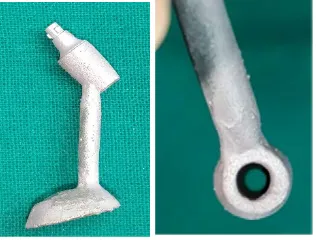
Fig.78: Evaluation of the cast abutment
Fig.79: Trimming of cast abutment
Fig.81: Grouped test samples: GI (1-10) GII (1-10)
Fig.82: Cast abutment held by firing pin
Fig.83: Firing tray placed in firing chamber
Fig.84: 84a: Oxidation firing 84b: Opaque firing 84c: 1st dentine firing 84d: 2nd dentine firing 84e: Glaze firing
Fig.85: Cast abutment subjected to simulated porcelain firing
Fig.86: Group II samples (1-10) after simulated porcelain firing
Fig.87: Securing the abutment to surveying mandrel
Fig.88: 88a: Abutment submerged up to middle of the mold space 88b: Auto polymerizing resin added to middle 3rd of abutment
Fig.89: 89a: Partially embedded abutment 89b: Complete embedding of abutment
Fig.90: Completely embedded abutment in resin block
Fig.91: 91a: Group I samples embedded and numbered from 1-10 91b: Group II samples embedded and numbered from 1-10
Fig.92: Reference line for proper sectioning
93b: Waterjet sectioning of sample
Fig.94: Sectioned sample
Fig.95: 95a: Sectioned Group I samples (1-10) (n=20) 95b: Sectioned Group II samples (1-10) (n=20)
Fig.96: Reduced Sectioned samples for SEM analysis
Fig.97: Electrolytic etching of the sample
Fig.98: Smoothening of sectioned samples using SiC papers
Fig.99: Steam cleaning of sample
Fig.100: Ultrasonic cleaning of samples in distilled water
Fig.101: Drying of prepared test sample
Fig.102: Microstructure of Group I sample in SEM at 17x
Fig.103: Microstructure of Group II sample in SEM at 17x
Fig.104: EDS analysis of Group I sample
Fig.105: EDS analysis of Group II sample
ANNEXURE III
SEM PHOTOMICROGRAPHS
Fig.107: Microstructure of Group I samples in SEM at 100x
Fig.108: Microstructure of Group I samples in SEM at 300x
Fig.109: Microstructure of Group I samples in SEM at 1000x
Fig.110: Microstructure of Group I samples in SEM at 2000x
Fig.111: Microstructure of Group II samples in SEM at 100x
Fig.112: Microstructure of Group II samples in SEM at 300x
Fig.113: Microstructure of Group II samples in SEM at 1000x
ANNEXURE IV
LIST OF GRAPHS
GRAPH NO.
TITLE
I Elemental composition of as received premachined implant abutment base by EDS analysis.
II Elemental composition of as received casting alloy by EDS analysis.
III Elemental composition at Point A (9µm from interface towards the premachined base) by EDS analysis of Group I samples.
IV Elemental composition at Point B (4.5µmfrom interface towards the premachined base) by EDS analysis of Group I samples.
V Elemental composition at Point C (at the interface) by EDS analysis of Group I samples.
VI Elemental composition at Point D (4.5µm from interface towards the cast alloy)by EDS analysis of Group I samples. VII Elemental composition at Point E (9µm from interface
VIII Elemental composition at Point A (9µm from interface towards the premachined base) by EDS analysis of Group II samples.
IX Elemental composition at Point B (4.5µm from interface towards the premachined base) by EDS analysis of Group II samples.
X Elemental composition at Point C (at the interface) by EDS analysis of Group II samples.
XI Elemental composition at Point D (4.5µm from interface towards the cast alloy) by EDS analysis of Group II samples. XII Elemental composition at Point E (9µm from interface
towards the cast alloy) by EDS analysis of Group II samples. XIII Comparative evaluation between mean hardness values at implant abutment base, interface and cast alloy of Group I samples
XIV Comparative evaluation between mean hardness values at implant abutment base, interface and cast alloy of Group II samples
ANNEXURE V
1
INTRODUCTION
Endosteal implants have been commonly used in dental treatment for complete and partial edentulous arches in both the anterior and posterior regions of the mouth for more than 70 years.1 Studies reveal that implants currently have
high clinical success rates exceeding 95%.5, 14, 17, 22, 33, 39
Long term success of implant supported dental restorations requires precise fit between the implant body and the abutment, and continuity between the abutment components.1, 21, 23, 24, 27 Precise fit of these structures prevents the occurrence of deleterious tensile and compressive stresses, as well as excessive bending moments, on the dental implant restorations during functional loading.25, 46, 47Excessive stresses and bending movements may cause loosening
of the prosthesis or abutment screws as well as distortion or breakage of the restoration, micro fractures around the bone surrounding the implant, or fracture of the implant body.46, 47 Besides providing appropriate stress transfer, precise
fit between the implant and implant supported prosthesis results in favourable biologic response of peri-implant host tissues and avoids mechanical complications in the prosthodontic rehabilitation.45
In many partially edentulous patients with limited inter occlusal distance, the concept of UCLA abutments with completely castable plastic sleeve that can be cast to the desired shape and secured directly to the implant fixture, was developed.31 Possible consequence of using cast abutments is screw
loosening, due to a poor fit of abutment to implant with resultant lack of frictional resistance to rotation8, 10, or as a result of casting inaccuracies21, 26 in
the area of the screw seat. It was found that the premachined abutments, are superior in adaptation to those cast from burnout patterns and laboratory finished. 27, 37, 46
To overcome the drawback of complete cast abutments, as well as to obtain clinically precise fit between implants and their superstructures, prefabricated cast on components were introduced to obtain customized cast on abutments for screw retained implant restorations. The cast on component is designed for standard screw retained restorations, and a wide range of cast on structures can be used with implant systems to obtain customized abutment and frameworks.10, 11, 12, 13 Compatible alloys can be fused to the premachined
abutment base by means of compound casting technique.3, 19, 20, 34, 37 Once casting is completed, the cast on component is integrated with the definitive restoration.29, 36, 41
When an alloy was cast to a wrought component, an excellent fit was found between the two alloys.3, 20 Nevertheless, when premachined abutment
3
structures, the premachined wrought alloy implant abutment base and the casting alloy. Metallurgical compatibility of the premachined wrought implant abutment base with the casting alloy is necessary to obtain good mechanical performance of an implant supported fixed restoration.3, 19, 20, 34
Noble alloy premachined implant abutment bases were used most frequently for the cast on abutments, because they are highly compatible with the high noble casting alloys used for the superstructure. Several studies addressing the metallurgical evaluation of interfaces between implant abutment bases and casting alloys report that implant abutment bases of noble alloys are highly compatible with noble casting alloys,10, 13 whereas a titanium alloy implant abutment base is incompatible.12, 13 Various studies have shown
metallurgical compatibility between gold based cast on abutments with high noble and low noble casting alloys with varying heat treatment procedures simulating the ceramic firing cycles. 41, 42, 43 The drawback of using noble alloy
based cast on abutments is the cost of the alloy.
Co-Cr cast on abutments were introduced as an alternate to the expensive gold based cast on abutments. Compared with gold based alloys, Co-Cr alloys have high elastic modulus and significantly lower cost. They also exhibit good corrosion resistance and biocompatibility.2, 32, 49
compatibility between the Cr dental casting alloy and the premachined Co-Cr implant abutment base and the effects of porcelain firing cycles on the interface. The current research hypothesis was that metallurgical compatibility exists between the Co-Cr casting alloy and the Co-Cr premachined implant abutment base.
The objectives of the present study included the following:
1. To evaluate the microstructure of the cast on abutments at the premachined Co-Cr implant abutment base, Co-Cr casting alloy and their interface in as cast condition.
2. To evaluate the microstructure of the cast on abutments at the premachined Co-Cr implant abutment base, Co-Cr casting alloy and their interface after simulated porcelain firing.
3. To evaluate the elemental composition of the cast on abutments at the premachined Co-Cr implant abutment base, Co-Cr casting alloy and their interface in as cast condition.
4. To evaluate the elemental composition of the cast on abutments at the premachined Co-Cr implant abutment base, Co-Cr casting alloy and their interface after simulated porcelain firing.
5
6. To measure the hardness of the cast on abutments at the premachined Co-Cr implant abutment base, Co-Cr casting alloy and their interface after simulated porcelain firing.
7. To compare the microstructure of the cast on abutments at the premachined Co-Cr implant abutment base, Co-Cr casting alloy and their interface in as cast condition and after simulated porcelain firing. 8. To compare the elemental composition of the cast on abutments at the
premachined Co-Cr implant abutment base, Co-Cr casting alloy and their interface in as cast condition and after simulated porcelain firing. 9. To compare the hardness of the cast on abutments at the premachined
Co-Cr implant abutment base, Co-Cr casting alloy and their interface in as cast condition.
10.To compare the hardness of the cast on abutments at the premachined Co-Cr implant abutment base, Co-Cr casting alloy and their interface after simulated porcelain firing.
6
REVIEW OF LITERATURE
Asgar and Peyton (1965)3found that on casting to embedded wires, a
possible contamination of the wire can occur. The object of the study was to investigate the contamination of embedded precious metal wire in investments during casting that reduces the physical properties of the wire and make it weak. The results of this study have led to recommendations for a proper investment material and a suitable burnout cycle to be used in dental practice when alloys to embedded wire are cast. They found that by using carbon di oxide releasing investments and following low heat burnout procedures, the contamination of the embedded wires can be reduced and hence improving the quality of the union formed between cast and wrought metals.
Gilson et al (1965)19 made an investigation to examine the quality of
the union formed between a casting alloy and different mold-included wrought precious metals. They found that the thinner the mold-embedded precious wrought metal plate, the better were the unions achieved and the hotter the mold-embedded metals were at the time of casting, the closer were the unions achieved.
Adell et al (1981)1 installed, 2768 fixtures were in 410 edentulous jaws
maintained by a gentle surgical installation technique, a long healing time and a proper stress distribution when in function.
Lewis (1992)31 reviewed the UCLA abutment that had been in the
restoration of osseointegrated implants. The 4-year success rates were 95.8%. The findings were that, the design of the abutment allows fabrication of the restoration directly to the implant fixture, bypassing the transmucosal abutment cylinder, is valuable in overcoming problems of limited interocclusal distance, interproximal distance, implant angulation, and soft tissue response and improved esthetics.
Weinberg (1993)46 described the principles of force distribution as
applied to diagnosis and treatment of implant-supported prostheses. The biomechanics of force distribution in implant-supported prostheses is qualitatively different than when natural teeth serve as abutments. Because of the relative "flexibility" of the periodontal ligament, force distribution is dependent on teeth and prosthesis. Conversely, because the osseointegrated interface permits no movement, force distribution depends on some deformation of the fixture-abutment-retaining screw complex.
Carr and Brantley (1993)12 compared the interfaces produced by
8
interface specimens produced with alloy cast to noble metal cylinders compared with titanium cylinders.
Carr et al(1993)11 made castings simulating a maxillary central incisor
coping from five representative high-palladium alloys. The microstructures of both specimens were viewed under optical and scanning electron microscope and mean values of Vickers hardness were determined for each alloy. In 3 alloys changes in microstructures were found after heat treatment and regions of oxidation processes were found. Statistically significant decreases in hardness occurred after simulated porcelain firing cycles but relatively small to cause clinical significance.
Kallus and Blessing (1994)25 investigated the possible occurrence of
loose gold and abutment screws retaining full-arch osseointegrated prostheses that had been in use for at least 5 years. The principles of the California Dental Association's (CDA) quality evaluation criteria were modified and applied in the study. Gold screw loosening was found to be related to framework misfit and was considered to be operator dependent to some extent and was recommended that full-arch fixed prostheses be retightened after 5 years.
Brantley et al (1995)7 used x-ray diffraction (XRD) to investigate four
Low-intensity peaks in the Pd-Ga alloys were attributed to small amounts of secondary phases observed in the microstructures.
Carr and Brantley (1996)13, following a previous report that compared
titanium-based implant cylinders and conventional noble metal cylinders from combined with cast noble alloys. The interfaces created by casting both high-fusing and low-high-fusing alloys around the cylinders exhibited a general elemental concentration variability compared with the bulk alloy regions, but continuous concentrations for shared elements suggested alloy-cylinder compatibility. Vickers hardness values decreased from 12% to 43% for the various cylinders after casting. This study suggests characteristics of an ideal cast interface that include maintenance of the cylinder and casting alloy microstructures up to the interface, absence of inter-facial reaction regions, lack of porosity created by volatilization of components from either alloy or the casting process, and sufficient strength to maintain anticipated loads.
Jemt and Book (1996)23 statistically correlated in vivo measurements
10
Jemt and Lekhom (1998)24 used a 3-D photogrammetric technique to
measure distortion of 3unit implant frame-works and bone surrounding osseointegrated implants after securing misfitting superstructures to the implants. Four adult loop-eared rabbits were provided with 3 implants each in the proximal part of 1 tibia each. Measurements and comparisons of the topography of the frame-works and surrounding bone before and after tightening the central screw indicated a complex and inconsistent deformation pattern. Bone deformation was found to be basically localized between the implants, where compressions of about half a millimetre were observed. This concentration of bone deformation as a result of misfit may be one contributing factor to initial marginal bone loss, occasionally observed after insertion of implant supported prostheses.
Eckert and Wollan (1998)17 described results for implant survival,
Byrne et al (1998)8 assessed the adaptation of premachined, cast, and
laboratory modified premachined abutments to implants at two sites: abutment/implant interface and screw to screw seat. The adaptation of abutments to implants was closer and the amounts of contact larger for assemblies with premachined and laboratory modified premachined abutments than for those with cast abutments.
Kan et al (1999)26discussed the passive fit and reviewed the various
clinical methods that have been suggested for evaluating implant framework fit. They found that relative misfit with the available fit evaluation methods cannot be accurately assessed and determined. In this review they found that improving clinical techniques such as the use of rigid impression materials, custom trays, cementable superstructure, and a combination of the available evaluation methods may be relied on to optimize fit or compensate for misfit.
Carotenuto et al (1999)10 did a study to analyse the characteristics of
12
Binon (2000)5 classified and explained about the implants, the abutment
connections, the implant-abutment interface, abutment screw design, wide and narrow diameter implants and platforms, thread design, selection criteria, quality control and validation, and discussed the future of dental implants. Some manufacturers have no published clinical studies or documentation at all.
Watanabe et al (2000)46 compared and analysed the strains created
around the implant bodies screwed with 4 types of implant superstructures. The magnitude of strain produced around a screw-retained implant prosthesis was significantly lower with the passive-fit method when compared to the other 3 fabricating methods. Furthermore, the implants prepared by the passive-fit method were not affected by the order of screw tightening.
Vigolo et al (2000)45 did a study that assessed changes at the implant
interface of gold-machined UCLA abutments after casting and porcelain baking in the case of single-tooth restorations. The results of this investigation suggest that, if all laboratory steps are observed carefully, changes at the implant interface of gold-machined UCLA abutments do not occur.
Sahin et al (2001)37 reviewed the clinical significance of passive fit and
the factors that affect the final fit of implant supported frameworks.They found that absolute passive framework fit has not been achieved in the previous three decades. Obtaining a passive fit did not seem to be possible and may in fact be unnecessary.
Taylor and Agar (2002)39 reviewed the most important aspects of the
success of osseointegration had been gratifying, the scientific basis for what was routinely done and what seemed to work was largely lacking. Empirical concepts and principles based on the treatment of natural teeth had been extrapolated to the treatment of endosseous implants with apparent success.
McGlumpy et al (2003)33 undertook a 5-year prospective study of
HA-coated cylindrical implants placed into patients to determine the long-term clinical performance of the implants. Implant failures were most commonly associated with short implants or angled abutments. The HA-coated cylindric implants in this study provided a predictable means of oral rehabilitation.
Hecker and Eckert (2003)21 did a study to determine whether the fit of
an implant-supported prosthesis changes through cyclic loading and to quantify the amount of change between the gold cylinder and implant abutment over time. Within the limitations of this study, the fit changed when simulated functional loading of the anterior portion of the prosthesis was performed. Simulated functional loading applied unilaterally or bilaterally to the posterior cantilever portion of the prosthesis did not result in changes in the measured gap sizes.
Jeffcoat et al (2003)22 compared the success of hydroxyapatite (HA)
-coated and machined titanium (Ti) implants in a 5-year randomized, controlled clinical trial. All types of implants placed in this study had success rates above 95%. Over 5 years, the success rate tended to favour HA-coated implants.
Oh and Kim (2004)35 investigated the galvanic and crevice corrosion
14
chromium suprastructures used to in combination with titanium (Ti) implants. After electrochemical testing, surface morphologies and cross-sections were examined using micrographs of the samples. Photomicrographs showed crevice or pitting corrosion in the marginal gap and at the suprastructure surface. Of the tested samples Co–Cr/Ti implant couples showed the possibility of galvanic corrosion but, its degree was not significant. However, it should be borne in mind that galvanic corrosion can accelerate localized corrosion, such as crevice or pitting corrosion.
Kano et al (2004)27 compared the marginal accuracy of pre-made
cylinders versus plastic cylinders cast with two different base metal casting alloys and examined for marginal accuracy according to vertical gap, horizontal gap and horizontal gap depth at the abutment/cylinder interface. No statistically significant differences were found between cast groups (1 and 2), but significant better fit was obtained with pre-made metal cylinders when compared to cast cylinders with Ni-Cr and Co-Cr alloys, for all analyses.
Xiaoxia et al (2004)48 studied the interaction between die casting die
Viennot et al (2005)44 made a study in which the corrosion resistance
of a cobalt-chromium (Co-Cr) alloy was assessed with a view to determining its potential use in the manufacture of fixed dental prostheses. The electrochemical behaviour of the alloy was compared with that of two palladium (Pd)-based alloys. All materials showed a very high resistance to corrosion. Given that the beneficial mechanical properties of Co-Cr alloys have already been established, this type of alloy may be a suitable alternative for use in the manufacture of fixed dental prostheses.
Comfort et al (2005)14 determined the 5-year clinical performance of
3.3 mm diameter NP implants. Recognized implant success criteria of mean marginal alveolar bone loss, the placement of prosthesis of satisfactory appearance, and the absence of implant mobility, peri-implant radiolucency, pain, discomfort or infection were used. The mean marginal alveolar bone loss during the first year was 0.41mm. The mean marginal alveolar bone loss between the second and fifth year was 0.03mm. The success rate of NP implants according to a well-established set of criteria was 96%.
Lee et al (2005)30 investigated the effect of pre-heat treatments,
16
Tensile strength slightly decreases with increasing the heat treatment temperature and the heat treatment time, whereas the ductility slightly increases.
The σ phase completely dissolves into matrix when the alloy is heat-treated at 1260C for longer than 6 h.
Zupanic et al (2006)49 did a study to determine which joining method
offers the best properties to cobalt- chromium alloy frameworks. Brazed and 2 types of laser-welded joints were compared for their mechanical and corrosion characteristics. They found that Laser welding provides excellent corrosion resistance to cobalt-chromium alloy joints, but strength is limited due to the shallow weld penetration. Brazed joints are less resistant to corrosion but have higher tensile strength than laser welds.
Kano et al (2007)28 evaluated the effect of casting procedures on
rotational misfit of cast abutments when compared to machined titanium abutments. Rotational misfit between the external hexagon of the implant and internal hexagon of the abutments were evaluated. Rotational misfit was less than 2 degrees for all groups except for cast Co-Cr abutments, which demonstrated a significantly greater rotational misfit.
Al-Hitty et al (2007)2 made a study to assess in vitro the resistance to
approach to predict the corrosion behaviour of dental alloys by firstly using the easier methods.
Vergos and Papadopoulos (2008)43 investigated the interface between
two dental alloys cast-to a prefabricated gold cylinder in two thicknesses (1, 2mm). Specimens were observed in optical and scanning electron microscopes. The boundaries between the cylinder and the cast-to alloys were distinct. Line scan analysis revealed the gradual diffusion of the main elements of each alloy in the structure of the gold cylinder and vice-versa in a 3–5µm zone.
do Nascimento et al (2009)16 used the checkerboard DNA–DNA
hybridization method for detection and quantitation of bacteria from the internal parts of dental implants and to compare bacterial leakage from implants connected either to cast or to pre-machined abutments. They found that bacterial leakage through the implant–abutment interface does not significantly differ when cast or pre-machined abutments are used.
Ucar et al (2009)41 did a study to characterize as-received cast-to
components from 5 manufacturers. They found that the elemental compositions, microstructures, and Vickers hardness of the 5 as-received cast-to implant components were similar. Because both microstructural bands principally contain gold, palladium, and platinum, these noble cast-to implant components should be metallurgically compatible with noble metal casting alloys.
Nami et al (2010)34 investigated the diffusion bonding of Al/Mg2Si
metal matrix composite (MMC) using Cu interlayer at optimal bonding
18
layers exist at the bond region depending on the bonding duration. The shear strength of joints increased with bonding duration due to elimination of CuAl2 brittle diffusion layer.
Hajjari et al (2011)20 compound casted Al/Mg couples using each of
the aluminum and magnesium molten metal cast around solid cylindrical inserts of the other metal. Scanning electron microscope showed that in the case of casting aluminum melt around a magnesium insert, a gap is formed at the interface, while in the process of casting magnesium melt around an aluminum insert, a relatively uniform interface composed of three different layers is formed at the interface. These three layers are mainly composed of high-hardness Al–Mg intermetallic compounds. The results of shear strength tests obviously showed that the strength of the interface depends on the interface thickness and increases by decreasing the thickness of the interface.
Ucar et al (2011)42 did a study to investigate the interfacial regions of a
representative noble implant component and 6 cast noble dental alloys and to evaluate the effects of porcelain firing cycles on the interface. The effects of porcelain firing cycles on microstructures, diffusion, hardness, and phases were also evaluated. Microstructures of bulk alloys were predominantly maintained to a well-defined boundary for both as-cast and heat-treated conditions. They found that Less expensive noble alternatives to high-gold alloys provided comparable metallurgical compatibility with the noble implant component.
Lalithamma et al (2014)29 compared the marginal accuracy of premade
revealed no significant difference in mean marginal microgap between premade gold and titanium abutments and between premade stainless steel and cast titanium abutments. Statistically significant differences (P = .001) were found among all other groups.
Tuna et al (2015)40 evaluated the electrochemical corrosion resistance
of Co-Cr alloy specimens that were fabricated by conventional casting, milling, and laser sintering. The specimens fabricated with 3 different methods were investigated by potentiodynamic tests and electrochemical impedance spectroscopy in an artificial saliva. The corrosion resistance of a Co-Cr alloy specimens fabricated by milling or laser sintering was greater than that of the conventionally cast alloy specimens.
Luchetti et al (2015)32 conducted an in vitro study was to evaluate the
ion release of chromium, cobalt, and iron from the Co-Cr alloys used for traditionally cast and computer-aided design/computer-aided manufacturing dental devices after interaction with oral bacteria and different pH conditions. Concluded that with the exception of casting alloy under acidic conditions, no significant differences were found, even after exposure to bacteria.
Ozkomur et al (2016)36 did an in vitro study to evaluate the
MATERIALS AND METHODS
The present in vitro study was conducted to comparatively evaluate the interface formed by the premachined Co-Cr implant abutment bases with cast on Co-Cr alloy in as-cast and simulated porcelain firing conditions.
The following materials, instruments, equipment and methodology were employed:
Materials used for the study:
• Polyvinylsiloxane impression material (Aquasil, Dentsply, Germany) (Fig.1)
o Putty consistency, regular set (Fig.1a)
o Light body consistency, regular set (Fig.1b)
• Bard Parker blade (Glassvan, India) (Fig.2)
• Laboratory implant replica (Equinox Medical Technologies BV, Netherlands) (Fig.3)
• Clear auto polymerizing acrylic resin (RR Cold Cure, DPI, India) (Fig.4)
• Screw retained engaging cast on abutment with premachined Co-Cr implant base (Myriad-Plus Resolve cast to base abutment, Equinox Medical Technologies BV, Netherlands) (Fig.5)
• Inlay casting wax (GC, America) (Fig.6)
21
• Auto polymerizing acrylic resin (Pattern Resin, GC, America) (Fig.8)
• Wax sprue wire 2.5mm (BEGO, Germany) (Fig.9)
• Surfactant (Aurofilm, BEGO, Germany) (Fig.10)
• Graphite free phosphate bonded investment (Bellasun, BEGO, Germany) (Fig.11)
• Colloidal silica (Begosol, BEGO, Germany) (Fig.12)
• Distilled water (Merck & Co., Mumbai, India) (Fig.13)
• 0.8mm beading wire (BEGO, Germany) (Fig.14)
• Nickel and Beryllium free cobalt chromium casting alloy pellets (Wirobond® 280, BEGO, Germany) (Fig.15)
• Aluminum oxide powder (110µm) (Korox, BEGO, Germany) (Fig.16)
• Silicon carbide emery papers (3M India Ltd., Bangalore, India) (Fig.17)
• Polishing cloth (Fig.18a)
• Aluminum oxide paste (Fig.18b)
• Ethyl alcohol 100% (Merck & Co., Mumbai, India) (Fig.19a)
• Hydrochloric acid 35% (Merck & Co., Mumbai, India) (Fig.19b)
• Hydrogen peroxide (Rajkumar Enterprises, Chennai, India) (Fig.19c)
• Oxalic acid (Merck & Co., Mumbai, India) (Fig.19d)
Instruments employed in the study:
• Auto mixing spiral tip (Yellow 70mm, Adenta, USA) (Fig.20b)
• Bard Parker No.3 handle (Hebbar surgical, Chennai, India) (Fig.21)
• Spirit level indicators (Jinhua Hengda tools, China) (Fig.22)
• Hand screw driver (Equinox Medical Technologies BV, Netherlands) (Fig.23)
• Metal scale (Fig.24)
• Carborundum disc with mandrel(Fig.25)
• P K Thomas instruments (Fig.26)
• Dappen dish (Samit Products, New Delhi, India) (Fig.27)
• Tungsten carbide burs (Edenta, Switzerland) (Fig.28)
• Crucible former and silicone ring for investment (Sili Ring, Delta Labs, Chennai) (Fig.29)
• Straight artery forceps (Fig.30)
Equipment employed in the study:
• Dental surveyor (Saeshin Precision Ind. Co., Korea) (Fig.31)
• Micro motor, Straight hand piece (Marathon, Saeyang, Korea) (Fig.32)
• Vacuum mixer (Whipmix, Kentucky, USA) (Fig.33)
• Burnout furnace (Technico, Ind products, Chennai) (Fig.34)
• Oxy acetylene torch (Unident Instruments, New Delhi, India) (Fig.35)
23
• Sandblasting unit (Delta labs, Chennai, India) (Fig.37)
• Steam cleaner (Confident dental equipment Ltd., India) (Fig.38)
• Ceramic furnace (Vita V60 i-Line, Vita, Germany) (Fig.39)
• Water jet powered sectioning machine (Germany) (Fig.40)
• High speed lathe (Alloy grinder, Demco, California, U.S.A) (Fig.41)
• Ultrasonic cleaner (Beijing Ultrasonic Co., China) (Fig.42)
• Dryer (Panasonic Corp., Thailand) (Fig.43)
• Scanning electron microscope (S-3400N, Hitachi High Technologies Corporation, Japan) (Fig.44)
• Vickers hardness testing machine (MVD 402TS, HDNS Kelly Instruments, Shanghai, China) (Fig.45)
Description of water-jet machine:
Line Diagram of Water-jet Machine:
Description of Scanning electron microscope:
25
surface charging, the sample is coated with a conductive material to give the electrons a path to leave the sample. The test sample is then loaded on to the stage in the specimen chamber. The chamber door is closed and air evacuated. The test sample is then brought into focus and using the auto focus and auto alignment option, the center of the sample is determined. The image on the monitor is captured and saved using PC-SEM software.
METHODOLOGY
The present in vitro study was conducted to analyze the interface formed by premachined cobalt chromium implant abutment bases with cast on cobalt chromium alloy before and after simulated porcelain firing.
The methodology followed in this study consisted of the following steps: I. Fabrication of stainless steel block and receptacle
II. Fabrication of putty index for resin block. III. Embedding implant replica in resin block.
IV. Securing the premachined implant abutment base with the implant replica. V. Fabrication of screw retained Co-Cr implant abutments by compound
casting technique.
A. Fabrication of wax pattern.
B. Fabrication of auto polymerizing resin pattern. C. Spruing procedure
D. Investing procedure. E. Burnout procedure. F. Casting procedure.
G. Divesting and trimming of the casted abutments. VI. Grouping of cast on abutments.
27
IX. Sectioning of abutments using waterjet machine. X. Preparation of the sectioned test samples.
XI. Microstructural analysis of the samples using Scanning electron microscope (SEM).
XII. Analysis of elemental composition by Energy Dispersive Spectroscopy (EDS)
XIII. Measurement of hardness by Vickers hardness test. XIV. Tabulation of results and statistical analysis.
I. Fabrication of stainless steel block and receptacle (Fig.46,47):
A steel block measuring 27 mm X 27 mm X 18 mm (Raja Industries, Chennai) (Fig.46) was custom made for the purpose of creating a uniform putty index of standardized dimensions to aid in the embedding of the implant replica.
A custom made, stainless steel, perforated metal receptacle of dimensions 40mm X 40 mm X 40 mm (Raja Industries, Chennai) (Fig.47) was fabricated to act as a customized impression tray. This receptacle served as a matrix for holding silicone impression material to obtain the required putty index.
II. Fabrication a resin base to hold the implant replica (Fig.48,49):
This mixed putty dough was placed inside the stainless-steel receptacle (Fig.48a). Light body material in a cartridge was attached to the auto mixing gun (Heraeus Kulzer, Dormagen, Switzerland) (Fig.20a). A spiral mixing tip (yellow 70mm, Adenta, USA) (Fig.20b) was attached to the cartridge tip and the material was injected gently over the custom made steel block (Fig.48b). The steel block was then centered and impressed into the soft putty such that the top surface of the block was in flush with the top edge of the receptacle (Fig.49a). The impression material was smoothened and left undisturbed until set and excess material was removed using a Bard Parker blade (Glassvan, India) (Fig.2) and handle (Hebbar surgical, Chennai, India) (Fig.21). The steel block was removed from the index (Fig.49b) and was used to fabricate the resin block to secure the implant replica.
III. Embedding implant replica in resin block (Fig. 50-54):
29
Auto polymerizing clear acrylic resin (Cold Cure, DPI, India) (Fig.4) was poured into the putty index up to its upper margin (Fig.53) and was allowed to polymerize and left undisturbed. Upon setting, the implant replica was released from the surveying mandrel and the resin base was carefully retrieved (Fig.54).
IV. Securing the premachined implant abutment base with the implant replica (Fig.55, 56):
The premachined cast on implant abutment consisted of a Co-Cr base and a plastic cylinder (Equinox Medical Technologies BV, Netherlands) (Fig.5). The premachined Co-Cr implant abutment base was engaged to the implant replica embedded in the resin base (Fig.55). The abutment base was secured tight to the implant replica with an abutment screw by finger tightening (Fig.56) using a Prosthetic Hex screw driver (Equinox Medical Technologies BV, Netherlands) (Fig.23).
V. Fabrication of screw retained Co-Cr implant abutments by compound casting technique (Fig.57 – 80):
A. Fabrication of wax pattern (Fig.57 – 59):
P.K. Thomas carving instruments (Fig.26). One custom wax pattern was thus fabricated to simulate the configuration of an 8mm high cylinder(Fig.59).
B. Fabrication of resin pattern (Fig.60 – 63):
In order to standardize the thickness of the patterns for all abutments to be fabricated, an index of the wax pattern was made using addition silicone. The screw access channel of the plastic cylinder was blocked with modelling wax (The Hindustan Dental Products, Hyderabad, India) (Fig.7) to prevent silicone entry while making the index (Fig.60a). The base and catalyst of the silicone putty were mixed and loaded into a glass dappen dish (Samit Products, New Delhi, India) (Fig.27) (Fig.60b). The index was made by impressing the wax pattern into the silicone putty loaded in the dappen dish (Fig.60c). After setting the index was removed from the dappen dish and checked for acceptability (Fig.60d).
31
C. Spruing procedure (Fig.64 – 66):
Direct Spruing technique was followed. The premachined Co-Cr implant abutment base with the resin pattern was connected to wax sprue wire of 2.5mm thickness (BEGO, Germany) (Fig.9) to the thickest portion of the pattern at an angle of 45 degrees (Fig.64). The other end of the sprue was attached to the crucible former (Fig.65). A silicone ring was placed over the crucible former (Sili Ring, Delta Labs, Chennai, India) (Fig.29). A minimum distance of 6mm was maintained from the top of the ring to the margin of pattern (Fig.66).
D. Investing procedure (Fig.67 – 69):
minutes as per manufacturer’s recommendation. In a similar manner, all 20 resin patterns were invested.
E. Burnout procedure (Fig.70, 71):
After 20 minutes of bench setting time, the silicone ring was removed. The set investment was placed in a burnout furnace (Technico, Ind Products, Chennai) (Fig.34) in a slanting position with the crucible end contacting the floor for escape of melted sprue wax (Fig.70). The resin patterns were subjected to pre-heating technique in burnout furnace at temperature of 450°C for 30 minutes (Fig.71a). Then the investment was continuously heated up to 950°C at the rate of 8°C/min in the burnout furnace (Fig.71b). The investment mold was reversed later near the end of the burnout cycle with the sprue hole facing upward to enable the escape of entrapped gases and allow oxygen contact to ensure complete burnout of the resin patterns and allow for mold expansion.
F. Casting procedure (Fig.72 – 74):
33
rotated 3 rounds to provide the required momentum by spring action. The alloy pellets were melted using an oxy-acetylene flame torch (Unident Instruments Pvt. Ltd., New Delhi, India) (Fig.35) using the reducing zone of the flame to eliminate the formation of oxides during melting (Fig.73). Once the alloy was melted, the spring was released to allow the rotation of the broken arm at a speed of 2000 rpm and the casting was completed by centrifugal action (Fig.74). In a similar manner all the 20 castings were performed.
G. Divesting and trimming of casted abutment (Fig.75– 80):
After the casting procedure, the investment mold filled with the cast alloy was removed and placed on a heat-resistant stone and was allowed to cool to room temperature (Fig.75). Divesting was done to retrieve the compound cast abutments from the investment (Fig.76). Care was taken to prevent damage to the premachined abutment bases and the casted component. Investment residue was removed from the casted mold by sand blasting (Delta Labs, Chennai, India) (Fig.37) with 110µm Aluminum oxide powder (Korox, BEGO, Germany) (Fig.16) at 80 psi pressure (Fig.77). The casting was thoroughly inspected for any casting defects (Fig.78a, 78b). With the help of carborundum disc the sprue was sectioned at the junction of the attachment. The casting was trimmed using tungsten carbide burs (Fig.79) and cleaned using a steam cleaner (Confident Dental Equipment Ltd., India) (Fig.38).
VI. Grouping of cast on abutments (Fig.81):
The 20 compound cast Screw retained Co-Cr cast on implant abutments were evaluated for acceptability. Samples with casting defects like voids were eliminated and only those with good casting continuity with the premachined base were included in this study. They were randomly divided into two groups, Group I and Group II with 10 samples in each group. Group I samples (as cast) were not subjected to simulated porcelain firing while Group II samples were subjected to simulated porcelain firing. The samples were numbered as Group I (1- 10) and Group II (1 – 10) (Fig.81).
35
Similarly, all 10 samples of Group II1-10 were subjected simulated porcelain firing (Fig.86).
VIII. Embedding of abutments in auto polymerizing acrylic resin (Fig 87 – 91):
The silicone putty index previously obtained was stabilized as done before. One abutment was positioned into the putty index at a given time. The abutment was secured to the surveying mandrel (Fig.87). This was done to orient and center the abutment into the putty index such that, the abutment was submerged up to the middle of the putty index up to the middle third of the abutment (Fig.88a).
Auto polymerizing clear acrylic resin was poured into the putty index up to the middle third of the abutment and then allowed to polymerize and left undisturbed (Fig.88b). Upon setting the abutment was released from the surveying mandrel (Fig.89a). The remaining part of the abutment was completely embedded using auto polymerizing clear acrylic resin and allowed to cure completely (Fig.89b). The resin block with the embedded abutment was carefully retrieved from the silicone index and numbered(Fig.90). In this manner all abutments were embedded individually within clear auto polymerizing resin blocks and numbered accordingly as Group I1-10 and Group II1-10 (Fig.91a, 91b).
vertically sectioned test sample (Fig.92). Each test sample was sectioned vertically using a water jet powered sectioning equipment (Waterjet, Germany) (Fig.40). The test sample was held tightly with clamp in the catch tank (Fig.93a). The controlling unit was used to adjust the pressure. Water mixed with special grade silica as an abrasive agent was focused on the area of sectioning using a 1.0 mm nozzle tip. The test samples were sectioned using water and abrasive under 3500 bar pressure (Fig.93b). Two sections for each sample were thus obtained and labelled as (a) and (b) (Fig.94). Similarly, 20 test samples of group I and II were sectioned and a total of 40 sections were obtained (Fig.95a, 95b).
X. Preparation of the sectioned test samples (Fig.96–101):
37
electrolytic bath containing a mixture hydrochloric acid (Merck and Co., Mumbai, India) (Fig.19b) hydrogen peroxide (Rajkumar Enterprises, Chennai, India) (Fig.19c) and oxalic acid (Merck and Co., Mumbai, India) (Fig.19d) under 5mV for 10 seconds (Fig.98). The samples were then cleaned (Fig.99) using a steam cleaner and followed by cleaning in ultrasonic bath of distilled water and 100% Ethyl alcohol (Merck and Co., Mumbai, India) (Fig.19a) (Beijing Ultrasonic Co., China) (Fig.42) for 10 minutes (Fig.100) to remove clogged debris that would interfere with the accurate visualization of the interface region. Finally, all the test specimens were held using artery forceps (Fig. 30) and dried with a dryer (Panasonic corporation, Thailand) (Fig.43) to ensure completely cleaned and dry test specimens (Fig.101). The cleaned specimens were now ready for microstructural analysis under SEM.
XI. Microstructural analysis of the samples using Scanning electron microscope (SEM) (Fig. 102,103).
magnification of ×17 (Fig.102, 1 03). Using a variety of higher magnifications x100, x300, x1000, ×2000, secondary electron (SE) images were obtained to show the continuity of the interface, any interfacial reaction regions or porosities and the individual phases in the etched microstructures.
XII. Analysis of elemental composition using Energy Dispersive Spectroscopy (EDS) (Fig. 104,105).
Elemental composition of a new as received premachined Co-Cr implant abutment base and as received Co-Cr casting alloy pellet were first analyzed by energy dispersive spectroscopy.
39
• Point A – 9µm form the interface towards the premachined abutment base.
• Point B – 4.5µm form the interface towards the premachined abutment base.
• Point C – at the interface
• Point D – 4.5µm form the interface towards the cast alloy.
• Point E – 9µm form the interface towards the cast alloy.
The concentration of each element at Points A, B, C, D and E were measured and tabulated.
XIII. Measurement of hardness using Vickers hardness test (Fig.106): Sectioned samples labelled “b” of Group I and II were measured for the hardness at the premachined implant abutment base, the cast on alloy, and the interfacial region using Vickers Hardness testing machine (MVD 402TS HDNS Kelly Instruments, Shanghai, China) (Fig.45). Three indentations for each location per samples was done for appropriate measurements values. A 500gram load with a 5 second dwell time was used to measure the hardness (Fig.106). Similarly, hardness values for all 20 samples were recorded and tabulated.
XIV. Tabulation of results and statistics:
ANNEXURE I
METHODOLOGY OVERVIEW
Tabulation of results and statistical analysis. Measurement of hardness by Vicker’s hardness test.
Analysis of elemental composition by Energy Dispersive Spectroscopy (EDS)
Microstructural analysis of the samples using Scanning electron microscope (SEM).
Preparation of the sectioned test samples. Sectioning of abutments using waterjet machine. Embedding of abutments into auto polymerizing acrylic resin.
Simulated porcelain firing of Group II cast on abutments. Grouping of cast on abutments.
Group I – As cast abutments (n=10)
Group II – Abutments for Simulated porcelain firng (n=10)
Divesting and trimming of the casted abutments.
Fabrication of screw retained Co-Cr implant abutments by compound casting technique (n=20).
Securing the premachined implant abutment base with the implant replica. Embedding implant replica in resin block.
ANNEXURE II
MATERIALS
Fig.1: Polyvinylsiloxane impression material a. Putty consistency, regular set b. Light body consistency, regular set
Fig.2: Bard Parker blade No.15
Fig.3: Laboratory implant replica
[image:68.595.249.346.559.735.2]Fig.4: Clear auto polymerizing acrylic resin
Fig.5: Screw retained engaging cast on implant abutment with premachined Co-Cr base
Fig.7: Modelling wax
Fig.8: Auto polymerizing acrylic resin
Fig.10:Surfactant
Fig.12:Colloidal silica
Fig.14:0.8mm beading wire
Fig.15:Nickel and Beryllium free Cobalt chromium casting alloy pellets
Fig.17:Silicon carbide emery papers
Fig.18:a: Polishing cloth b: Aluminum oxide paste
Fig.19:a: Ethyl alcohol 100%, b: Hydrochloric acid 35% c: Hydrogen peroxide d: Oxalic acid
a
b
c d
INSTRUMENTS EMPLOYED
Fig.20:a: Dispensing gun, b: Auto mixing spiral tip
Fig.21:Bard Parker handle No.3
Fig.22:Spirit level indicators
a
Fig.23:Hand screw driver
Fig.24:Metal scale
Fig.26:P K Thomas instruments
Fig.27:Dappen dish
Fig.29:Crucible former and silicone ring for investment
Fig.30:Straight artery forceps
EQUIPMENT EMPLOYED
Fig.32:Micro motor, straight hand piece
Fig.33:Vacuum mixer
Fig.35:Oxy-Acetylene flame torch
Fig.36:Broken arm centrifugal casting machine
Fig.38:Steam cleaner
Fig.40:Water jet powered sectioning machine
Fig.42:Ultrasonic cleaner
Fig.43:Dryer
METHODOLOGY
I. Fabrication of stainless steel block and receptacle
Fig.46:a: Custom made stainless steel block
b: Line diagram of custom made stainless steel block
Fig.47:a: Custom made stainless steel perforated metal receptacle b: Line diagram of custom made stainless steel perforated metal
receptacle
II. Fabrication of putty index for resin block
Fig.48:a: Loading mixed putty b: Injecting light body material.
Fig.49:a: Impressed Steel block b: Mold space index
Fig.50:Stabilized mold space index
a b
III. Embedding implant replica in resin block
[image:87.595.260.338.163.326.2]Fig.51:Secured implant replica in surveying mandrel
[image:87.595.225.371.366.458.2]Fig.52:Secured implant replica in the mold space
Fig.53:Addition of auto polymerizing clear acrylic resin
[image:87.595.225.371.498.585.2]IV. Securing the premachined implant abutment base with
implant replica
[image:88.595.248.350.200.311.2]Fig.55:Engaging the abutment base with the implant replica
Fig.56:Securing the abutment base with implant replica
V. Fabrication of screw retained Co-Cr implant abutments by
compound casting technique
A. Fabrication of wax pattern
[image:88.595.259.338.350.485.2]Fig.58:Fabrication of the wax pattern
Fig.59:Finished wax pattern