RFID SMART ROOM
ADIBAH BINTI ABU BAKAR
This report is submitted in partial fulfillment of the requirements for the award of Bachelor of Electronic Engineering (Industrial Electronics) With Honours
Faculty of Electronic and Computer Engineering Universiti Teknikal Malaysia Melaka
UNIVERSTI TEKNIKAL MALAYSIA MELAKA
FAKULTI KEJURUTERAAN ELEKTRONIK DAN KEJURUTERAAN KOMPUTER BORANG PENGESAHAN STATUS LAPORAN
PROJEK SARJANA MUDA II
Tajuk Projek : RFID SMART ROOM
Sesi
Pengajian : 2008/2009
Saya ADIBAH BINTI ABU BAKAR mengaku membenarkan Laporan Projek Sarjana Muda ini disimpan di Perpustakaan dengan syarat-syarat kegunaan seperti berikut:
1. Laporan adalah hakmilik Universiti Teknikal Malaysia Melaka.
2. Perpustakaan dibenarkan membuat salinan untuk tujuan pengajian sahaja.
3. Perpustakaan dibenarkan membuat salinan laporan ini sebagai bahan pertukaran antara institusi pengajian tinggi.
4. Sila tandakan ( √ ) :
SULIT*
(Mengandungi maklumat yang berdarjah keselamatan atau kepentingan Malaysia seperti yang termaktub di dalam AKTA RAHSIA RASMI 1972)
TERHAD* (Mengandungi maklumat terhad yang telah ditentukan oleh organisasi/badan di mana penyelidikan dijalankan)
TIDAK TERHAD
Disahkan oleh:
__________________________ ___________________________________
(TANDATANGAN PENULIS) (COP DAN TANDATANGAN PENYELIA)
Alamat Tetap: 11-A, GERBANG PEKAKA,
TAMAN TRANS KRIAN,
14300 NIBONG TEBAL, PULAU PINANG
“I hereby declare that this report is the result of my own work except for quotes as cited in the references.”
“I hereby declare that I have read this report and in my opinion this report is sufficient in terms of scope and quality for the award of Bachelor of Electronic Engineering
(Industrial Electronics) With Honours.”
Signature :……….
ACKNOWLEGDEMENT
ABSTRACT
ABSTRAK
TABLE OF CONTENTS
CHAPTER TITLE PAGE
PROJECT TITLE i
VERIFICATION OF REPORT STATUS ii
DECLARATION iii
SUPERVISOR’S VERIFICATION iv
DEDICATION v
ACKNOWLEDGEMENT vi
ABSTRACT vii
ABSTRAK viii
TABLE OF CONTENTS ix
LIST OF TABLES xii
LIST OF FIGURES xiii
LIST OF ABBREVIATION xv
LIST OF APPENDICES xvi
1 INTRODUCTION
Project Overview 1
Problem Statement 2
Project Objectives 2
Scope of Work 3
Methodology 5
RFID 8
Frequency and Wavelength 10
High-Frequency RFID System 11
Radio Communication Risk 13
Deciding On Frequency Used
Read Range 14
Read Speed 14
Opaque Materials 14
Cost 15
Components of an RFID System Tags
Active Tags and Passive Tags 16
Antenna 17
Readers 19
Challenges and Issues in RFID
Privacy Concern 19
Security 20
Integration with Legacy System 20
2.1.7 Advantages of RFID 21 2.1.8 RFID over Barcodes 21 2.1.9 Collision in RFID 22
2.2 Comparison with the Previous Project 23
2.3 Smart Card 24
2.4 RFID Micro RWD (Mifare) Reader 26
2.4.1 Method of Operation 29
2.4.2 Mifare Transponder Cards 29
2.4.4 Mifare Application and Security 30
2.5 PIC16F876 31
2.5.1 PIC16F876 Pin Out 32
2.5.2 Analog-to-Digital Converter (A/D)Module 33
2.6 LM 35 Temperature Sensor 33
3 METHODOLOGY
3.1 Project Block Diagram 36
3.2 Project Flow Chart 38
3.3 Reader-Card Communication 39
3.4 Reader’s Operation Flow Chart 40
3.5 Micro RWD Circuit Description 41
3.6 Micro RWD Block Diagram 42
4 PRELIMINARY RESULT AND DISCUSSION
4.1 RFID Reader 44
4.1.1 Reader Read Range 45
4.2 Lamp and Fan Circuit 45
4.3 Temperature Sensor and LCD Display 46
4.4 LM 35 Temperature Sensor 47
4.5 Project Analysis 49
5 CONCLUSION AND SUGGESTIONS
5.0 Conclusion 51
REFERENCES 53
LIST OF TABLES
NO TITLE PAGE
2.1 Frequency Range and Wavelength 11
2.2 Frequency Characteristics’ Summary 12
2.3 About a Smart Card 25
LIST OF FIGURES
NO TITLE PAGE
1.1 Project Block Diagram (i) 3
1.2 Project Block Diagram (ii) 3
1.3 Project Flow Chart 5
1.4 System Operation Flow Chart 6
2.1 Simplified view of data transfer in low-frequency passive RFID 9 tags
2.2 Antenna’s Operation 18
2.3 Example of Tags and Antenna 18
2.4 Chip Components 26
2.5 Micro RWD Module 27
2.6 Micro RWD Base Board 27
2.7 RWD Modes of Operation 27
2.8 RWD Schematic to connect to the PIC Microcontroller 28
2.9 Mifare 1K Smart Card 29
2.10 PIC16F876 Pin Diagram 31
2.11 PIC 16F876 Process Block Diagram 32
2.12 LM 35 Temperature Sensor Package 34
2.13 Basic Centigrade Temperature Sensor 34
2.14 Minimum Supply Voltage vs Temperature Graph 35
3.2 Project Block Diagram (ii) 37
3.3 Project Flow Chart 39
3.4 Reader’s Operation Flow Chart 41
3.5 RWD Block Diagram 42
4.1 RFID Reader and its tag detection 45
4.2 Lamp and fan circuit with RFID input 46
4.3 Temperature sensor and LCD circuit 47
4.4 The multimeter reading before additional heat applied 48 4.5 The multimeter reading after additional heat applied 48
LIST OF ABBREVIATIONS
RFID - Radio Frequency Identification
ID - Identification
LCD - Liquid Crystal Display
DC - Direct Current
RF - Radio Frequency
MF - Mifare
LED - Light Emitting Diode
RWD - Readable and Writable Device
MCU - Microcontroller
I/O - Input and Output
CLKIN - Clock IN
CLKOUT - Clock OUT
CPU - Central Processing Unit UID - Unique Identification ADC - Analog to Digital Converter Tx - Transmitter
LIST OF APPENDICES
NO TITLE PAGE
A1 Microcontroller Programming – Lamp and Fan 55
A2 Microcontroller Programming – Temperature Sensor and LCD 63
B PIC16F87X Data Sheet 69
CHAPTER 1
INTRODUCTION
1.0 Project Overview
RFID technology is quite similar with the well known bar codes technology that is based on light waves. Unlike light waves, radio waves readily penetrate most materials. They pass easily through paper, cardboard, wood, cloth, plastic, leather and corn flakes. This is the key advantage RFID tags have over barcodes. The RFID tags can be read without having to be within direct view of the reader. An RFID tag in a well-designed system can be read automatically as it passes by the reader, without human intervention.
will communicate to a microcontroller which controls the room settings based on the ID information. Each ID will have its own user preferences for room lighting and temperature. The users’ preferences are optional. For room lighting, the options are ON and OFF and for room temperature, the options are high, and low.
There is also a temperature sensor that will sense the current room temperature and display it on the LCD screen.
1.1 Problem Statement
There are many technologies used to create a better living environment, but most of them usually require actual contacts. This might be a problem for the disables and old people and also people on a wheelchair since they need to go to the appliances and turn it on themselves. RFID Smart Room is one of the solutions for this problem. This Smart Room will adjust the light and temperature settings according to the users’ preferences without having contact with the appliances. The settings are controlled by the microcontroller that will be programmed to do so. Users have to carry a tag that has a specific ID, and when the reader detects the tag, it will get the information. The information then will be passed to microcontroller which will do all the other processes (controlling the temperature and lighting).
1.2 Project Objectives
Tag
Antenna
Reader PIC
Microcontroller 1
Fan
Lamp
PIC Microcontroller
2 LCD
Temperature Sensor
room lighting and temperature according to each ID.
Second objective is to prioritize one user when reading he card and changing the room settings. This is to avoid reader collision in the RFID system. There is anti-collision algorithm included in the microcontroller programming.
1.3 Scope of Work
Figure 1.1 Project Block Diagram for RFID Reader
The scope of work consists of RFID tags, antenna, RFID reader, temperature sensor, PIC Microcontroller, LCD, a fan (DC Motor) and a lamp.
The tag will interact with the reader through the antenna. Each tag will has its own ID number. Two tags will be used for two users. If both tags come within the read range simultaneously, only one tag will be read first according to the priority. The read/write device antenna connects along with the reader. The antenna will transmit signal and alternating power wave and receives a feedback from the tags. Antenna that used has a frequency of 13.56 MHz.
RS232 connection is used for the reader and microcontroller interface. Reader receives the information from the tag and it will pass the information to the microcontroller for processing.
Temperature sensor used in this project is LM35. It detects the current room temperature and passes the information to the microcontroller. The sensor interfaced the PIC Microcontroller using C language. PIC Microcontroller is the heart of the system. It controls all processes. Settings of all users will be stored in this microcontroller. It will control the outputs and receives information from the reader, and temperature from the temperature sensor. The outputs in this system are DC Motor, lamp and LCD. PIC Microcontroller is programmed using C language.
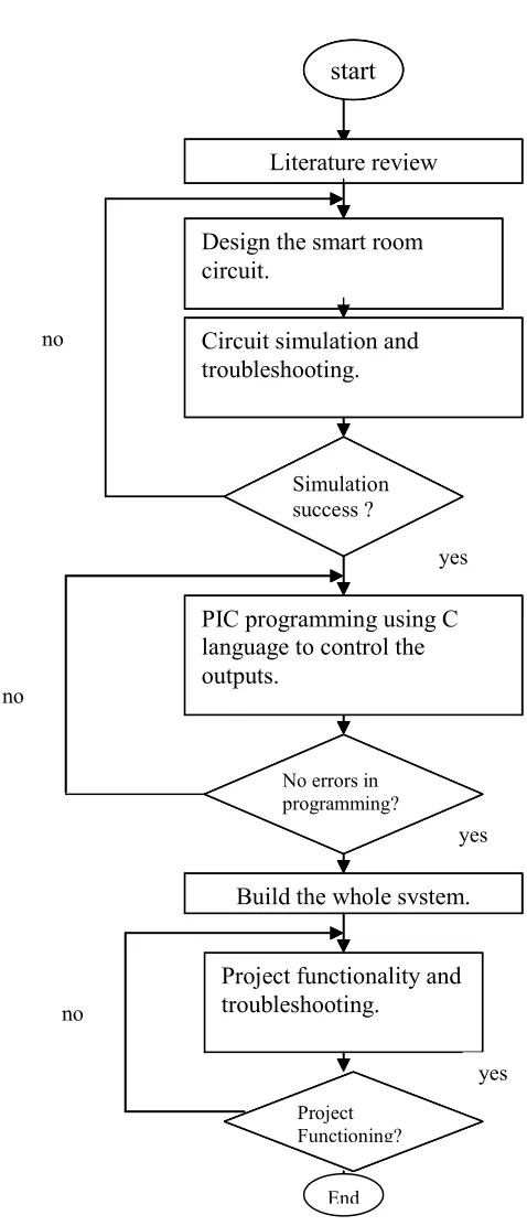
Figure 1.2 Project Flow Chart start
Literature review
Design the smart room circuit.
Circuit simulation and troubleshooting.
Simulation success ? no
Build the whole system.
No errors in programming?
PIC programming using C language to control the outputs.
Project functionality and troubleshooting. yes yes yes no no Project Functioning? start Literature review
Design the smart room circuit.
Circuit simulation and troubleshooting.
Simulation success ? no
Build the whole system.
No errors in programming?
PIC programming using C language to control the outputs. yes yes yes no Project Functioning?
Project functionality and troubleshooting.
no
start
Literature review
Design the smart room circuit.
Circuit simulation and troubleshooting.
Simulation success ? no
Build the whole system.
No errors in programming?
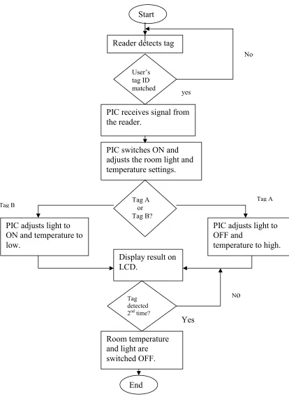
Figure 1.3 System Operation Flow Chart Start
Reader detects tag
PIC receives signal from the reader.
User’s tag ID matched
PIC switches ON and adjusts the room light and temperature settings.
Tag A or Tag B?
PIC adjusts light to OFF and
temperature to high. PIC adjusts light to
ON and temperature to low.
Display result on LCD. yes No Tag A Tag B Tag detected 2nd time?
Room temperature and light are switched OFF.
Yes
No
Basically, this report consists of 5 main chapters. The titles for each chapter are Introduction, Literature Review, Methodology, Results and Discussion, and finally Conclusion.
In Chapter 1, it mainly discussed about the project overview that will introduce reader to the project and what is the project is all about. It also stated the problem statement which is the problem that faced in daily life that has triggered this project implementation. The next things that have been stated in this chapter are project objectives, scope of work and methodology.
Chapter 2 explained about literature review that is all the theories and information that are related to the project. The theories might be from engineering journals, articles, magazines and books.