Abstract: Voltage instability had been observed as the foremost cause of blackout incidents worldwide in last three decades. In order to deploy an appropriate countermeasure and enhance voltage stability margin, voltage stability predictor is of utmost importance. Therefore, much research had been focussed to propose voltage stability indices (VSIs) that can identify weak areas and overall condition of power systems. In this paper systematic review covering imperative aspects of formulation theory, expressions, critical values and applicability of VSIs has been presented in chronological order. A broad categorization of VSIs is also addressed. An inclusive review provides a strong foundation for further research in the perspective of voltage stability evaluation for real-time control applications.
Keywords: Voltage instability, Voltage collapse, Voltage stability indices, Indices classification
I. INTRODUCTION
The first major power failure occurred in the U.S. and Canada in 1965 that affected around 30 million people. Great Northeast Blackout in both, making it the single in U.S. history at the time.A significant number of black-outs have been occurred worldwide since then. Some eminent incidents of blackout amongst them are [1- 3]: August 2003- Northeast US and Canada, August 2005- Indonesia, January & February 2008- Central Chinese city of Changzhou, November 2009- Itapúa Paraguay-Brazil, July 2012- Northern grid of India, December-2014 Detroit US, , and. The collapse of Northern grid in India on 30th and 31st July 2012 had been the worst blackout all over the world and affected about 620 million people [4]. The rate of recurrence of these collapses along with their social and economical impacts led to significant research in identifying the cause. The investigations revealed that voltage instability (VI), different from angular stability, led to blackouts in significant part of power systems. The key factors contributing were gradual or sudden increase in load, mal operation of protective devices, limits of reactive power resources and consequence of tap changing transformers action. Therefore, to control the menace of VI vital measures are reactive power compensation, rescheduling of generators, LTC blocking, load reduction, fast capacitor switching, fast load shedding, fault clearing FACTS and HVDC with fast controllers.
Proceeding to abrupt decline in voltages, unusual reactive powers flows in transmission lines were observed. An irrepressible decrease in voltage profiles along with the action of and reactions of power system components leads to partial or overall voltage collapse (VC) [5] - [7]. These symptoms that identify the system state need to be quantified to initiate protective and corrective control in time. The measure of closeness of the current operating state and system instability state is termed as voltage stability index (VSI).
Revised Manuscript Received on October 05, 2019.
Priti Prabhakar, Department of Printing Technology, GJUS&T Hisar, Haryana, India. E’Mail: [email protected]
This quantification should have scalar magnitude that varies smoothly as the system parameters changes. The desirable attributes of these VSIs are predictable shape, computationally inexpensive and sufficiently accurate. Therefore, developing VSIs suitable for different application are of great interest to the power utility engineers, operators and researchers.
The motive of present work is to provide a gist of various indexes developed and widely accepted so far for voltage stability assessment. The various aspects covered are formulation of criterion, derivation of equations and limiting conditions for stability assessment. A straightforward approach has been applied to elaborate the theory of indices development. The crisp review and classification based on the concept, methods and type in chronological order can be of significant importance for in-depth research in the area of voltage stability analysis. Apposite identification of weaker areas with an efficient index may avoid the irrecoverable losses due VC.
Outline of the research work is as follows: Section II of the paper elaborates the various voltage collapse detection criterion. Power flow Jacobian based indices are also presented in tabular form in this section. In Section III the classification based on the method of computation has been shown in pictorial form. Section IV reviews the VSIs that are classified as bus, line and overall indices depending on the part of power system prone to voltage collapse. Section V concludes the discussions.
II. VOLTAGE COLLAPSE DETECTION CRITREON Various criterions for developing voltage stability indices are:
Load flow Jacobian
PV-VQ curves
Maximum power transfer theorem
Power transfer limit of a line
Reactive power consumption of a line
Lyapunov stability theory
A. Load Flow Jacobian [8-17]
The first criterion was proposed by Venikov et al. [8]. It was shown that the steady state limit is directly related to load flow Jacobian (J). Singularity of J signifies the instability state and hence the Eigen values of the linearized system matrix can be an index of proximity to VC. Since then numerous indices had been derived from the condition of non-solvability of load flow equations and hence singularity J.
The power balance equations at the buses can be represented by non-linear equations as:
∆𝑃𝑖 = 𝑃𝑖𝑠𝑝− 𝑉𝑖 𝑛𝑗 =1𝑉𝑗(𝐺𝑖𝑗𝑐𝑜𝑠𝜃𝑖𝑗 +𝐵𝑖𝑗𝑠𝑖𝑛𝜃𝑖𝑗) = 0
∆𝑄𝑖 = 𝑄𝑖𝑠𝑝 − 𝑉𝑖 𝑛𝑗 =1𝑉𝑗(𝐺𝑖𝑗𝑠𝑖𝑛𝜃𝑖𝑗 −𝐵𝑖𝑗𝑐𝑜𝑠𝜃𝑖𝑗) = 0
(1)
Voltage Stability Indices: Formulation and
Classification Perspectives
Voltage Stability Indices: Formulation and Classification Perspectives
Linearizing above power balance equations by Taylor’s series expansion and neglecting higher order derivatives yields:
ΔP Δ𝑄 =
𝜕𝑃/𝜕𝑉 𝜕𝑃/𝜕𝜃
𝜕𝑄/𝜕𝑉 𝜕𝑄/𝜕𝜃 ΔV Δ𝜃
Or ∆𝑃 ∆𝑄 =
𝐽𝑃𝑉 𝐽𝑃𝜃
𝐽𝑄𝑉 𝐽𝑄𝜃
∆𝑉 ∆𝜃 = 𝐽
∆𝑉
∆𝜃 (2)
Where:
∆𝑃, ∆𝑄: Active and reactive power errors respectively ∆𝑉, ∆𝜃: Voltage and angle corrections respectively
J: Jacobian matrix with partial derivative terms
Assuming the loose coupling between active power and voltage magnitudes and setting ΔP = 0:
∆𝑄 = 𝐽𝑄𝑉− 𝐽𝑄𝜃 ∗ 𝐽𝑃𝜃−1∗ 𝐽𝑃𝑉 ∗ ∆𝑉 (3)
= 𝐽𝑅 ∆𝑉
(4) Where: 𝐽𝑅: Reduced Jacobian matrix
The voltage stability limits were derived as the closeness of the determinant of J or JR near to zero.
Table- I shows the Jacobian matrix based indices.
Table- I: Jacobian Matrix Based Indices
The useful singular and Eigen value orthogonal decomposition techniques to evaluate the smallest Eigen/singular value [9, 10] had been applied in many researches as a measure of VI.
Also the associated right singular / Eigen vectors indicate the most critical buses and the right Eigen/singular value gives the most sensitive direction for power injections changes.
Chiang et al. in [11] had utilized the family of scalar functions discussed in [12] to voltage collapse studies. These test functions have quadratic shape and better than the non-linear indices. Other well known indices are sensitivity factors that are used by utilities all over the world [13]. The sensitivity factors indicate the variation of the generated reactive power with shape. Therefore, inverse sensitivity factors with more predictable loading parameters. Critical generators and critical loads have large sensitivity factors. These indices are of non-linear loads shape and computationally inexpensive are also utilized [14]. Linearization based indices may be inadequate as these display large discontinuities when generators and transformer taps hit their control limits. To overcome inadequacy of first order indices, a second order index that also includes the effect of sensitivity of index is suggested in
[15]. The index P-Q angle had been derived from the geometrical construal of power flow equations in [16]. At VC the angle between the tangent to the curve and the gradient to the surface becomes 90°. Another index similar to sensitivity factors had been explained in [17]. The index TVI becomes zero at VC and can be easily calculated from the Newton-Raphson iteration.
B. PV-QV Curves
in voltage collapse assuming a particular direction of load increase. Loading margins in terms of real power is shown in Fig. 1. Similarly reactive power margin is depicted in Fig. 2. In practice, Direct and continuation power flow methods are utilized to find the loading margin.
Fig. 1. Typical PV-curve and MW loading margin
Fig. 2. Typical VQ-curve and MVar loading margin C. Maximum Power Transfer Theorem
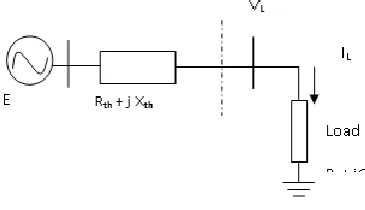
[image:3.595.313.550.111.208.2]Network equivalent at a bus is a straightforward practice for estimation of voltage stability of an intricate system in global mode. Due to ease of determining equivalents, it is most viable way for stability analysis and control power systems in real time. In majority of the cases, network equivalent had been obtained by using Thevenin’s theory. In Fig. 3 left part shows Thevenin’s equivalent of power grid excluding the bus to be monitored.
Fig. 3. Thevenin’s equivalent model
The two possible solutions of load bus voltage can be determined by solving Equation (5).
0
)
P
P
)(
X
(R
V
E
-V
)
Q
X
P
R
2(
V
2L 2 L 2 th 2 th 2 L 2 L L th L th 4
L
2
(5) As the load increases, two solutions of VL move towards each other and merge together at the threshold of VI/VC. Therefore, equating discriminant of equation (5) to zero becomes the criterion for detecting the voltage stability margins. In some cases, closeness of load impedance to Thevenin’s impedance had been used as proximity indicator.
D. Power Transfer limit of a Line
Most of the line indices have been obtained from the limitation on power transfer through a line. The maximum power limit reaches when no real solution exists for the receiving end voltage.
Fig. 4. Single line diagram of a transmission line The following expression for receiving end voltage of the line shown in Fig. 4 can be obtained by simplifying the expressions for receiving end active and reactive powers. 𝑉𝑟4+ 2 𝑅𝑃𝑟+ 𝑋𝑄𝑟 𝑉𝑟2− 𝑉𝑠2𝑉𝑟2+ 𝑅2+ 𝑋2 𝑃𝑟2+ 𝑄𝑟2 = 0 (6)
Therefore, equating the expression for the discriminant of equation (6) to zero becomes the criterion for deriving the critical limits of various line VSIs.
Where:
Vs∠𝛿𝑠: Sending end bus voltage
𝑆𝑠(𝑃𝑠+ 𝑗𝑄𝑆): Sending end power
Vr, ∠𝛿𝑟: Receiving end bus voltage
𝑆𝑟(𝑃𝑟+ 𝑗𝑄𝑟): Receiving end power
R, X, Y: line Resistance, reactance and shunt admittance respectively.
[image:3.595.66.273.121.366.2]Some indices in terms of ABCD parameters have also been derived from the pie model of transmission line as shown in the Fig. 5[49, 52].
Fig. 5. Transmission line model with shunt admittance E. Reactive power consumptions of lines
An overloaded line consumes high reactive power and consequently restricts transfer of reactive power to receiving end connected loads. Near the point of VC, enhancing the apparent power from the sending end of the line no longer yields an addition to the apparent power delivered to loads. Therefore, increase in reactive power losses is the indicator of voltage instability [25, 28]. F. Lyapunov stability theory
Lyapunov stability theory had been initially established for direct stability investigation of power systems. Hence a technique based on it had been effectively applied and implemented as a voltage stability predictor in [62]. This scalar function had been shown to directly related with the area encircled by the Q- ln V curve or P- curve assuming PQ loads and thus a measure of
VI/VC [63].
Vrδr
Receivi ng end Bus Sending
end Bus
Pr, Qr R + jX
Ps, Qs
Vsδs
I
Vjδj
Bus j Bus i
Pj,Qj R + jX
Pi,Qi Viδi
[image:3.595.308.552.468.548.2] [image:3.595.74.257.506.611.2]Voltage Stability Indices: Formulation and Classification Perspectives
A difficulty with this index is that it cannot be readily modified to include more complex system models.
Therefore, in literature using any of the following conditions and simplifying Equations (5)-(6), the indices to predict the voltage stability condition, are derived:
1. Load flow Jacobian matrix
2. Load flow solutions (System variables and parameters) 3. Maximum power transfer theorem
4. Power transfer limit of a Line
5. Feasible voltage solutions of the load buses
6. Reactive power consumption of the line 7. Lyapunov stability theory
III. CLASSIFICATION OF VOLTAGE STABILITY INDICES
A.
Based on Criterion/Method used [image:4.595.58.551.194.383.2]Classification of indices based on formulation and calculation methods is shown
in the Fig.6.
Fig. 6. Classification of Indices based on the criterion/method of calculation
B.
Based on Power System Parameters and Variables Power system variables can be obtained from either load flow solutions or the measurements of voltages, currents and powers injected of various buses. VSIs calculated from these system variable and parameters distinguish the weak parts of power system for initiating the corrective action against VI/VC.Therefore, from the identification of the part prone to VI/VC, these are classified as:
1. Bus Indices 2. Line Indices 3. Overall Indices
Bus Indices can identify the buses nearest to voltage stability limits and thus the suitable candidate buses for installation of shunt FACTs controllers. Similarly line indices have been utilized for providing series compensation in weak lines. The overall indices anticipate the stability state of the whole power system instead of indicating weak buses or lines.
An inclusive survey has been done and the imperative indices developed so far are reported in the chronological order along with the criterion used for their formulation and presented in section IV.
C.
Based on MeasurementsWith the inception of phasor technology with Phasor Measurement Unit (PMU) and advanced communication technologies, time tagged phasors can be obtained. Analog voltages and currents are converted into phasors and these time tagged phasors are delivered to phasor data concentrators via advanced communication modes with
minimum delay. These phasors are converted into useful information predicting the state of power system at the monitoring and control centres. Therefore, many indices had been derived with phasor information for early anticipation of power system instability.
Voltage stability surveillance and controls based on measurement can be classified as follows:
1. Local Measurements [22, 24-29] 2. Wide Area Monitoring [33, 55, 58-61]
Network equivalent at a critical/monitoring bus may be determined from voltage and current phasors measurements with PMUs installed at these buses. Theses buses are analysed independently as no synchronization and information of other buses (Voltages/currents) is required.
The dynamic and wide area tracking of the power system state is quite obvious with the phasor measurement units placed at optimal locations for complete observability.
IV. BUS,LINE AND OVERALL VOLTAGE STABILITY INDICES
A. Bus Indices: Bus indices that predict the vulnerable buses are tabulated in Table II.
Classification
of Indices
Jacobian matrix Based
Determinanat of J
Minimum Eigen/ Singular
Maximum inverse Eigen/
Singular Sensitivity
Factors
PV /QV Curves
Using Continuation
Power Flow
System Variables and Parameters
Based
Using Load
flow solutions MeasurementsUsing
Local Measurements
Wide Area Measurements
Lyapunov stability theory
Table- II: Bus Indices
Index
Expression
Stability
Condition
Concept
Used
Author
Reference1. L-Index
𝐿𝑗 = 1 −
𝐹𝑗𝑖𝑉𝑖
𝑉𝑗 𝑖∈𝛼𝑔
𝐿𝑗 < 1 Kessel P et al,
1986 [21]
2. Voltage Index Predictor
∆𝑆 = 𝑉𝑗− 𝑍𝑡𝐼𝑖𝑗
2
4𝑍𝑡
∆𝑆 > 0 Maximum
power transfer theorem
Julian D. E. et al,
2000 [22]
3. P-Q Boundary
𝑃𝑐𝑟 = −
𝐸2𝑅 𝑡
2𝑋𝑡2 +
𝑍𝑡 𝐸
2𝑋𝑡2
𝑄𝑐𝑟= 𝑃𝐿𝑋𝑡
𝑅𝑡 − 𝐸2 2𝑅𝑡2 +
𝑍𝑡 𝐸 𝐸2−4𝑃𝐿𝑅𝑡 2𝑅𝑡2
𝑃𝐿< 𝑃𝑐𝑟
𝑄𝐿< 𝑄𝑐𝑟
Feasible solution of voltage equations
Haque M. H.,
2003 [23]
4.Voltage Collapse Prediction Index
𝑉𝐶𝑃𝐼𝑘 = 1 − 𝑉𝑚′ 𝑛
𝑚 =1 𝑚 ≠𝑗
𝑉𝑘
𝑉𝐶𝑃𝐼𝑘 < 1 Feasible
solution of power flow and voltage equations
Balamourougan V. et al, 2004
[24]
5.S Difference
Criterion 𝑆𝐷𝐶 = 1 +
∆𝑉𝑟𝐼𝑟∗
𝑉𝑟∆𝐼𝑟∗
𝑆𝐷𝐶 > 0 Increase in reactive power losses of the line
Verbic G. et al.,
2004 [25]
6.Impedance
Stability Index 𝐼𝑆𝐼 =
𝑍𝐿− 𝑍𝑡
𝑍𝐿
𝐼𝑆𝐼 > 0 Maximum power transfer theorem
Smon I. et al.,
2006 [26]
Continued …
7.ZL/ZS ratio 𝑍𝐿 𝑍𝑆
= 𝑀 + 1
−𝑀 cos 𝛽 + 𝑀 cos 𝛽 2𝑀2+ 1 Where:
𝑀 = 𝑆2− 𝑆1 𝑌2+ 𝑌1 𝑆2+ 𝑆1 𝑌2− 𝑌1
𝑍𝐿 𝑍𝑆
> 1 Maximum power transfer theorem
Wiszniewski A., 2007
[27]
8.Voltage
Stability Index 𝑉𝑆𝐼𝑖 = 1 +
𝐼𝑖
𝑉𝑖
∆𝑉𝑖 ∆𝐼𝑖
𝛼
𝑉𝑆𝐼𝑖 > 0 Increase in
reactive power losses of the line
Haque M. H.,
2007 [28]
9.Equivalent Node Voltage Collapse Index
𝐸𝑁𝑉𝐶𝐼 = 2𝐸𝑘𝑉𝑛𝑐𝑜𝑠𝜃𝑘𝑛 − 𝐸𝑘2 𝐸𝑁𝑉𝐶𝐼 > 0 Voltage
quadratic equation solution
Wang Y., et al., 2009
[29]
10.Linearized motor voltage stability index
𝐿𝑀𝑉𝑆𝐼𝑖 =
𝑀𝑉𝑆𝐼𝑖 𝑑 𝑀𝑉𝑆𝐼𝑖
𝑑𝜆𝑖
Where:
𝑀𝑉𝑆𝐼𝑖 = 𝑑𝑒𝑡 𝐴𝑖
𝐿𝑀𝑉𝑆𝐼𝑖 > 0 Singularity of
the equivalent load state matrix with dynamic model of induction motor
Gu W. et al., 2010
Voltage Stability Indices: Formulation and Classification Perspectives
11.DSY (Derivative of the load apparent power with respect to its admittance)
𝐷𝑆𝑌 = Δ𝑆𝑙 𝑉𝑙2Δ𝑌𝑙
𝐷𝑆𝑌 > 0 Maximum power transfer theorem
Parniani M. et al., 2010
[31]
12.Voltage stability Risk indices
𝑉𝑆𝑅𝐼𝑗= 1 𝑁
𝑑𝑖+ 𝑑𝑖−1 Δ𝑡 𝑗
𝑖=𝑗 −𝑁+1 2
Where di is percentage diversity between voltage measurements
Most negative index, shows the highest risk of voltage instability
Transient variation of the system voltages
Seethalekshmi K. et al., 2010
[32]
13.Simplified Voltage Stability Index
𝑆𝑉𝑆𝐼𝑖 =
Δ𝑉𝑖
𝛽𝑉𝑖
𝑆𝑉𝑆𝐼𝑖 < 1 Maximum
power transfer theorem
Pérez-Londoño S. et al., 2014
[33]
14.Linear M-
index 𝑀𝑖 = 1 − 𝑉𝑖 𝐸𝑒𝑓𝑓𝑖− 𝑉𝑖 𝑉𝑐𝑟𝑖
2
𝑀𝑖 > 0 Voltage
quadratic equation solution
Matavalam A.R.R. et al, 2015
[34]
15.dV dQ index 𝕀𝑖 ≜ 𝑄𝑗𝛿𝑉𝑖 𝑉𝑖𝛿𝑄𝑗
𝑗𝜖 ℒ , 𝑖 ∈ ℒ 𝕀VC 𝑖→ +∞ at Singularity of J Simpson-Porco J.
W. et al, 2016
[35]
16. 𝑑𝑉𝐿 𝑑𝑉
𝐺
index
𝕁𝑖 ≜ 𝛿𝑉𝑖 𝛿𝑉𝑘
𝑘𝜖𝒢 , 𝑖 ∈ ℒ 𝕁𝑖→ +∞ at
VC
Singularity of J Simpson-Porco J. W. et al, 2016
[35]
17. dQG dQ
L
index
𝕂𝑖 ≜ 𝛿𝑄𝑘 𝛿 𝑄𝑖
𝑘𝜖𝒢 , 𝑖 ∈ ℒ 𝕂𝑖→ −∞ at
VC
Singularity of J Simpson-Porco J. W. et al, 2016
[35]
18. P-index
𝑃 − 𝑖𝑛𝑑𝑒𝑥𝑗= −2𝑃𝐿𝑗
𝑉𝑗 𝑑𝑉𝑗 𝑑𝑃𝐿𝑗
1 − −2𝑃𝐿𝑗
𝑉𝑗 𝑑𝑉𝑗 𝑑𝑃𝐿𝑗
𝑃 − 𝑖𝑛𝑑𝑒𝑥 < 1 Load flow Jacobian matrix
Kamel M. M. et al,
2017
[36]
B. Line Indices: Table III shows the imperative line
indices.
Table- III: Line Indices
Index
Expression
Stability
Condition
Concept Used
Author
Reference1. Line Stability
Factor 𝐿𝑄𝑃 = 4
𝑋 𝑉𝑠2
𝑄𝑟+
𝑃𝑠2𝑋
𝑉𝑠2
𝐿𝑄𝑃 < 1 Power limit of a line transfer Mohamed A. et al, 1989 [37]
2. Voltage Stability Load Index
𝑉𝐿𝑆𝐼 =
4 𝑉𝑠𝑉𝑟𝑐𝑜𝑠𝛿 −𝑉𝑟2𝑐𝑜𝑠𝛿𝑉𝑠2
𝑉𝐿𝑆𝐼 < 1
Power transfer
limit of a line Rahman TKA et al., 1995
[38]
3. Transmission Path Stability Index
TPSI = 0.5Vg - ΔV
d
𝑇𝑃𝑆𝐼 > 0 Maximum powertransfer theorem
Gubina F. et al,
1995 [39]
4. Line Stability
Index
) sin(
4
2
V i Q X
Lm n j
𝐿𝑚𝑛 < 1 Power transfer
limit of a line
Moghavemmi M.
5. Line Stability
Index 𝐿𝑃 =
4𝑅𝑃𝑗
𝑉𝑖𝑐𝑜𝑠 𝜃 − 𝛿 2
𝐿𝑝< 1 Power transfer
limit of a line
Moghavemmi M.
et al, 2001 [41] 6. Fast Voltage
Stability Index X
4 =
V Q Z
FVSI 2
i j
2 𝐹𝑉𝑆𝐼 < 1 Power transfer
limit of a line
Musirin I. et al,
2002 [42]
7. Lsr Index
𝐿
𝑠𝑟=
𝑆
𝑟𝑆
𝑟(𝑚𝑎𝑥 )𝐿
𝑠𝑟< 1
Power transfer limit of a line
Albuquerque MA et al, 2003
[43]
8. Voltages stability Load Bus Index
𝑉𝐿𝑆𝐵𝐼 = 𝑉𝑟 ∆𝑉
𝑉𝐿𝑆𝐵𝐼 > 1 Power transfer limit of a line
Milosevic B. et al., 2003
[44]
9. Voltage Stability Margin Index
𝑉𝑆𝑀𝐼 =𝛿𝑚𝑎𝑥 − 𝛿 𝛿𝑚𝑎𝑥
𝑉𝑆𝑀𝐼 > 0 Maximum power transferable through a line
He T. et al., 2004
[45]
10.Power Transfer
Stabilty Index
𝑃𝑇𝑆𝐼 =
2𝑆𝑟𝑍 1+𝑐𝑜𝑠 𝜃−𝛿 𝑉𝑠2
𝑃𝑇𝑆𝐼 < 1 Maximum power transferable through a line
Nizam M. et al, 2006
[46]
11.New Line
Stability Index 𝑁𝐿𝑆𝐼 =
𝑃𝑟𝑅 + 𝑄𝑟𝑋
𝑉𝑠2/4
𝑁𝐿𝑆𝐼 < 1 Maximum power transferable through a line
Yazdanpanah- Goharrizi A. et al, 2007
[47]
12. Line Stability
Index 𝐿𝑖𝑗 =
4𝑍2𝑄 𝑟𝑋
𝑉𝑠2 𝑅𝑠𝑖𝑛𝛿 − 𝑋𝑐𝑜𝑠𝛿 2
𝐿𝑖𝑗 < 1 Maximum power
transferable through a line
Subramani C. et al, 2009
[48]
13.Line collapse Proximity Index
𝐿𝐶𝑃𝐼
=4𝐴𝑐𝑜𝑠𝛼 𝑃𝑗𝐵𝑐𝑜𝑠𝛽 + 𝑄𝑗𝐵𝑠𝑖𝑛𝛽 𝑉𝑖𝑐𝑜𝑠𝛿 2
𝐿𝐶𝑃𝐼 < 1 Voltage quadratic equation solution
Tiwari R. et al., 2012
[49]
14. New Voltage
stability Index 𝑁𝑉𝑆𝐼 =2𝑍𝑋 𝑃𝑟
2+ 𝑄 𝑟2
2𝑄𝑠𝑋 − 𝑉𝑠2
𝑁𝑉𝑆𝐼 < 1 Maximum power transferable through a line
Kanimozhi R. et al, 2013
[50]
Continued …
15.Critical Boundary Index
𝐶𝐵𝐼𝑖𝑘 = ∆𝑃𝑖𝑘2 + ∆𝑄𝑖𝑘2
𝐶𝐵𝐼𝑖𝑘 > 0 Voltage
quadratic equation solution
Furukakoi, M. et al., 2018
[51] 16.Line Voltages
stability Index 𝐿𝑉𝑆𝐼𝑗 =
2𝑉𝑅𝑗𝐴𝑗𝑐𝑜𝑠 𝛽𝑗− 𝛼𝑗
𝑉𝑆𝑗𝑐𝑜𝑠 𝛽𝑗− 𝛿𝑆𝑅𝑗
𝐿𝑉𝑆𝐼 < 1 Maximum power transferable through a line
Ratra R. et al., 2018
[52]
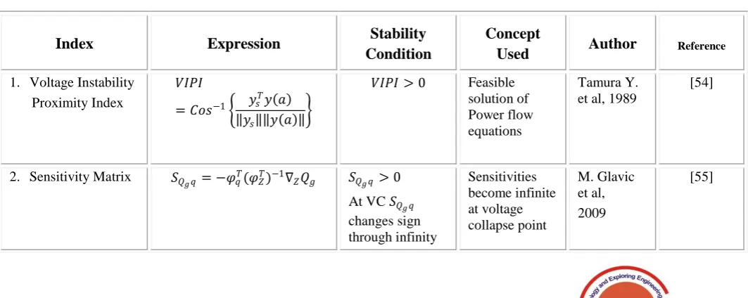
C. Overall Indices:
Overall indices are generally Jacobian based and well analyzed in [53]. Overall indices give the measure of the
[image:7.595.40.572.575.787.2]proximity to VC taking into account the whole power system model. Some of these are enumerated in the table IV.
Table IV: Overall Indices
Index
Expression
Stability
Condition
Concept
Used
Author
Reference 1. Voltage InstabilityProximity Index
𝑉𝐼𝑃𝐼
= 𝐶𝑜𝑠−1 𝑦𝑠 𝑇𝑦 𝑎
𝑦𝑠 𝑦 𝑎
𝑉𝐼𝑃𝐼 > 0 Feasible solution of Power flow equations
Tamura Y. et al, 1989
[54]
2. Sensitivity Matrix 𝑆𝑄𝑔𝑞 = −𝜑𝑞𝑇(𝜑𝑍𝑇)−1∇𝑍𝑄𝑔 𝑆𝑄𝑔𝑞> 0 At VC 𝑆𝑄𝑔𝑞 changes sign through infinity
Sensitivities become infinite at voltage collapse point
M. Glavic et al, 2009
Voltage Stability Indices: Formulation and Classification Perspectives
3. Area of Voltage
Stability Region 𝐴𝑉𝑆𝑅 = 𝑄 𝑃 − 𝑄𝑙 𝑑𝑃 𝑃𝑛
𝑃𝑙
𝐴𝑉𝑆𝑅 > 0
Feasible solution ofPower flow equations
Lee C. Y. et al, 2010
[56]
4. Network sensitivity approach
𝑆𝐺𝑝 =
𝑃𝑔𝑡
𝑃𝑑𝑡
𝑆𝐺𝑞=
𝑃𝑔𝑡
𝑄𝑑𝑡
𝑆𝐺𝑝 → ∞ at VC
𝑆𝐺𝑞 → ∞ at VC
P-V curve
Althowibi et al., 2012
[57]
5. Voltage Instability Monitoring Index
𝑉𝐼𝑀𝐼𝑘
= 𝑊1 𝑘
𝐷𝐹𝑅𝑘
𝐷𝐹𝑅𝑚𝑎𝑥
+ 𝑊2 𝑘
𝐶𝑉𝐷𝑘
𝐶𝑉𝐷𝑚𝑎𝑥
𝑉𝐼𝑀𝐼𝑘< 1
Voltage Deviation and consecutive voltage deviation
Sodhi R. et
al, 2012 [58]
V. CONCLUSIONS
The earlier indices are mainly derived from the conditions of singularity of Jacobian obtained in Newton-Raphson method of load flow analysis. These indices are suitable in offline applications like planning and designing of power grids. The disadvantages of Jacobian based indices are high computational effort and accurate prediction is possible only when extremely close to instability point. Sensitivity factors are well recognized indices and implemented in several utilities all over the world. Sensitivity factors that show the variation of generated reactive powers with the changes in loading parameters involves simple calculations in off-line studies. Loading margin is the bench mark index of voltage collapse. But it requires more computation effort at far away point from the current state.
System variables and parameters based indices have been derived from the concept of maximum power transfer theorem and maximum power flow through a line. These indices can be evaluated using load flow solutions or measurements. Measurement based indices can be determined either using local measurements or global measurements. Thevenin’s equivalent model is obtained and utilised for calculation of local measurement based indices. Although the approach is simple and computationally less expensive, time window frame size poses inaccuracy in Thevenin’s equivalent estimation and hence difficulties in actual implementations.
The comprehensive survey concludes that some indices are more suitable for real time control as these can be calculated easily in spite of less accuracy. On the other hand, some indices involve higher computational costs with more accuracy and hence more suitable for offline studies. All the aforesaid indices have their advantages and limitations. Therefore, to acclaim a specific index is not practical as it depends on the application and viability.
REFERENCES
1. G. Andersson, P. Donalek, R. Farmer, N. Hatziargyriou, I. Kamwa, P. Kundur, “Causes of the 2003 major grid blackouts in North America and Europe, and recommended means to improve system dynamic performance”, IEEE Transactions on Power System, vol. 20, no.4, pp. 1922-1928, November 2005.
2. C. W. Taylor, Power System Voltage Stability and Control, New York: McGraw-Hill, 1994.
3. W. Lu, Y. Bésanger, E. Zamaï and D. Radu, “Blackouts: Description, Analysis and Classification”, Proceedings of the 6th
WSEAS International Conference on Power Systems, Lisbon, Portugal, September 22-24, pp. 429-434, 2006.
4. “India’s Mass Power Failure Worst ever in World History”, Outlook, Press trust of India, July 31, 2012.
5. P. Kundur, Power System Stability and Control , New York : McGraw-Hill, 1994.
6. T. V. Cutsem, and C. Vournas, Voltage Stability of Electric Power Systems, Norwell, MA : Kluwer, 1998
7. A.K Panchal , “Voltage Stability of a Large Grid”, Proc. of 7th International Power Engg Conference , pp 1 - 550, Nov. 29 -Dec. 2 2005.
8. V. A. Venikov, V. A. Stroev, V. I. Idelchik, and V. I. Tarasov, “Estimation of electrical power system steady state stability in load flow calculations”, IEEE Trans. on Power Apparatus and Systems, vol. 94, no. 3, pp. 1034-1041, May/June 1975.
9. P. A. Lof, T. Smecl, G. Anderson, and D. J. Hill, “Fast calculation of a voltage stability index,” IEEE Trans. on Power Systems, vol. 7, pp. 54-64, Feb. 1992.
10. B. Gao, G.K. Morison and P. Kundur, "Voltage Stability Evaluation Using Modal Analysis", IEEE Trans. on Power Systems, Vol. 7, No. 4, pp. 1529- 1542, November 1992.
11. H. D. Chiang and R. J. Jumeau, “Toward a practical performance index for predicting voltage collapse in electric power systems", IEEE Trans. Power Systems, vol. 10, no. 2, pp. 584-592, May 1995. 12. R. Seydel, Practical Bifurcation and Stability Analysis - From Equilibrium to Chaos, New York: Springer- Verlag, second edition, 1994.
13. O. O. Obadina, and G. J. Berg, “Identifying electrically weak and strong segments of power system from a voltage stability view point”, IEE Proc., vol. 137, no. 3, pp. 205-212, May 1990. 14. N. Flatabo, R. Ognedal, and T. Carlsen,“Voltage stability condition
in a power transmission system calculated by sensitivity methods”, IEEE Trans. on Power Systems, vol. 5, no. 4, pp. 1286-1293, November 1990.
15. A. Berizzi, P. Finazzi, D. Dosi, P. Marannino, and S. Corsi, “First and second order methods for voltage collapse assessment and security enhancement”, IEEE Trans. on Power Systems, vol. 13, no. 2, pp. 543 – 551, May 1998.
16. L. Wang and A. A. Girgis, “On-line detection of power system small disturbance voltage instability”, IEEE Trans. on Power Systems, vol. 11, no. 3, pp. 1304-1313, August 1996.
17. A. C. Z. de Souza, C. A. Ca~nizares, and V. H. Quintana, \Critical bus and point of collapse determination using tangent vectors," Proc. NAPS, M.I.T., pp. 329-333, November 1996.
18. M. Suzuki, S.Wada, M. Sato, T. Asano, and Y. Kudo, “Newly developed voltage security monitoring system," IEEE Trans. Power Systems, vol. 7, no. 3, pp. 965-973, August 1992.
19. A. Venkataramana, C. Colin, “The continuation power flow a tool for steady state voltage stability analysis”, IEEE Trans. on Power Syst vol. 7(1), February 1992.
20. N. Yorino, S. Harada and H. Cheng, “A Method to approximate a closest loadability limit using multiple load flow solutions”, IEEE Trans. on Power Systems , vol. 12, no. 1, pp. 424-429, February 1997.
22. D. E. Julian, R. P. Schultz, K. T. Vu, W. H. Quaintance, N. B. Bhatt, and D. Novosal,“Quantifying proximity to voltage collapse using the voltage instability predictor (VIP)”, IEEE Power Eng. Soc., vol. 2, pp. 931-936, July 2000.
23. M. H. Haque, “Novel method of assessing voltage stability of a power system using stability boundary in P-Q plane”, Electric Power Systems Research, vol. 64, pp. 35-40, 2003
24. V. Balamourougan, T.S. Sidhu and M.S. Sachdev, “Technique for online prediction of voltage collapse”, IEE Proceedings-Generation, Transmission and Distribution, vol. 151, no. 4, pp. 453-460, July 2004.
25. Verbic G.,Gubina F., “A new concept of voltage-collapse protection based on local phasors”,IEEE Trans on Power Delivery, vol. 19, no. 2, pp. 576–81. April 2004.
26. I. Smon, G. Verbic, F. Gubina, Local voltage-stability index using Tellegen’s theorem, IEEE Trans. on Power Systems, vol. 21, no. 3, pp. 1267–1275, August 2006.
27. A. Wiszniewski, “New criteria of voltage stability margin for the purpose of load shedding”, IEEE Trans. Power System, vol. 22, pp. 1367-1371, July 2007.
28. M.H. Haque, Use of local information to determine the distance to voltage collapse. In Proceedings of the International Power Engineering Conference (IPEC 2007), Singapore, pp. 407–412, 3–6 December 2007.
29. Y. Wan, W. Li and J. Lu, “A New node voltage stability index based on local phasors”, Electric Power Systems Research, vol. 79, no. 1, pp. 265-271, January 2009.
30. W. Gu, Q.Wan, “ Linearized voltage stability index for wide-area voltage monitoring and control”, International Journal Of Electrical Power & Energy Systems, 32(4), 333-36, May 2010.
31. Parniani M, Vanouni M., “ A fast local index for online estimation of closeness to loadability limit”, IEEE Transactions on Power Systems, 25(1):584-85 February 2010.
32. K. Seethalekshmi, S.N. Singh, S.C. Srivastava, “Adaptive scheme for minimal load shedding utilizing synchrophasor measurements to ensure frequency and voltage stability”, Electric Power Components and Systems, 38(11):1211-27, August 2010.
33. S. Pérez-Londoño, L. F. Rodríguez, G. A Olivar, “Simplified voltage stability index (SVSI)”, International Journal of Electrical Power & Energy Systems, 63, 806-13, December 2014.
34. A. R. Matavalam, V. Ajjarapu “Calculating the long term voltage stability margin using a linear index”, In IEEE Power & Energy Society General Meeting, pp. 1-5, July 2015.
35. J. W. Simpson-Porco, F. Bullo., “Distributed monitoring of voltage collapse sensitivity indices”, IEEE Transactions on Smart Grid, 7(4), 1979-88, Juyl 2016.
36. M. M. Kamel, A. A. Karrar, A. H. Eltom, “Development and Application of a New Voltage Stability Index for On-Line Monitoring and Shedding”, IEEE Transactions on Power Systems, vol. 33, no. 2, July 2017.
37. A.Mohamed, G.B.Jasmon, S.Yusoff “A static voltage collapse indicator using Line stability factors”, Journal of Industrial Technology, vol. 7, No. 1, pp. 73-85, 1989.
38. T. A. Rahman, G. B. Jasmon, “A new technique for voltage stability analysis in a power system and improved loadflow algorithm for distribution network”, In IEEE International Conference Proceedings of Energy Management and Power Delivery, Vol. 2, pp. 714-719, November 1995.
39. F. Gubina, B. Strmcnik, “Voltage collapse proximity index determination using voltage phasors approach, IEEE Trans. on Power Systems, vol. 10, no. 2, pp. 788 - 794. May 1995.
40. M. Moghavvemi, and F. M. Omar, “Technique for contingency monitoring and voltage collapse prediction”, IEE Proceedings- 41. Generation Transmission and Distribution, vol. 145, no. 6, pp.
634-640, November 1998.
42. M. Moghavvemi, M. O. Faruque, “Technique for assessment of voltage stability in illconditioned radial distribution network”, IEEE Power Engineering Review, 21(1), pp. 58-60, Jan 2001.
43. I. Musirin, and T. K. A. Rahman, “Novel fast voltage stability index (FVSI) for voltage stability analysis in power systems”, Student Conf. in Research and Development Proc., Malaysia, pp. 265 – 268, July 2002
44. MA Albuquerque, CA Castro, “A contingency ranking method for voltage stability in real time operation of power systems”, In IEEE Power Tech Conference Proceedings, Vol. 1, June 2003.
45. B. Milosevic, M. Begovic, “ Voltage Stability Protection and control using wide- area network of phasor measurements”, IEEE Trans. on Power Systems, vol. 18, no. 1, pp. 121 – 127, February 2003. 46. T. He, S. Kolluri, S. Mandal, F. Galvan, P. Rasigoufard,
“Identification of weak locations in bulk transmission systems using
voltage stability margin index”, In IEEE Power Engineering Society General Meeting, pp. 1814-1819, June 2004.
47. M. Nizam, A. Mohamed, A. Hussain, “Dynamic voltage collapse prediction in power systems using power transfer stability index”, In IEEE International Power and Energy Conference, pp. 246-250, Nov 2006.
48. A. Yazdanpanah-Goharrizi, R. Asghari, “A novel line stability index (NLSI) for voltage stability assessment of power systems”, In 7th WSEAS International Conference on Power Systems, Beijing, China, pp. 164-167, Sep 2007.
49. C. Subramani, S. Dash, M. A. Bhaskar, M Jagadeeshkumar, K. Sureshkumar, R. Parthipan, “Line outage contingency screening and ranking for voltage stability assessment”, In IEEE International Conference on Power Systems, pp. 1-5, DEC 2009.
50. R. Tiwari, K. R. Niazi, and V. Gupta, “Line collapse proximity index for prediction of voltage collapse in power systems”, IJEPES, vol. 41, no. 1, pp. 105-111, 2012.
51. R. Kanimozhi, K. Selvi, “A novel line stability index for voltage stability analysis and contingency ranking in power system using fuzzy based load flow”, Journal of Electrical Engineering & Technology (JEET), 8(4), pp. 694-703, July 2013.
52. M. Furukakoi, O.B. Adewuyi, M.S.S Danish, A.M Howlader, T. Senjyu, T. Funabashi, “Critical Boundary Index (CBI) based on active and reactive power deviations”, International Journal of Electrical Power & Energy Systems, 100, pp. 50-57, February 2018. 53. S. Ratra, R. Tiwari, K. R. Niazi, “Voltage stability assessment in power systems using line voltage stability index”. Computer and Electrical Engg., pp. 1–13, January 2018.
54. Canizares CA. Voltage stability assessment: concepts, practices and tools. IEEE PES Power System Stability Subcommittee Special Publication; 2002.
55. Y. Tamura, K. Sakamoto, Y.Tayama, “Current issues in the analysis of voltage instability phenomena”, In Bulk power system voltage phenomena voltage stability and security, p.5-39–53, 1989. 56. M. Glavic,.T.V. Cutsem, “Wide-area detection of voltage instability
from synchronized measurements. Part 1: Principle”, IEEE Trans. Power Syst., 24(3), pp. 1408–1416, 2009.
57. C. Y. Lee, S. H. Tsai, and Y. K. Wu, “A new approach to the assessment of steady-state voltage stability margins using the P–Q–V curve”, Electrical Power and Energy Systems vol. 32, no. 10, pp. 1091–1098, December 2010.
58. F. A. Althowibi, M.W. Mustafa, “Power system network sensitivity to voltage collapse”, in Proceedings of the international power engineering and optimization conference, pp. 379–83, 2012. 59. R. Sodhi, S C Srivastava and S N Singh, "A simple scheme for wide
area detection of impending voltage instability”, IEEE Transactions on Smart Grid, Vol. 3, No. 2, June 2012.
60. L. Mili, T. Baldwin, and R. Adapa, “Phasor measurement placement for voltage stability analysis of power systems”, Proc. IEEE 29th Conf. on
61. Decision and Control, Honolulu, pp. 3033-3038, 1990.
62. B. Genet, J. C. Maun, “Voltage-stability monitoring using wide area measurement systems”, Power Tech., Lausanne, pp. 1712-1717, July 1-5, 2007.
63. S. Corsi, “Wide area voltage regulation & protection”, Proc. IEEE Power Tech. Conf., Bucharest, pp. 1-7, June 28-July 2, 2009. 64. T.J. Overbye, and C.L. DeMarco, “Improved techniques for power
system voltage stability assessment using energy methods,” Power Systems, IEEE Transactions on , vol.6, no.4, pp.1446-1452, November 1991.
65. T. J. Overbye, I. Dobson, and C. L. DeMarco, “Q-V curve interpretations of energy measures for voltage security", IEEE Trans. on Power Systems, vol. 9, no. 1, pp. 331-340, February 1994
AUTHORS PROFILE