International Journal of Innovative Technology and Exploring Engineering (IJITEE) ISSN: 2278-3075, Volume-8, Issue- 9S2, July 2019
Abstract— . A numerical method is used to observe the effect of microjets control on wall pressure spreading in sudden expansion two-dimensional planar duct. In order to find the microjet effectiveness 2-jets of 1 mm diameter orifice located precisely at 900 of intervals along a pitch-circle-distance (PCD) of 1.3 times the exit diameter of the nozzle in the base were employed to control actively. At the present study, the Mach number was used to calibrate the entry to duct was 2.2, and the area ratio of 2.56. The focus in this study and investigate the influence of length-to-diameter ratio (L/D) of a suddenly expanded duct and its effect on the development of the flow field. Hence, to achieve this, the duct length has been varied from 2 to 10. Nozzles are producing such Mach numbers the experiments were performed operating at nozzle pressure ratio (NPR) 3, 5, 7, 9, and 11. The convergent-divergent nozzle geometry has been studied using the K-ε standard wall function turbulence model and independently check with the ANSYS software.
Keywords— Nozzle, Area ratio, Nozzle pressure ratio, Microjet, Flow Control, ANSYS simulation, CFD.
INTRODUCTION
Design of the nozzle, which is a flow accelerating device is vital in the design stage of any aerospace vehicle. Designers need to take special care when they are designing a converging-diverging nozzle to achieve high-speed flow. It is well known that if the flow does not choke at the minimum diameter of the nozzle then in the diverging part of the nozzle the flow will decelerate rather than accelerate. Due to this, the mission will fail. Another critical concern at these high Mach number is the flow separation at the base of the fuselage, which will result in a considerable amount of drag. The base drag may be as high as seventy percent of the net drag at transonic Mach numbers during the jet off conditions.
In the early years of 2000, the researchers were interested in controlling the high-speed flows from the nozzle . During the late nineteenth century, during the year 1961, the authors investigated the base flows at supersonic speeds [1]. Later, Khan and Radhakrishnan [2]–[8] focused on sudden expansion flow control, and they experimentally investigated the flow through the convergent-divergent (CD) nozzle with sudden expansion duct in order to accomplish the base pressure control. To investigate and record the
Revised Manuscript Received on July 18, 2019.
Mohammad Nishat Akhtar, School of Aerospace Engineering, Universiti Sains Malaysia14300 Nibong Tebal, Penang, Malaysia. (E-mail: [email protected])
Elmi Abu Bakar, School of Aerospace Engineering, Universiti Sains Malaysia14300 Nibong Tebal, Penang, Malaysia. (E-mail: [email protected])
Abdul Aabid, Department of Mechanical Engineering, Faculty of Engineering, IIUM, 53100, Kuala Lumpur, Malaysia. (E-mail: [email protected])
Sher Afghan Khan, Department of Mechanical Engineering, Faculty of Engineering, IIUM, 53100, Kuala Lumpur, Malaysia. (E-mail: [email protected])
distribution of wall pressure as well as the nature of the flow field in the suddenly expanded duct and to control the base pressure, they used the tiny jets in the form of the orifice of 1 mm diameter as the microjets. Moreover, the authors also investigated the parametric effects on the control of base pressure such as area ratio, length to diameter ratio for different Mach numbers (ranging from 1.87 to 2.58) and nozzle pressure ratio (in the range from 3 to 11). The investigation of the base pressure control continued by varying the Mach number and area ratio at a different level of expansion to get the results of base pressure at supersonic flows from C-D nozzle [9]–[17].
Next, the researchers focussed on the numerical simulation, and they found that the some of the authors have used finite element method to investigate the thrust on the CD nozzle [18] and also the analysis of jet flow at Mach number 1.74 [19]. The De Level nozzle was designed and simulated in order to control the shock expansion to induce the flow separation using computational fluid dynamics (CFD) method [20]. In Ref. [21], they designed the three-dimensional CD nozzle to analysis the flow using CFD method. The authors [22] validate the experimental results using CFD method to study the effectiveness of the use of a passive control at the exit of the nozzle.
However, most of the study has been found to be for the non-similar cases of experimental. From 2017, the study has been switched to account for the influence of microjets in a duct with the CD nozzle. The authors designed and modeled the two-dimensional (2D) axisymmetric nozzle based on the density effect to investigate the flow field in the duct and the control effectiveness [23]–[26]. Further, the study continued to model the flow and to investigate the thrust force generated for different area ratio [27], [28]. On the continues growth on a simulation study, it was found that the nozzle has been modeled using a 2D model based on pressure effect [29]–[34]. The authors simulated the results using the contours plots. In the numerical simulation, it is essential to select an appropriate turbulence model, and the literature shows that most of the work has been done using K-Ɛ and K-ω standard wall function turbulence model. Moreover, the same turbulence model has also been used to investigate the supersonic flow through a wedge [35], [36] and non-circular cylinder [37]. Moreover, the experimental investigation is also found for active and passive control of baseflow using cylinders [38]–[42].
Based on the above literature review on the experimental and numerical method, it seems no work has been done on the effect of length to diameter ratio, the Mach number, the
Numerical Simulations of a CD Nozzle and
the Influence of the Duct Length
area ratio, and the nozzle pressure ratio (NPR). Therefore, in this work, the nozzle is designed and modeled using the finite element method for the case of Mach number 2.2 and the area ratio of 2.56 at NPR 11. The K-ε standard wall function turbulence model has been used to simulate the results.
PROBLEM DEFINITION
[image:2.595.301.556.251.395.2]The present work has been accomplished through numerical simulations using CFD. Therefore, a simple 2D planar model has been designed using commercial software ANSYS. The geometry of the nozzle is based on the designed Mach number, and the properties are taken into consideration as a standard CFD model. The dimensions of the nozzle are; the inlet diameter (Di) and length of convergent (Lc) is 26.52 mm and 35 mm respectively, throat diameter (Dt) is 6.45 mm, and exit diameter (De) and length of divergent (Ld) is 10 mm and 16.88 mm respectively. Next, is the suddenly expanded duct diameter (D) of the circular duct which is 16 mm, and the diameter of microjet (Dm) control is 1 mm.
Figure 1: Sudden Expansion Nozzle FINITE ELEMENT METHOD
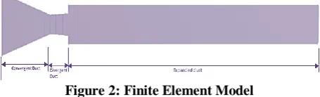
[image:2.595.69.271.321.392.2]Figure 2 shows the finite element model, which is designed through ANSYS geometry. From the figure, it has seen that the model has a different section that is convergent, throat, divergent, and expanded duct. In addition to that, the model also has a small microjet controller at the base region in order to control the flow in the base region.
Figure 2: Finite Element Model
It is essential to assign the boundary conditions (BC), which depends on the problem definition. Since the present model has been designed in 2D geometry, therefore, to map the BC’s a line (edge) has been selected. In this model, the BC’s have been assigned and named as the inlet, wall, and the outlet. The wall is divided into different section such as nozzle wall, base wall, and duct wall in order to see the variation of pressure and velocity in each zone.
Next, is the mesh is also crucial in the simulation of the flow. Therefore, the mesh in the present work has been used structured grid element shape, and the type is used ‘fine’
input values have been applied to the model is shown in table 1.
Figure 3: Mesh model
The simulation runs until the solution convergent with the reporting interval and profile interval of each iteration.
TABLE 1. Setup for solution initialization Solution Method
General-Solver Absolute, 2D planar, steady, Pressure-Based
Turbulence Model K-ε standard wall function Fluid Ideal gas, Viscosity by Sutherland
law
Solid Aluminum (default) Solution Method Second-order upwind Solution
Initialization
Standard from Inlet
Reference Value Inlet (Solid surface) RESULTS AND DISCUSSION
The primary purpose of this work is to optimize the flow-field at a different level of expansion (i.e., NPR) in the presence of a control mechanism in the form of microjet. The flow was simulated numerically at NPR 11 at Mach 2.2 for area ratio 2.56, to see the influence and the effects of the microjets on the base pressure, the Mach number, on the contours, and the results have been obtained.
Validation of Present Model
[image:2.595.55.283.523.592.2]For the validation of the present finite element, the model considered Khan et al., [2] experimental results, which is shown in figure 1. The case was found from the experimental data at Mach number 2.58 for area ratio of 3.24, NPR of 11 and L/D ratio of 6. The obtained base pressure values are dimensionless. The present results show a good agreement with the experimental work. Table 2 illustrates the comparison of results.
TABLE 2. Comparison of present results Base Pressure Khan et
al., [2]
Present Work
Percentage Error With control 0.0659 0.0671 1.78 Without Control 0.0445 0.0481 7.48 Pressure Effect
[image:2.595.299.554.641.694.2]International Journal of Innovative Technology and Exploring Engineering (IJITEE) ISSN: 2278-3075, Volume-8, Issue- 9S2, July 2019
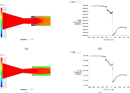
affected in each zone, such as convergent part, at the throat of the nozzle, in the divergent part of the nozzle, and in the enlarged duct. Therefore, in this section, the results considered from all zones of CD nozzle. The figures 4 to 8 illustrate the total pressure variation from the inlet to the outlet of the nozzle by considering contours and plots with and without control. In all the figures it shows blue color at the expanded duct immediately after the diverging part of the CD nozzle, which represents base pressure that suddenly ducts developing. From figure 4b and 4d, it has been observed that the microjet control the pressure value at the exit of the duct. For example, when the duct uncontrolled
the value of pressure is 2.25e5 pascals after controlling it reduces to 1.95e5. While for longer duct, the pressure increases after the deployment of the control, which is 3e5 pascals from uncontrol value of 2.1e5.
Moreover, when there is no flow control due to this, the pressure suddenly decreases and creating shocks at the exit of the divergent part of the nozzle. The base pressure becomes high; due to the presence of the oblique shocks waves. Therefore, to control this 1 mm diameter of micro-jets are used at the PCD of 1.3 at the exit diameter of the nozzle.
(a) (b)
[image:3.595.87.512.204.507.2](c) (d)
Figure 4: Pressure Distribution for L/D = 2 (a) and (b) Without Control of Micro-jets (c) and (d) With Control of Micro-jets
(c) (d)
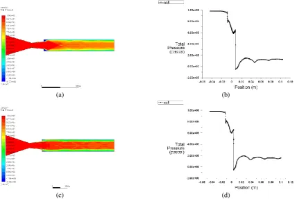
Figure 5: Pressure Distribution for L/D = 4 (a) and (b) Without Control of Micro-jets (c) and (d) With Control of Micro-jets
(a) (b)
(c) (d)
Figure 6: Pressure Distribution for L/D = 6 (a) and (b) Without Control of Micro-jets (c) and (d) With Control of Micro-jets
[image:4.595.87.516.231.518.2]International Journal of Innovative Technology and Exploring Engineering (IJITEE) ISSN: 2278-3075, Volume-8, Issue- 9S2, July 2019
[image:5.595.92.510.48.191.2](c) (d)
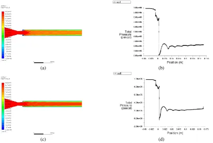
Figure 7: Pressure Distribution for L/D = 8 (a) and (b) Without Control of Micro-jets (c) and (d) With Control of Micro-jets
(a) (b)
(c) (d)
Figure 8: Pressure Distribution for L/D = 10 (a) and (b) Without Control of Micro-jets (c) and (d) With Control of Micro-jets
Mach number Variation
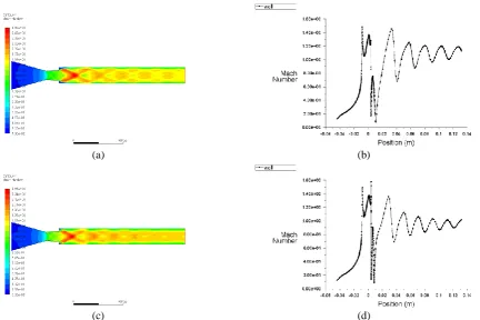
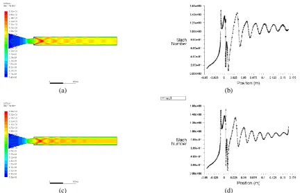
The variation of Mach number in the CD nozzle as well as in the duct is crucial. The figures 9 to 13 demonstrate the Mach number variation from the inlet to the outlet of the CD nozzle by considering contours and the Mach number plots with and without the micro-jets. Consequently, all plots show that the Mach number increases in the downstream of the duct.
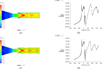
At L/D = 2 in the figure (9b) and (9d) the variation is almost similar and reaches close to each other which is 1.68 (without control) and 1.61 (with control) at the position of wall 0.04 m which is the exit location of the
[image:5.595.86.518.230.520.2](a) (b)
[image:6.595.87.512.48.353.2](c) (d)
Figure 9: Mach number Variation for L/D = 2 (a) and (b) Without Control of Micro-jets (c) and (d) With Control of Micro-jets
(a) (b)
(c) (d)
[image:6.595.88.514.396.680.2]International Journal of Innovative Technology and Exploring Engineering (IJITEE) ISSN: 2278-3075, Volume-8, Issue- 9S2, July 2019
(a) (b)
[image:7.595.89.511.46.335.2](c) (d)
Figure 11: Mach number Variation for L/D = 6 (a) and (b) Without Control of Micro-jets (c) and (d) With Control of Micro-jets
(a) (b)
(c) (d)
[image:7.595.85.518.373.661.2](a) (b)
[image:8.595.83.519.56.335.2](c) (d)
Figure 13: Mach number Variation for L/D = 10 (a) and (b) Without Control of Micro-jets (c) and (d) With Control of Micro-jets
CONCLUSIONS
The flow-field and wall pressure distribution in a convergent-divergent nozzle and in the duct was successfully studied using finite element method. The effect of microjets control in order to control the base pressure has been achieved. In view, the jets remained over expanded the base pressure without is high due to the presence of oblique shock waves. Under these circumstances, when the control is employed results in a marginal increase in the base. As the significant gain in the base, the pressure was achieved without control. The control does not influence adversely on the wall pressure flow field. The flow remained attached with the enlarged duct even at L/D = 2; this length seems to be the minimum length needed for the flow to remain attached.
ACKNOWLEDGMENT
The authors would like to acknowledge the Bridging Insentif Grant FASA 1/2019 (304.PAERO.6316572) and the RUI grant (RUI 1001/PAERO/8014035) provided by the Research Creativity and Management Office, Universiti Saint Malaysia to support this research.
REFERENCES
1. M. Badrinarayanan, J. R. Aeronaut. Soc., 65, 475–482,
(1961).
2. S. A. Khan and E. Rathakrishnan, Int. J. Turbo Jet Engines,
19, 119–126, (2002).
5. S. A. Khan and E. Rathakrishnan, Int. J. Turbo Jet Engines,
22, 163–183, (2005).
6. S. A. Khan and E. Rathakrishnan, Aircr. Eng. Aerosp.
Technol. An Int. J., 78, 293–309, (2006).
7. S. A. Khan and E. Rathakrishnan, Int. J. Turbo Jet Engines,
23, 233–258, (2006).
8. S. A. Khan and E. Rathakrishnan, J. Aerosp. Eng. Inst.
Eng. India, 87, 3–11, (2006).
9. M. A. A. Baig, F. Al-Mufadi, S. A. Khan, and E.
Rathakrishnan, Int. J. Turbo Jet Engines, 28, 59–69,
(2015).
10. S. Rehman and S. A. Khan, Aircr. Eng. Aerosp. Technol.,
80, 158–164, (2008).
11. M. A. A. Baig, F. Al-Mufadi, S. A. Khan, and E.
Rathakrishnan, Int. J. Turbo Jet Engines, 28, 59–69,
(2011).
12. M. Ahmed and A. L. I. Baig, Int. J. Eng. Sci. Technol., 4,
1892–1902, (2012).
13. S. A. Khan and E. Rathakrishnan, Int. J. Turbo Jet Engines,
21, 255–278, (2008).
14. S. Ashfaq, S. A. Khan, and E. Rathakrishnan, Int. Rev.
Mech. Eng., 8, 1–10, (2014).
15. Z. I. Chaudhary, V. B. Shinde, M. Bashir, and S. A. Khan,
Int. J. Energy, Environ. Econ., 24, 59–66, (2016).
16. M. A. A. Baig, S. A. Khan, C. Ahmed Saleel, and E.
Rathakrishnan, ARPN J. Eng. Appl. Sci., 7, 992–1002,
(2012).
17. F. A. G. M, M. A. Ullah, and S. A. Khan, ARPN J. Eng.
Appl. Sci., 11, 10041–10047, (2016).
18. A. Ali, A. Neely, J. Young, B. Blake, and J. Y. Lim,
“Numerical Simulation of Fluidic Modulation of Nozzle
Thrust,” in 17th Australasian Fluid Mechanics Conference,
2010, no. December, pp. 5–8.
19. K. M. Pandey and V. Kumar, Int. J. Chem. Eng. Appl., 1,
International Journal of Innovative Technology and Exploring Engineering (IJITEE) ISSN: 2278-3075, Volume-8, Issue- 9S2, July 2019
20. G. M. Kumar, D. X. Fernando, and R. M. Kumar, Adv.
Aerosp. Sci. Appl., 3, 119–124, (2013).
21. B.-A. Belega and T. D. Nguyen, “Analysis of Flow In
Convergent-Divergent Rocket Engine Nozzle Using
Computational Fluid Dynamics,” in International
Conference of Science Paper AFASES, 2015, p. 6.
22. O. Kostic, Z. Stefanovic, and I. Kostic, FME Trans., 43,
107–113, (2015).
23. K. A. Pathan, P. S. Dabeer, and S. A. Khan, “CFD
Analysis of Effect of Mach number, Area Ratio, and Nozzle Pressure Ratio on Velocity for Suddenly Expanded
Flows,” in 2nd International Conference for Convergence
in Technology (I2CT), 2017, pp. 1104–1110.
24. K. A. Pathan, “CFD Analysis of Effect of Area Ratio on
Suddenly Expanded Flows,” in 2nd International
Conference for Convergence in Technology (I2CT), 2017, pp. 1192–1198.
25. K. A. Pathan, P. S. Dabeer, and S. A. Khan, Int. Rev.
Aerosp. Eng., 11, 162–169, (2018).
26. K. A. Pathan, P. S. Dabeer, and S. A. Khan, J. Appl. Fluid
Mech., vol. 12, no. 4, pp. 1127–1135, (2019).
27. K. A. Pathan, P. S. Dabeer, and S. A. Khan, “CFD
Analysis of Effect of Flow and Geometry Parameters on
Thrust Force Created by Flow from Nozzle,” in 2nd
International Conference for Convergence in Technology (I2CT), 2017, pp. 1121–1125.
28. K. Ahmed, P. S. Dabeer, and S. Afghan, Case Stud. Therm.
Eng., 12, 696–700, (2018).
29. A. G. M. Fharukh, A. A. Alrobaian, A. Aabid, and S. A.
Khan, Int. J. Mech. Prod. Eng. Res. Dev., 8, 373–382,
(2018).
30. A. Khan, A. Aabid, and S. A. Khan, Int. J. Eng. Technol.,
7, 232–235, (2018).
31. S. A. Khan and A. Aabid, Int. J. Mech. Prod. Eng. Res.
Dev., 8, 1147–1158, (2018).
32. S. A. Khan, A. Aabid, and C. A. Saleel, Int. J. Mech.
Mechatronics Eng. IJMME-IJENS, 19, 70–82, (2019).
33. S. A. Khan, A. Aabid, F. A. G. M, A. A. Al-Robaian, and
A. S. Alsagri, CFD Lett., 11, 61–71, (2019).
34. A. Aabid, N. M. Mazlan, M. A. Ismail, N. Akhtar, and S.
A. Khan, Int. J. Eng. Adv. Technol., 8, 457–462, (2019).
35. S. A. Khan, A. Aabid, and A. S. C, Int. J. Mech.
Mechatronics Eng. IJMME-IJENS, 19, 170–177, (2019).
36. S. A. Khan, A. Aabid, I. Mokashi, A. A. Al-Robaian, and
A. S. Alsagri, CFD Lett., 11, 80–97, (2019).
37. M. F. M. Sajali, A. Aabid, S. A. Khan, F. A. G. M, and E.
Sulaeman, CFD Lett., 11, 37–49, (2019).
38. S. A. Khan, M. Asadullah, and J. Sadiq, Int. J. Mech.
Mechatronics Eng., 8, 69–74, (2018).
39. S. A. Khan and M. Asadullah, Int. J. Mech. Prod. Eng. Res.
Dev., 8, 39–44, (2018).
40. M. Asadullah, S. A. Khan, W. Asrar, and E. Sulaeman,
“Int. J. Mech. Eng. Robot. Res., 7, 428–432, (2018).
41. M. Asadullah, S. A. Khan, W. Asrar, and E. Sulaeman,
“Passive control of base pressure with the static cylinder at supersonic flow,” in IOP Publishing House, IOP Conf. Series: Materials Science and Engineering, 2018, pp. 1–10.
42. M. Asadullah, S. A. Khan, W. Asrar, and E. Sulaeman,