Received 27 Dec 2015|Accepted 10 May 2016|Published 10 Jun 2016
Plasma optical modulators for intense lasers
Lu-Le Yu
1,2, Yao Zhao
1,2, Lie-Jia Qian
1,2, Min Chen
1,2, Su-Ming Weng
1,2, Zheng-Ming Sheng
1,2,3,
D. A. Jaroszynski
3, W. B. Mori
4& Jie Zhang
1,2Optical modulators can have high modulation speed and broad bandwidth, while being compact. However, these optical modulators usually work for low-intensity light beams. Here we present an ultrafast, plasma-based optical modulator, which can directly modulate high-power lasers with intensity up to 1016W cm2to produce an extremely broad spectrum with a fractional bandwidth over 100%, extending to the mid-infrared regime in the low-frequency side. This concept relies on two co-propagating laser pulses in a sub-millimetre-scale underdense plasma, where a drive laser pulse first excites an electron plasma wave in its wake while a following carrier laser pulse is modulated by the plasma wave. The laser and plasma parameters suitable for the modulator to work are based on numerical simulations.
DOI: 10.1038/ncomms11893 OPEN
1Key Laboratory for Laser Plasmas (Ministry of Education), Department of Physics and Astronomy, Shanghai Jiao Tong University, Shanghai 200240, China. 2Collaborative Innovation Center of IFSA (CICIFSA), Shanghai Jiao Tong University, Shanghai 200240, China.3SUPA, Department of Physics, University of
O
ptical modulators are key components for manipulating optical signals, which are widely used in scientific and industrial applications. For example, high-speed compact electro-optic modulators (EOMs) are essential for data commu-nications1–4. EOMs can alter the fundamental characteristics (that is, amplitude, frequency, phase and polarization) of a light beam in a controllable manner, by making use of electro-optic effects to change the refractive index of a material when an external radio-frequency electric field driver is applied. Thanks to the rapid development of the field of radio-frequency photonics5,6 together with advanced material and microfabrication techno-logies3,4,7, the modulation speed of EOMs has dramatically increased from megahertz to 100 gigahertz (refs 8–10) over the past decade. However, it is still very challenging to successfully achieve terahertz (THz) speed for EOMs using current technologies due to the speed limitation of the high-voltage driver1. On the other hand, the rather low optical damage threshold11,12 and low bulk laser damage threshold of EOMs13 severely limit their applications in the high-intensity regime. For example, a state-of-the-art commercially available magnesium-oxide-doped LiNbO3 modulator can only handleinput light power of 102mW level and corresponding light intensity atB102W cm2(ref. 14).
Currently commercial high-power laser systems can deliver peak powers up to petawatts, which can be focused to realize laser intensities from 1015 to 1021W cm2. The interaction of such high-intensity laser beams with matter is not only of fundamental interest, but also shows prospects of various applications, such as high-harmonic generation15, THz radiation generation16–18, plasma-based particle accelerators and light sources19, laser fusions20, and laboratory astrophysics21and so on. With such high-power lasers, it has been reported that plasma-based devices have unique advantages in manipulating intense lasers because they have no damage threshold. Typical plasma-based optical devices include plasma channels for the guided propagation of intense laser pulses over many Rayleigh lengths22,23, plasma mirrors to improve the temporal contrast of intense laser pulses24,25, plasma gratings to compress intense laser pulses26, plasma lens to focus intense lasers27, plasma Raman amplifiers to boost the laser power to the multipetawatt regime or higher28–30 and plasma polarization switching for modulating THz electromagnetic waves31.
In this article, we show a novel ultrafast all-optical plasma-based modulator that can directly modulate the spectrum of intense laser pulses to an extreme broad bandwidth, with a modulation speed of tens of THz and a damage threshold of 1016W cm2 level. Because of the ultrafast modulation speed and ultrahigh damage threshold, the plasma optical modulator opens a way to efficiently modulate laser pulses in the high-intensity regime. Such highly modulated intense laser pulses may bring a few new physics and applications associated with intense laser–matter interactions. For example, it may be used to produce strong THz radiation via optical rectification as the laser pulses have bandwidth in the THz range32. Another possibility is to produce ultrabright X-ray sources via laser interaction with atoms33, since the modulated spectrum by our plasma modulator can be well extended to the mid-infrared regime34. The deeply modulated laser pulse exhibits ultrabroad bandwidth, which can suppress the growth rate of the stimulated Raman scattering instability, highly important for laser fusions35,36.
Results
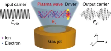
Concept of plasma optical modulators. The concept of the plasma optical modulator is illustrated in Fig. 1: a linearly polarized femtosecond intense drive laser pulse propagates in a
sub-mm-scale gas, forming an underdense plasma via field ionization. Meanwhile, the ponderomotive force of the laser pulse drives the plasma electrons out of its path. Because the plasma ions are much heavier (by a factor of at least 1,836), they barely move and remain unshielded. The resultant pattern of alternating positive and negative charge-separation fields behind the laser driver is a plasma wave (also called laser wakefields), which has been well-described theoretically19 and measured experimentally37. The wave oscillates at the plasma frequencyop,
whereop¼ðn0e2=meE0Þ1
=2
, withn0the ambient electron plasma
density, E0 the permittivity of free space, and me and e the
electron rest mass and charge, respectively. For the purpose of optical modulation, the plasma wave is driven at a moderate amplitude. A picosecond carrier laser pulse (with an arbitrary polarization direction) co-propagates behind the drive laser with a delay of several plasma wavelengths. The amplitude and frequency of the carrier are simultaneously modulated by the plasma wave during its propagation, generating a number of significant frequency sidebands spaced by the plasma frequency in the frequency domain. The modulation speedfpis determined
by the plasma frequency op, which can be estimated as
fpðHzÞ ¼op=2p ’ 8;980
ffiffiffiffiffiffiffiffiffiffiffiffiffiffiffiffiffiffiffiffi
n0ðcm3Þ p
, for example,fpC28 THz for n0¼1019cm3, which is several orders of magnitude faster
than the speed of an EOM. Particle-in-cell (PIC) simulations show that such plasma modulators can sustain a carrier intensity up to 1016W cm2, which is several orders of magnitude higher than what conventional EOMs can handle.
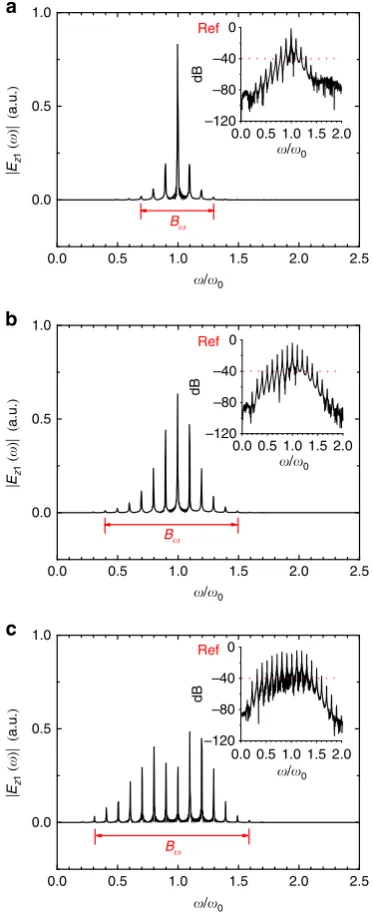
Parameter dependence of modulation strength. Figure 2 shows an example case to demonstrate the essential features of the modulation obtained from one-dimensional (1D) PIC simula-tions. For simplicity, the vacuum wavelengths of the two laser pulses are both 1mm in the simulations. In practice, an 800-nm Ti:sapphire femtosecond laser pulse can be used to excite the plasma waves, which does not lead to obvious changes of the results presented in the following. The normalized field ampli-tudes of the driver and the unmodulated carrier area00¼0.8 and
a10¼0.05, respectively, where ai0¼Ezi0/En (i¼0,1), and En¼ meco0/e, withcando0the light speed and angular frequency in
vacuum, respectively. For linear polarization, Ii0(W cm2)
¼1.371018ai20/[l0(mm)]2, withIi0the peak laser intensity and l0¼2pc/o0 the laser wavelength in vacuum. Thus,a00 anda10
correspond to the laser intensities of 8.771017 and 3.43 1015W cm2, respectively, for 1mm laser wavelength. Detailed parameters are given in the Methods. The modulated pulse is well described using the analytical model presented in the Methods. It
Gas jet
Input carrier Plasma wave Driver Output carrier
x y z
Ez10 Ex Ez1
[image:2.595.337.519.568.652.2]Ion Electron
Figure 1 | Schematic of a plasma optical modulator.A linearly polarized
can be expressed as a1(t)¼a10[1þm cos(opt)] cos[o0tþb
sin(opt)], where m and b are the amplitude modulation index
and the frequency modulation index, respectively. The mixed amplitude and frequency modulation of a sinusoidal carrier by a simple sinusoidal plasma wave yields a mass of sidebands including both Stokes and anti-Stokes components given by
on¼o0±nop(withna nonzero integer andopas a frequency
interval). Note that in the quasi-linear regime of the plasma wave, that is, where the relativistic-electron-mass increase associated with the motion of the plasma electrons can be neglected, the frequency op can be calculated as op¼(n0/nc)1/2o0, with
nc(cm3)¼1.11021/[l0(mm)]2 the critical plasma density for
the corresponding incident laser wavelength l0. The spectral
bandwidth is defined as Bo¼2(bþ1)op (ref. 38), where b depends on the amplitude of the drive pulse and the plasma density, in addition to the plasma length.
For high fidelity, we only count the significant sidebands with the amplitudes larger than 1% (40 dB) of the amplitude of the unmodulated carrier38. Therefore, the spectral bandwidth of the modulated carrier can be calculated by estimating the number of significant sidebands. As shown in Fig. 2, the higher-order sidebands gradually grow with the laser–plasma interaction time. When the carrier pulse completely passes through the plasma, the maximum significant sidebands for the anti-Stokes and Stokes components are oþ6 and o7, respectively, giving a
bandwidth of Bo¼13op¼1.3o0, accounting for the fact that op¼0.1o0 for n0/nc¼0.01. It is also noted that the
sideband spectrum of a mixed modulation is asymmetrical due
to the superposition of the sideband components of
both amplitude and frequency modulations. The simulation results are in good agreement with the prediction of the analytical model given in the Methods. In this example, the amplitude and frequency modulation indices can be estimated38 as m¼(a10,maxa10,min)/(a10,maxþa10,min)¼0.42,
and b¼Bo/(2op)1¼5.5, respectively. Note that bc1
corresponds to broadband modulation. The energy transmission rate of the carrier through plasma isB94.3% in this example.
We find the modulation is effective for a wide range of
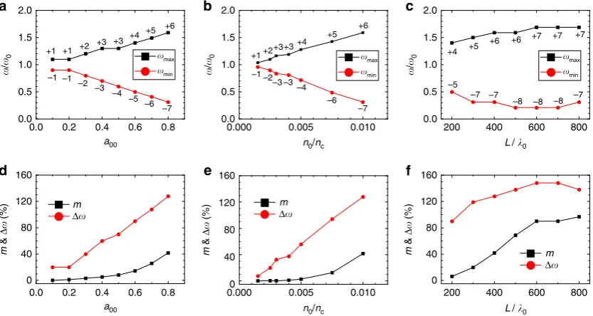
laser–plasma parameters. Figure 3 shows the 40 dB
cutoff sidebands, the corresponding fractional bandwidth (Do¼Bo/o0), and the amplitude modulation index m, as a
function of the driver intensity, the plasma density and the plasma length. When the driver amplitude is relatively small (for example,a00¼0.1), the modulation is quite weak so that the
spectrum only consists of the first-order sidebands. By increasing the driver amplitude, the field strength of the plasma wave is enhanced, and subsequently the modulation indices become larger, leading to higher-order sidebands and a wider bandwidth. The similar scaling law exists when increasing the plasma density. Therefore, by properly increasing the drive laser intensity and the plasma density, one can extend the spectrum of the modulated carrier to the mid-infrared regime in the low-frequency side (or the Stokes waves). We note that the growth of the bandwidth is relatively insensitive to the increase of the plasma length after certain distance, which implies a saturation of modulation. As shown in Fig. 3d–f, the amplitude modulation index m gradually grows with the increase of the driver intensity or the plasma density. When increasing the plasma length,mfirst grows and then saturates at the 100% level, which indicates that the carrier breaks up into a train of short pulses, and each of these short pulses has a width on the order of the plasma wavelength. According to Fig. 3d–f,Doandbhave similar dependence on the driver intensity, the plasma density and the plasma length asm. In the simulation results given above, we have limited the plasma wave excitation to the quasi-linear regime (when the driver laser amplitude a00t1). This avoids possible occurrence of curved
plasma wave fronts and plasma wave breaking, so that the carrier laser pulse can be modulated efficiently.
For certain applications, it is important to know the parameter range for broad bandwidth generation. Figure 4 illustrates the parameter constraint for generating carrier pulses with ultrabroad bandwidths (for example, Do Z30%), which presents a series
of simulations where the threshold for the driver amplitudea00,th
is scanned for a given plasma density n0. In general, a broader
bandwidth can be achieved at a higher plasma density even if a lower driver intensity is adopted.
0.0 0.5 1.0 1.5 2.0 2.5
0.0 0.5 1.0
0
–40
–80
–120
0.0 0.5 1.0 1.5 2.0 Ref
a
dB
B
0.0 0.5 1.0 1.5 2.0 2.5
0.0 0.5 1.0
0
–40
–80
–120
0.0 0.5 1.0 1.5 2.0 Ref
b
dB
B
0.0 0.5 1.0 1.5 2.0 2.5
0.0 0.5 1.0
0
–40
–80
–120
0.0 0.5 1.0 1.5 2.0 Ref
c
dB
B
⎢
Ez
1
(
) ⎢
(
a.u.
)
⎢
Ez
1
(
) ⎢
(
a.u.
)
⎢
Ez
1
(
) ⎢
(
a.u.
)
/0
/0
/0
/0
/0
[image:3.595.74.261.53.510.2]/0
Figure 2 | Evolution of the frequency spectrum of the carrier laser.The
front of the carrier enters the plasma att¼50TL. (a,b,c) The spectra of the carrier at the propagation time oft¼250TL,t¼400TLandt¼750TL(when the carrier completely passes through the plasma), respectively.
In passing, we mention that, even though the frequencies of the drive laser pulse and the carrier laser pulse can be different in a certain range and the time delay between them can also be arbitrary within a picosecond, the plasma optical modulator requires that the two pulses co-propagate, that is, there is almost no frequency modulation when they counter-propagate.
Discussion
So far we have discussed the spectrum development of the carrier laser pulse as a function of the drive laser amplitude, the plasma density, and the plasma length. One question still to be answered is the maximum carrier laser intensity allowed in the plasma modulator. A previous study has shown that the resultant pulse train can amplify the field strength of the plasma wake to a wave-breaking level if the initial intensity of the carrier laser is high enough39. We also find the remarkably enhanced plasma
waves when the intensity of the pulse train is on the same order of the driver intensity (for example, 1017W cm2level). This can result in severe distortion of the plasma wave and considerable energy loss of the carrier laser to plasma wave excitation as well as electron trapping and acceleration (see Supplementary Fig. 1 and Supplementary Note 1). As a consequence, the frequency modulation of the carrier laser is suppressed. Therefore, the maximum intensity of the carrier laser should be well below 1017W cm2 (for example, at 1016W cm2 level) to realize an excellent performance of the plasma optical modulator.
The maximum allowed pulse duration of the carrier laser for effective modulation may be interesting for some particular applications. This depends on the life time of the electron plasma waves, which is determined by the collisional damping, Landau damping and phase mixing40,41. Typically the initial electron plasma temperatureTeis over 10 eV and the effectiveTeis over
100 eV when considering the electron quiver motion in the carrier laser with intensityB1016W cm2, which leads to a time scale of over 10 ps for the collisional damping under the plasma electron density of B1019cm3. The Landau damping time is much longer than the collisional damping time in the present case when the plasma wave is driven at moderate amplitudes. The phase mixing due to the ion motion is the key responsibility for the plasma wave decay since it occurs on a much shorter time scale of tmix op1½ðA2=24Þðme=miÞ1=3 1:47 ps (ref. 40)
when a high-Z gas such as argon is used for the plasma wave excitation, where A¼Emax=Ep a200=2 is the normalized
amplitude of the plasma wave, with Ep¼cmeop/e and mi the
ion mass. PIC simulations show that the plasma wave starts to decay around 1.65 ps due to the phase mixing, which is in good agreement with the analytical model. The maximum pulse duration for the effective modulation is around 3 ps for the laser–plasma parameters under consideration (see Supplementary Fig. 2, Supplementary Fig. 3 and Supplementary Note 2).
Another issue is the spot sizes of the laser pulses. As we have shown above, the laser pulses need to propagate over a distance of about 1 mm without significant transverse spreading. One needs to take relatively large spot sizes so that the corresponding Rayleigh lengthspr2
i=l0are long enough, withri(i¼0,1) the spot 2.0
1.5
1.0
0.5
0.0
0.0 0.2 0.4 0.6 0.8
a00
0.0 0.2 0.4 0.6 0.8
0 40 80 120 160
m m
m
&
Δ
(%)
m
&
Δ
(%)
m
&
Δ
(%)
2.0
1.5
1.0
0.5
0.0
0.000 0.005 0.010
n0/nc L/ 0
a00 n0/nc L/ 0
0.0000 0.005 0.010
40 80 120 160
2.0
1.5
1.0
0.5
0.0
200 400 600 800
m
0 40 80 120 160
200 400 600 800
a b c
d e f
Δ Δ
Δ max
min
max
min
max
min +1
–1 –1 –2
–3 –4
–5 –6
–7 +1 +2
+3 +3 +4 +5 +6
+1
–1 –2–3 –3 –4
–6 –7
–5 +4 +5
+6 +6 +7 +7 +7
–7 –7
–8 –8 –8 –7 +2+3+3
+4 +5
+6
/
0
/
0
/
[image:4.595.91.508.52.274.2]0
Figure 3 | Performance metrics of the plasma optical modulator.(a–c) The 40 dB sidebands versus (a) the driver amplitude, (b) the plasma density
and (c) the plasma length. (d–f) The 40 dB fractional bandwidthDoand the amplitude modulation indexmversus (d) the driver amplitude, (e) the plasma density and (f) the plasma length. The other laser–plasma parameters are the same as in Fig. 2.
0.000 0.005
Δ> 30% Δ> 50%
0.010 0.2
0.4 0.6 0.8 1.0
a00,th
[image:4.595.77.263.341.487.2]n0/nc
Figure 4 | Constraint on the drive laser amplitude and the plasma density
for broad bandwidth generation.Threshold driver amplitude versus the
sizes of the two laser pulses. Meanwhile, self-focusing will occur when the driver power P exceeds a critical power Pc, with Pc
(GW)¼17.4(o0/op)2. For linear polarization,P/Pc¼(opr0a00)2/
(32c2) (ref. 19). To avoid strong self-focusing within 1 mm, the spot size of the driver cannot be too large, either. Two-dimensional (2D) simulations show that the optimal modulation can be achieved for 1tP/Pct2. An example of 2D simulation is
given in Fig. 5. Detailed parameters are given in the Methods. In this example, the driver power is P/Pc¼1.18 and weak
self-focusing occurs during the propagation. As shown in Fig. 5a, the maximum amplitude of the driver increases by 10% (from a00¼0.7 to 0.77) at a propagation distance of 392l0.
The excited plasma wave retains the quasi-1D structure, and keeps quite stable during propagation, which is advantageous for the modulation process. It is noted that the driver spot leads to transverse inhomogeneity of the plasma wave, resulting in transverse inhomogeneity of the modulation. By reducing the driver intensity, the corresponding spot size can be increased, and hence, the transverse uniformity of the modulation can be improved.
The technical essentials of realizing the proposed plasma modulators are well within current capabilities. First, the plasma wave excitation by an ultrashort pulse is a well-known technique, which has been widely adopted for laser wakefield accelerators (LWFAs)19. For the application to plasma optical modulators, the required amplitude of the plasma wave can be much smaller than that for LWFAs, implying that only moderate drive laser power, such as a few terawatts, is required. Second, the frequencies of the carrier pulse and the drive pulse and the time delay between them are relatively flexible, indicating that the experimental configuration is simpler as compared with some other experiments involving two colliding lasers such as Raman amplification30, superradiant amplification42and colliding laser pulses injection in LWFAs43. A test experiment of the plasma optical modulator could be carried out with a carrier laser pulse
(for example, Nd:YVO4, 1mm, B15 mJ, B1 ps) delayed with
respect to a drive laser pulse (for example, Ti:sapphire, 0.8mm,
B150 mJ, B30 fs), co-propagating in a 1-mm-long helium gas with a density ofB1019cm3. The time delay between the two laser pulses can be controlled in a timescale of hundreds of femtoseconds.
In summary, we have illustrated a novel application of the plasma wave as a unique optical modulator for intense lasers. It relies on two co-propagating laser pulses in a short underdense plasma: a driver with a typical intensityB1017W cm2, which propagates in the plasma and excites a plasma wake, and a carrier, which propagates behind the driver by several plasma wavelengths. Both the amplitude and frequency of the carrier are modulated by the plasma wave, leading to an ultrabroad bandwidth in its spectrum that extends to the mid-infrared range. The modulation speed is in the THz regime. Compared with the low-damage threshold of the conventional EOMs, the plasma modulator allows the carrier intensity as high as up to 1016W cm2. In addition, the plasma modulator offers excellent performance control by changing the driver intensity, the plasma density and the plasma length. The required experimental conditions for such plasma modulators are within current technical capabilities.
Methods
Mathematical model for mixed modulation.Physically, the modulation of the
carrier laser pulse by an electron plasma wave is similar to that found for an intense laser propagation in plasma via stimulated Raman forward scattering (coupled with the self-modulation instability)44,45. The latter leads to a spectrum of Stokes and anti-Stokes waves when the laser pulse has a duration longer than a plasma wavelength. The evolution of the amount of Stokes/anti-Stokes modes can be described by photon acceleration and deceleration46–48. The dependence of the spectral modulation on the plasma wave amplitude, the plasma density and the interaction time discussed in the above section also qualitatively agrees with the previous theories. The difference between the spectral modulation described in the previous theories and here is that our plasma optical modulator enables the
40 220 400
–50 0 50
y
/
0
–0.76 0.77
700 800 900 1,000
–0.2 –0.1 0.0 0.1 0.2
–0.024 0.024
40 220 400
–50 0 50
Ex /En Ez /En
1.0
0.5
0.0
Ez
1
/
En
a b
c d
⎢
Ez
1
(
) ⎢
(
a.u.
)
B
0.0 1.0 2.0
x/0
x/0
/0
x/0
y
/
[image:5.595.135.462.49.312.2]0
Figure 5 | Two-dimensional simulation results.Snapshots of (a) the electric fields of the two laser pulses, (b) the longitudinal electric field of the plasma
spectral modulation of the carrier laser to be well controlled and to be developed much more efficiently.
The carrier pulse is modulated in the amplitude and frequency by the electron plasma wave, that is, a mixed modulation. Its temporal structure can be written as49
a1ðtÞ ¼a101þmcos opt
coso0tþbsinopt
; ð1Þ
assuming that the excited plasma wave is a simple sinusoidal oscillation, with the normalized axial electric fieldEx/Ep¼(Emax/Ep) cos(opt) (ref. 19). Herea10is the normalized amplitude of the unmodulated carrier. For a linearly polarized sinusoidal driver with an optimal pulse length for plasma wave excitation (that is, the pulse length approximate to the plasma wavelength),Emax=Ep a200=2, yielding the amplitude and frequency modulation indicesm/a2
00=ð2a10Þand b/ ða2
00=2Þ o0=op
[image:6.595.97.282.228.292.2]
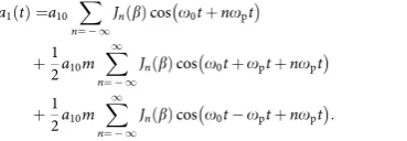
, respectively. These two parameters also depend on the interaction time or the plasma length as shown in the simulation results given in Fig. 3. Using simple trigonometrical transformations and a lemma of Bessel function andJn(b)¼(1)nJn(b),a1(t) can be written as
a1ðtÞ ¼a10 X1
n¼ 1
JnðbÞcoso0tþnopt
þ1 2a10m
X1
n¼ 1
JnðbÞcoso0tþoptþnopt
þ1 2a10m
X1
n¼ 1
JnðbÞcoso0toptþnopt:
ð2Þ
It is obvious that the spectrum ofa1(t) primarily consists of three components: the central frequencyo0that corresponds to the unmodulated carrier, and the two first-order sidebandso±1¼o0±opresulting from the modulation process. The amplitudes of the frequency components can be characterized by the expansion in a series ofnth-order Bessel functionJn. By taking Fourier transformation ofa1(t), and considering thekth-order frequency component withka positive integer, we can get the amplitudes of the upper sideband (oþk¼o0þkop) and the lower sideband (ok¼o0kop) in the spectrum as follows:
a1ðoþkÞ
j j ¼pffiffiffiffiffi2p=2a10j½JkðbÞ þ ðm=2ÞJk1ðbÞþ ðm=2ÞJkþ1ðbÞj; ð3Þ a1ðokÞ
j j ¼pffiffiffiffiffi2p=2a10j½JkðbÞ ðm=2ÞJk1ðbÞ ðm=2ÞJkþ1ðbÞj; ð4Þ foro±k40. From equations (3) and (4), it is straightforward to see that the
amplitude of the lower sideband is not equal to the amplitude of the corresponding upper sideband, leading to an asymmetrical sideband spectrum. For a weak frequency modulation (0oboo1), the modulation index is so small that the spectrum essentially consists ofo0and only one set of sidebandso±1, with the amplitudes ofja1ðoþ1Þj ¼
ffiffiffiffiffi 2p p
=4
ðmþbÞa10, and
a1ðo1Þ
j j ¼pffiffiffiffiffi2p=4jmbja10. For a large modulation index (b41), there will be a number of significant sidebands spanning over a broad frequency range.
It is worthwhile to mention that when the excited plasma wave is nonlinear, there are high-harmonic components of the plasma oscillations. This leads to an additional frequency modulation at harmonics of the plasma frequency, which are superimposed on the sidebands discussed above, contributing to more energetic sidebands. This nonlinear effect has been included in our self-consistent PIC simulation results presented above.
PIC simulations.Simulations have been carried out using the code OSIRIS50. In the
1D simulations (for example, in Fig. 2), the temporal profile of the drive pulse is a0ðtÞ ¼a00sin2ðpt=T0Þ, with 0rtrT0andT0¼10TL. The carrier pulse, which is delayed by 40l0from the driver, has a duration ofT1¼303TL. It has a similar profile as the driver at its leading and trailing edges, and a plateau of 283TLin between. The amplitudes of the driver and the carrier area00¼0.8,a10¼0.05, respectively. The trapezoid-shaped plasma has a length of 400l0with a plateau of 380l0, located betweenx¼10l0andx¼410l0. The initial plasma electron density in the plateau region is set to ben0/nc¼0.01. For laser-driven plasma waves, typically the initial (photoionized) electron plasma temperature is set to be 10 eV. The simulation box size is 800l0with 20 macro-particles per cell. The resolution of the computational grid isDx¼l0/40. Att¼0, the front of the driver enters the simulation box. In the 2D simulation (Fig. 5), the amplitude of the driver isa00¼0.7 and the spot sizes of the driver and the carrier arer0¼14l0andr1¼17l0, respectively. The trapezoid-shaped plasma has a length of 700l0. Other laser–plasma parameters are the same as the 1D simulations. The simulation box size is 1,100l0100l0with four macro-particles per cell. The resolution of the computational grid isDx¼l0/32 and
Dy¼l0/20.
Data availability.The data that support the findings of this study are available
from the corresponding authors upon request.
References
1. Liu, K., Ye, C. R., Khan, S. & Sorger, V. J. Review and perspective on ultrafast wavelength-size electro-optic modulators.Laser Photon Rev.9, 172–194 (2015).
2. Reed, G. T., Mashanovich, G., Gardes, F. Y. & Thomson, D. J. Silicon optical modulators.Nat. Photon4,518–526 (2010).
3. Liu, M.et al.A graphene-based broadband optical modulator.Nature474, 64–67 (2011).
4. Phare, C. T., Lee, Y.-H. D., Cardenas, J. & Lipson, M. Graphene electro-optic modulator with 30 GHz bandwidth.Nat. Photon9,511–515 (2015). 5. Seeds, A. J. & Williams, K. J. Microwave photonics.J. Lightwave Technol.24,
4628–4641 (2006).
6. Capmany, J. & Novak, D. Microwave photonics combines two world.Nat. Photon1,319–330 (2007).
7. Melikyan, A.et al.High-speed plasmonic phase modulators.Nat. Photon8, 229–233 (2014).
8. Macario, J.et al.Full spectrum millimeter-wave modulation.Opt. Express20, 23623–23629 (2012).
9. Chen, D.et al.Demonstration of 110 GHz electro-optic polymer modulators. Appl. Phys. Lett.70,3335–3337 (1997).
10. Huang, H.et al.Broadband modulation performance of 100-GHz EO polymer MZMs.J. Lightwave Technol.30,3647–3652 (2012).
11. Bryan, D. A., Gerson, R. & Tomaschke, H. E. Increased optical damage resistance in lithium niobate.Appl. Phys. Lett.44,847–849 (1984). 12. Furukawa, Y., Sato, M., Kitamura, K., Yajima, Y. & Minakata, M. Optical
damage resistance and crystal quality of LiNbO3 single crystals with various [Li]/[Nb] ratios.J. Appl. Phys.72,3250–3254 (1992).
13. Furukawa, Y.et al.Investigation of bulk laser damage threshold of lithium niobate single crystals by Q-switched pulse laser.J. Appl. Phys.69,3372–3374 (1991).
14. Newport Corporation. Electro-optic modulator guide. Available at http://www.newport.com/Electro-Optic-Modulator-Selection-Guide/977460/ 1033/content.aspx?xcid=bing-ppc-0244.
15. Paul, A.et al.Quasi-phase-matched generation of coherent extreme-ultraviolet light.Nature421,51–54 (2003).
16. Thomson, M. D., Kre, M., Lo¨ffler, T. & Roskos, H. G. Broadband THz emission from gas plasmas induced by femtosecond optical pulses: From fundamentals to applications.Laser Photon Rev.1,349–368 (2007). 17. Chen, Y.et al.Elliptically polarized Terahertz emission in the forward direction
of a femtosecond laser filament in air.Appl. Phys. Lett.93,231116 (2008). 18. Cho, M.-H.et al.Strong terahertz emission from electromagnetic diffusion near
cutoff in plasma.New J. Phys.17,043045 (2015).
19. Esarey, E., Schroeder, C. B. & Leemans, W. P. Physics of laser-driven plasma-based electron accelerators.Rev. Mod. Phys.81,1229–1285 (2009). 20. Glenzer, S. H.et al.Symmetric inertial confinement fusion implosions at
ultra-high laser energies.Science327,1228–1231 (2010).
21. Zhong, J.-Y.et al.Modelling loop-top X-ray source and reconnection outflows in solar flares with intense lasers.Nat. Phys.6,984–987 (2010).
22. Leemans, W. P.et al.GeV electron beams from a centimetre-scale accelerator. Nat. Phys.2,696–699 (2006).
23. Leemans, W. P.et al.Multi-GeV electron beams from capillary-discharge-guided subpetawatt laser pulses in the self-trapping regime.Phys. Rev. Lett.113, 245002 (2014).
24. Thaury, C.et al.Plasma mirrors for ultrahigh-intensity optics.Nat. Phys.3, 424–429 (2007).
25. Andreev, A. A.et al.Optimal ion acceleration from ultrathin foils irradiated by a profiled laser pulse of relativistic intensity.Phys. Plasmas16,013103 (2009). 26. Wu, H.-C., Sheng, Z.-M., Zhang, Q.-J., Cang, Y. & Zhang, J. Manipulating
ultrashort intense laser pulses by plasma Bragg gratings.Phys. Plasmas12, 113103 (2005).
27. Wang, H.-Y.et al.Laser shaping of a relativistic intense, short Gaussian pulse by a plasma lens.Phys. Rev. Lett.107,265002 (2011).
28. Trines, R. M. G. M.et al.Simulations of efficient Raman amplification into the multipetawatt regime.Nat. Phys.7,87–92 (2011).
29. Mourou, G. A., Tajima, T. & Bulanov, S. V. Optics in the relativistic regime. Rev. Mod. Phys.78,309–371 (2006).
30. Yang, X.et al.Chirped pulse Raman amplification in warm plasma: towards controlling saturation.Sci. Rep.5,13333 (2015).
31. Wen, H., Daranciang, D. & Lindenberg, A. M. High-speed all-optical terahertz polarization switching by a transient plasma phase modulator.Appl. Phys. Lett. 96,161103 (2010).
32. Rice, A.et al.Terahertz optical rectification fromo1104zinc-blende crystals. Appl. Phys. Lett.64,1324–1326 (1994).
33. Chang, Z., Rundquist, A., Wang, H., Murnane, M. M. & Kapteyn, H. C. Generation of coherent soft X rays at 2.7 nm using high harmonics.Phys. Rev. Lett.79,2967–2970 (1997).
35. Thomson, J. & Karush, J. I. Effects of finite-bandwidth driver on the parametric instability.Phys. Fluids17,1608–1613 (1974).
36. Zhao, Y.et al.Effects of large laser bandwidth on stimulated Raman scattering instability in underdense plasma.Phys. Plasmas22, 052119(1)–052119(7) (2015).
37. Matlis, N. H.et al.Snapshots of laser wakefields.Nat. Phys2,749–753 (2006). 38. Agilent Technologies. Spectrum analysis amplitude and frequency
modulation. Available at http://cp.literature.agilent.com/litweb/pdf/5954-9130.pdf (2001).
39. Sheng, Z.-M., Mima, K., Sentoku, Y., Nishihara, K. & Zhang, J. Generation of high-amplitude plasma waves for particle acceleration by cross-modulated laser wake fields.Phys. Plasmas9,3147–3153 (2002).
40. Gupta, S. S. & Kaw, P. K. Phase mixing of nonlinear plasma oscillations in an arbitrary mass ratio cold plasma.Phys. Rev. Lett.82,1867–1870 (1999). 41. Xu, H., Sheng, Z.-M. & Zhang, J. Phase mixing due to ion motion and relativistic
effects in nonlinear plasma oscillations.Phys. Scr.74,673–677 (2006). 42. Dreher, M., Takahashi, E., Meyer-ter-Vehn, J. & Witte, K.-J. Observation of
superradiant amplification of ultrashort laser pulses in a plasma.Phys. Rev. Lett. 93,095001 (2004).
43. Faure, J.et al.Controlled injection and acceleration of electrons in plasma wakefields by colliding laser pulses.Nature444,737–739 (2006). 44. Mori, W. B. The physics of the nonlinear optics of plasmas at relativistic
intensities for short-pulse lasers.IEEE J. Quantum Electron.33,1942–1953 (1997). 45. Tzeng, K.-C., Mori, W. B. & Katsouleas, T. Self-trapped electron acceleration
from the nonlinear interplay between Raman forward scattering, self-focusing, and hosing.Phys. Plasmas6,2105–2116 (1999).
46. Wilks, S. C., Dawson, J. M., Mori, W. B., Katsouleas, T. & Jones, M. E. Photon accelerator.Phys. Rev. Lett.62,2600–2603 (1989).
47. Esarey, E., Ting, A. & Sprangle, P. Frequency shifts induced in laser pulses by plasma waves.Phys. Rev. A42,3526–3531 (1990).
48. Sheng, Z.-M., Ma, J.-X., Xu, Z.-Z. & Yu, W. Effect of an electron plasma wave on the propagation of an ultrashort laser pulse.J. Opt. Soc. Am. B10,122–129 (1993).
49. Ozimek, E. & Sek, A. Perception of amplitude and frequency modulated signals (mixed modulation).J. Acoust. Soc. Am.82,1598–1603 (1987).
50. Fonseca, R. A.et al.OSIRIS, a three-dimensional fully relativistic particle in cell code for modeling plasma based accelerators.Lect. Notes Comput. Sci.2331, 342–351 (2002).
Acknowledgements
We thank Thomas Sokollik, Yulong Tang, Jun Zheng, Yanping Chen and Guoqiang Xie for useful discussions. This work was supported by the National Basic Research Program of China under grant no. 2013CBA01500, 2014CB339801 and 2015CB859700, the National Natural Science Foundation of China under grant nos 11421064, 11405107 and 11475113. D.A.J. and Z.M.S. acknowledge the support of the U.K. EPSRC (grant no. EP/J018171/1), the EC’s LASERLAB-EUROPE (grant no. 654148), EuCARD-2 (grant no. 312453), EuPRAXIA (grant no. 653782) and a Leverhulme Trust Research Project Grant. Simulations have been carried out on the PI supercomputer at Shanghai Jiao Tong University and the Milky Way 2 supercomputer in the National Supercomputer Center in Guangzhou.
Author contributions
L.L.Y. and Z.M.S. designed the overall concept presented in this paper. L.L.Y. carried out all the simulations and the analytical model, and wrote the main manuscript text. Z.M.S., Y.Z., L.J.Q., M.C., S.M.W., D.A.J., W.B.M. and J.Z. contributed to analyse the results and write the manuscript. All authors discussed the results and commented on the manuscript.
Additional information
Supplementary Informationaccompanies this paper at http://www.nature.com/ naturecommunications
Competing financial interests:The authors declare no competing financial interests.
Reprints and permissioninformation is available online at http://npg.nature.com/ reprintsandpermissions/
How to cite this article:Yu, L.-L.et al.Plasma optical modulators for intense lasers. Nat. Commun.7:11893 doi: 10.1038/ncomms11893 (2016).