Enhanced Control Strategy of Full-Bridge Modular
Multilevel Converter
G.P. Adam,
IEEE
member, S.J. Finney and B.W. Williams
University of Strathclyde
Abstract—This paper describes a control approach that allows the cell capacitor voltages of the full-bridge modular multilevel converter (FB-MMC) to be controlled independent of the input dc link voltage. Moreover, this control approach offers the possibility of operating FB-MMC from bi-polar dc link voltages; thus, creating new possibilities for building generic hybrid dc grids with reversible dc link voltage, where the conventional line commutated current source converters can operate alongside voltage source converters. Furthermore, the presented control approach improves the dc fault ride-through of the FB-MMC compared to existing approaches. This could be achieved by an active control of the arm currents and cell capacitor voltages, and full exploitation of the MMC redundant switch states. Operation of the FB-MMC with reversible DC link voltage and decoupled control of the cell capacitor voltages from the dc link voltage are demonstrated using simulations. The major findings and implications of this work are highlighted.
Key words—dc fault ride-through capability; dc short circuit proof; high-voltage dc transmission systems; half and full bridge modular multilevel converters; and line commutated converter.
I.
I
NTRODUCTIONThe growing demand for low carbon technologies in the last decade in effort to mitigate the effect of global warming has accelerated the development of renewable power generations that rely increasingly on the use of power electronics. Voltage source converter high-voltage dc (VSC-HVDC) transmission is seen as a key facilitator for the integration of these renewable power plants into ac grids. Early generations of VSC-HVDC links are built around the two-level and neutral-point clamped (NPC) converters. But these converters suffer from high semiconductor losses and expose interfacing transformers to intolerable voltage stresses (dv/dt). These stresses will be acerbated should the dc operating voltage of these HVDC links to be raised to increase their power capacity. Additionally, the use of the concentrated dc link capacitors makes VSC-HVDC links vulnerable to dc faults as converter switching devices are exposed to high current stresses due to discharge of the dc link capacitors, and uncontrolled ac in-feed current toward dc side during dc side faults.
Half and full-bridge modular multilevel converters (HB/FB-MMC) have emerged as attractive topologies for high-voltage applications. They offer the following features: scalable to high voltage without the need for series device connection; modular
structure with internal fault management (while the system remains operational); and relatively low semiconductor losses[1]. The use of distributed cell capacitors in the HB-MMC improves its dc fault ride capability as the magnitude of uncontrolled ac in-feed currents that may flow in the converter switches during dc fault is significantly reduced (as cell capacitors do not contribute to fault current). Blocking of FB-MMC switching advices during a dc fault is sufficient to eliminate ac grid contribution to dc fault current. Although this feature is attractive, the FB-MMC has higher semiconductor losses than the HB-MMC (2.35 times according to reference [1]). Although there are several alternative converter topologies offer dc fault short circuit proof capability with relatively low semiconductor losses, half and full bridge MMCs remain the industry preferred topologies.
Different aspects HB and FB-MMCs have been studied in recent years. For example, the basic operational principle, modulation and capacitor voltage balancing of the MMC are discussed in[2-6]. The authors in [5, 7, 8] adopted the use of a single reference per phase for both sinusoidal pulse width modulation and staircase modulation with the nearest voltage levels. These references have demonstrated the possibility of using output phase currents rather than the arm currents for control and capacitor voltage balancing. However, the use of a single reference increases the number of switching combinations that can be used to maintain cell capacitor voltage balancing, which make generalization of this approach more challenging.
The use of two reference signals per phase (one per arm) for controlling the MMC using pulse width (level shifted phase disposition) and staircase modulation is proposed in [9]. This approach is widely used because it makes MMC modulation generalisation simpler than that in [5, 7, 8].
PWM with number of control loops for cell capacitor voltages, arm current balancing, circulating current suppression, and individual cell capacitor voltage balancing, to ensure stable system operation, independent of operating conditions. The validity of the control approach in [11, 15-17] is confirmed using simulation and experimentation. However, the increased control reliance in order to maintain cell capacitor voltage balancing may lead to system collapse from any control system malfunction, which is not the case in the traditional approaches. This approach is therefore less likely to be adopted in HVDC applications.
Most of the approaches that regulate arm currents use some form of average cell capacitor voltage regulation originally suggested by Akagi and others in [11, 15-18]. However, increased reliance of these methods on the use of control within the modulator or in main control path may raise several concerns regarding their robustness during ac and dc network faults, and malfunction of the control systems.
This paper presents control approach that uses the unexploited possibilities within the FB-MMC power circuit to decouple its cell capacitor voltage regulation from the dc link voltage; thus, breaking the link between ac voltage generation and dc link. The viability of the presented control scheme is demonstrated using simulation, considering operation of FB-MMC with a positive and negative dc link voltage. Also, this paper explores different FB-MMC operating modes and their potential uses in HVDC transmission systems. DC fault survival which is not covered here can be found in [19].
II.
M
ODULATION AND CONTROL OF THEFB-MMC
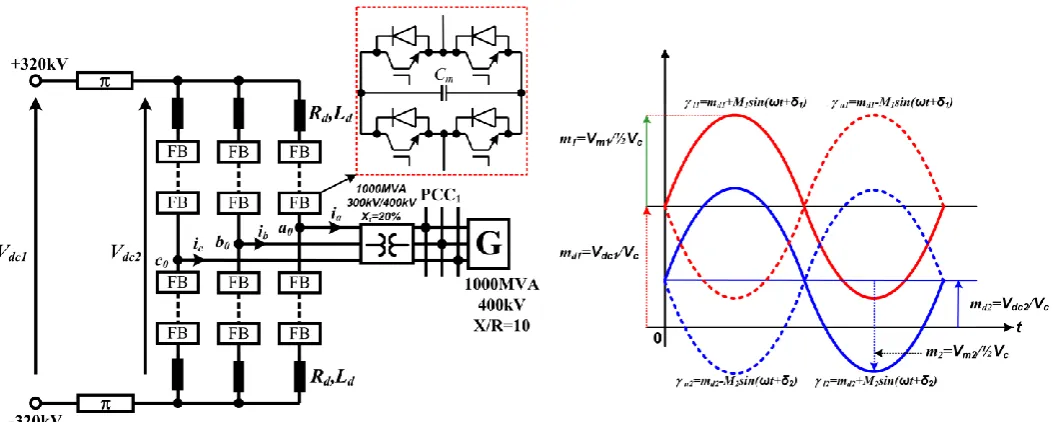
Figure 1 shows a three-phase generic FB-MMC with N cells per arm. Voltage stress across each FB=MMC cell capacitor and switching device must be maintained at Vdc/N, and each
arm must block full dc link voltage Vdc. Unlike unipolar cells of
the HB-MMC, each bipolar cell of the FB-MMC can generate three voltage levels ± Vdc/N and 0. This allows the FB-MMC
cell capacitors to be inserted with positive or negative polarities relative to dc link voltage Vdc to generate different voltage
levels at the converter output poles ‘a0’, ‘b0’ and ‘c0’ relative to
the supply mid-point. Figure 1and Figure 2 illustrate the pulse width modulation strategy use in this paper for controlling the FB-MMC, assuming a fixed modulation index (M) and adjustable dc offset (md), where the upper and lower arm
modulation functions of phase ‘a’ are described as
va1=½Vdc(md+ma) and va2=½Vdc(md-ma), and ma=Msinωt and
-1≤md≤1(md=Vdc/Vc). During normal operation, FB-MMC dc
link voltage is regulated around rated voltage, so 0≤va1/Vdc≤1
and 0≤va2/Vdc≤1 as md1. In this operating mode, FB-MMC
operates in buck mode; thus, voltage levels at converter output poles (a0, b0 and c0) are generated by insertion of the FB cell
capacitors with opposing polarities to that of the input dc link voltage (only subtractive states are utilized). Also, cell capacitor insertion with the same voltage polarity as the dc link (additive states) is allowed only during the intermediate voltage levels to accelerate cell capacitor voltage balancing. When the dc link voltage is reduced below the peak of the line-to-line ac voltage, the FB-MMC must be operated in a boost mode in order to retain full control over its active and reactive power exchange with the ac grid. In this mode, insertion of the FB cell capacitors with the same voltage polarity as the input dc link voltage (additive states) can be utilized to allow the cell capacitors of each converter arm to be used as virtual dc links, provided the sum of the cell capacitor voltages of each arm is regulated around the rated dc operating voltage (even when the dc link is suppressed to zero as during a pole-to-pole dc short-circuit fault). With the modulation strategy depicted in Figure 1 and Figure 2, the FB-MMC can exchange both active and reactive powers with ac grid in buck and boost modes. But when the dc link voltage is suppressed to zero, injection of the active power into ac grid will lead to cell capacitor discharge; therefore, the active power command must be reduced to zero (allowing the FB-MMC to operate as double-star static synchronous compensator). As the dc link voltage reduces, md
must be decreased proportionally, see Figure 1. This allows normalized versions of the modulation functions of the upper and lower arms to cross the time axis into a negative region as illustrated Figure 1. The proportion of the modulating function crosses into negative region represents the number of cell capacitors to be inserted with the same polarities as the dc link voltage. For practical considerations related to the type of dc cable being used with voltage source converter based HVDC links, the usable range of md at present is limited to 0≤md≤1.
However, -1≤md≤0 represents a new operating region, where
FB-MMC operates normally with reversed dc link voltage polarity, while the voltage stresses across its cell capacitors and switching devices are fully controlled. Notice that this new operating region is expected to create new exciting possibility for hybrid dc grid, where the line commutating current source converter (LCC) and voltage source converters based on the FB-MMC can operate harmoniously. Figure 2 shows the main per phase control loop that adjusts md, and regulates cell
capacitor voltages of the upper and lower arms and common-mode current id. This control loop has an important function
during a dc side fault, as it restraints the fault current magnitude each converter arm experiences as demonstrated in[19].
Figure 1: Full-bridge MMC based HVDC converter station (number of cells per arm N=21, cell capacitance Cm=1mF, arm inductance Ld=50mH)
Figure 2: Per phase control for md adjustment
III.
S
IMULATIONSTo substantiate the discussions presented in section II and its suitability for typical HVDC converters, this section presents simulation results obtained from 21-cell FB-MMC with parameters depicted in Figure 1. In this example, the FB-MMC is modelled using electromagnetic transient simulation method, and controlled as illustrated in Figure 1 and Figure 2. For more details on the modelling and control system employed in this paper, please refer to references [19, 20].
A) DC link voltage reversal
As stated earlier, the adjustment of the modulation index dc component (md) and full exploitation of the FB-MMC
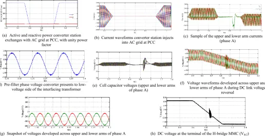
redundant switch states offer new attractive features of interests for modern VSC-HVDC links. For demonstration of some of these features, converter station in Figure 1 is fed from a controlled voltage source with initial dc link voltage of 640kV. At time t=0.6s, the dc link voltage is reversed from 640kV to -640kV, with slope of 4pu/s (based dc link voltage=640kV). In this demonstration, a reference active power is set 800MW at unity power factor, and reduced to zero during the dc link voltage reversal, and then restored to 800MW when the dc link voltage is completely reversed, and simulation results obtained are displayed in Figure 3. Figure 3 (a) shows active and
reactive power converter station exchanging with the ac grid. Figure 3 (b) shows converter station output currents measured at PCC, zoomed around dc link voltage reversal event and active power restoration. Figure 3(c) shows the upper and lower arm currents for phase ‘a’ are well controlled during operation with positive and negative dc link voltages, with limited transients are observed in the regions when the dc link voltage is practically zero. Figure 3 (d) shows a pre-filter phase voltage (va0) FB-MMC presents to the low-voltage side of the
interfacing transformer. The plots for the cell capacitor voltages presented in Figure 3(e) show that the voltages across these cell capacitors are well regulated around 640kV/2130.47kV, independent of the dc link voltage polarity. Furthermore, the plots for the voltages developed across the upper and lower arms displayed in Figure 3 (f) and its snapshot in Figure 3 (g) show that the dc components of the upper and lower arm voltages follow the dc bias of the modulation functions, which are adjusted by the proposed control scheme as previously claimed. Figure 3 (i) presents the dc link voltage (Vdc2)
ac grid (this means that the peak fundamental voltage FB-MMC can generator is no longer coupled to dc link voltage as in HB-MMC and conventional VSCs).
B) Decoupling of cell capacitor voltages from converter DC
link voltage
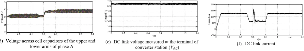
Figure 4 shows selected waveforms that illustrate the usefulness of ‘md’ manipulation for decoupling of the
FB-MMC cell capacitor voltages regulation from the converter dc link voltage. In this illustration, the FB-MMC dc link voltage in Figure 1 is maintained at 640kV and its cell capacitor voltages are initially regulated at 30.48, and at t=0.6s, the cell capacitor reference voltage is increased by 10% (33.52kV). In attempt to minimize any transients from change of energy level of these cell capacitors, the active power converter station exchanges with ac grid is temporary reduced from 800MW to 400MW at
t=0.5s, and then restored to 800MW at t=0.8s, see Figure 4 (a). Observe that the plots for the inverter output phase currents measured at PCC in Figure 4 (b) show no undesirable transients during change of cell capacitor voltage set-point. Figure 4 (c)
shows plots for the upper and lower arm currents, and these plots have exhibited limited transients as the cell capacitor reference voltage is increased from 30.48kV to 33.52kV (this means that the total voltage across each converter arm is increased from 640kV to 704kV). Figure 4 (d) shows that the cell capacitor voltages of the FB-MMC being investigated follow their reference voltage and tightly regulated over the entire simulation period. Observe that the measured input dc voltage (Vdc2) is independent of the cell capacitor voltages, with
the dc link current magnitude remains determined by the active power converter exchanges with the ac grid and input dc link voltage, see Figure 4 (e) and (f). However, the dc link current has shown clear transient when the reference cell capacitor voltage is increased, and then returns to its expected settling point. The results presented in Figure 3 and Figure 4 show that the proposed control scheme is able to decoupling cell capacitor voltage regulation from converter dc link voltage, including during dc link voltage reversal.
(a) Active and reactive power converter station
exchanges with AC grid at PCC, with unity power factor
(b) Current waveforms converter station injects
into AC grid at PCC
(c) Sample of the upper and lower arm currents
(phase A)
(d) Pre-filter phase voltage converter presents to
low-voltage side of the interfacing transformer (e) Cell capacitor voltages (upper and lower arms of phase A)
(f) Voltage waveforms developed across upper and
lower arms of phase A during DC link voltage reversal
(g) Snapshot of voltages developed across upper and lower arms of phase A
when DC link voltage is completely reversed to -640kV
[image:4.612.49.566.291.556.2](h) DC voltage at the terminal of the H-bridge MMC (Vdc2)
Figure 3: Waveforms illustrates closed loop performance of H-bridge MMC during DC link voltage reversal
(a) Active and reactive power converter station
exchanges with AC grid
(b) Current waveforms converter injects into AC
grid at PCC1
(c) Sample of upper and lower arm currents (phase
[image:4.612.47.558.590.682.2](d) Voltage across cell capacitors of the upper and
lower arms of phase A (e) DC link voltage measured at the terminal of converter station (Vdc2)
[image:5.612.47.554.60.145.2](f) DC link current
Figure 4: Waveforms obtained when cell capacitor voltage balancing of the H-bridge MMC HVDC converter is decoupled from the DC link voltage and AC grid voltage
IV.
C
ONCLUSIONSThis paper has explored new operating regions of the FB-MMC that could be exploited to enable HVDC transmission links to ride through DC faults with and without converter blocking, with controlled recharge of the DC link cables after a DC fault is cleared (as demonstrated in [19]. Also, it allows FB-MMC operation with variable DC link voltage ranging from Vdc to –
Vdc (as demonstrated in this paper). The usefulness of the new
operating regions was validated using simulations. The generic nature of the proposed control scheme is demonstrated using simulation of HVDC converter station that employs FB-MMC with 21 cells per arm that uses staircase modulation.
V.
A
CKNOWLEDGMENTThis work was supported by the EPSRC UK Centre for Power Electronics under Grant EP/K035304/1 (Converter Theme Research Programme).
VI.
R
EFERENCES[1] T. Jonsson;, P. Lundberg;, S. Maiti;, and Y. J. Hafner, "Converter Technologies and Functional Requirements for Relaible and Economical HVDC Grid Design," presented at the Cigre2013, Alberta, Canada, Sept, 2013.
[2] R. Marquardt, "Modular Multilevel Converter topologies with DC-Short
circuit current limitation," in Power Electronics and ECCE Asia (ICPE
& ECCE), 2011 IEEE 8th International Conference on, 2011, pp. 1425-1431.
[3] R. Marquardt, "Modular Multilevel Converter: An universal concept for
HVDC-Networks and extended DC-Bus-applications," in Power
Electronics Conference (IPEC), 2010 International, 2010, pp. 502-507. [4] A. Lesnicar and R. Marquardt, "An innovative modular multilevel
converter topology suitable for a wide power range," in Power Tech Conference Proceedings, 2003 IEEE Bologna, 2003, p. 6 pp. Vol.3. [5] Y. Zhang, G. P. Adam, T. C. Lim, S. J. Finney, and B. W. Williams,
"Analysis of modular multilevel converter capacitor voltage balancing based on phase voltage redundant states," Power Electronics, IET, vol. 5, pp. 726-738, 2012.
[6] G. P. Adam, O. Anaya-Lara, G. M. Burt, D. Telford, B. W. Williams, and J. R. McDonald, "Modular multilevel inverter: Pulse width
modulation and capacitor balancing technique," Power Electronics, IET,
vol. 3, pp. 702-715, 2010.
[7] G. P. Adam, K. H. Ahmed, S. J. Finney, and B. W. Williams, "Modular multilevel converter for medium-voltage applications," in Electric Machines & Drives Conference (IEMDC), 2011 IEEE International, 2011, pp. 1013-1018.
[8] O. A. Giddani, G. P. Adam, O. Anaya-Lara, G. Burt, and K. L. Lo, "Control strategies of VSC-HVDC transmission system for wind power integration to meet GB grid code requirements," in Power Electronics Electrical Drives Automation and Motion (SPEEDAM), 2010 International Symposium on, 2010, pp. 385-390.
[9] S. Rohner, S. Bernet, M. Hiller, and R. Sommer, "Analysis and Simulation of a 6 kV, 6 MVA Modular Multilevel Converter," in
Industrial Electronics, 2009. IECON '09. 35th Annual Conference of
IEEE, 2009, pp. 225-230.
[10] B. Li, R. Yang, D. Xu, G. Wang, W. Wang, and D. Xu, "Analysis of the Phase-Shifted Carrier Modulation for Modular Multilevel Converters,"
Power Electronics, IEEE Transactions on, vol. PP, pp. 1-1, 2014. [11] M. Hagiwara and H. Akagi, "Control and Experiment of
Pulsewidth-Modulated Modular Multilevel Converters," Power Electronics, IEEE
Transactions on, vol. 24, pp. 1737-1746, 2009.
[12] T. Qingrui, X. Zheng, and X. Lie, "Reduced Switching-Frequency Modulation and Circulating Current Suppression for Modular Multilevel
Converters," Power Delivery, IEEE Transactions on, vol. 26, pp.
2009-2017, 2011.
[13] T. Qingrui, X. Zheng, and X. Lie, "Reduced switching-frequency modulation and circulating current suppression for modular multilevel
converters," in Transmission and Distribution Conference and
Exposition (T&D), 2012 IEEE PES, 2012, pp. 1-1.
[14] Z. Xin, L. Guangkai, and Z. Chengyong, "Research on submodule capacitance voltage balancing of MMC based on carrier phase shifted
SPWM technique," in Electricity Distribution (CICED), 2010 China
International Conference on, 2010, pp. 1-6.
[15] N. Thitichaiworakorn, M. Hagiwara, and H. Akagi, "Experimental Verification of a Modular Multilevel Cascade Inverter Based on
Double-Star Bridge-Cells (MMCI-DSBC)," Industry Applications, IEEE
Transactions on, vol. PP, pp. 1-1, 2013.
[16] N. Thitichaiworakorn, M. Hagiwara, and H. Akagi, "Experimental verification of a modular multilevel cascade inverter based on
double-star bridge-cells (MMCI-DSBC)," in Energy Conversion Congress and
Exposition (ECCE), 2012 IEEE, 2012, pp. 4196-4202.
[17] H. Akagi, "Classification, Terminology, and Application of the Modular
Multilevel Cascade Converter (MMCC)," Power Electronics, IEEE
Transactions on, vol. 26, pp. 3119-3130, 2011.
[18] B. S. Riar and U. K. Madawala, "Modelling of modular multilevel
converter topology with voltage correcting modules," in Power
Electronics for Distributed Generation Systems (PEDG), 2014 IEEE 5th International Symposium on, 2014, pp. 1-4.
[19] G. Adam and I. Davidson, "Robust and Generic Control of Full-Bridge Modular Multilevel Converter High-Voltage DC Transmission Systems," Power Delivery, IEEE Transactions on, vol. PP, pp. 1-1, 2015. [20] G. P. Adam and B. W. Williams, "Half and Full-Bridge Modular
Multilevel Converter Models forSimulations of Full-Scale HVDC Links
and Multi-terminal DC grids," Emerging and Selected Topics in Power