City, University of London Institutional Repository
Citation
:
Mikulich, V. & Brücker, C. (2013). Flow and motion behavior of particle
suspensions in shear flow over a rough surface. WIT Transactions on Engineering Sciences,
79, pp. 263-272. doi: 10.2495/MPF130221
This is the accepted version of the paper.
This version of the publication may differ from the final published
version.
Permanent repository link:
http://openaccess.city.ac.uk/16769/
Link to published version
:
http://dx.doi.org/10.2495/MPF130221
Copyright and reuse:
City Research Online aims to make research
outputs of City, University of London available to a wider audience.
Copyright and Moral Rights remain with the author(s) and/or copyright
holders. URLs from City Research Online may be freely distributed and
linked to.
Flow and motion behavior of particle
suspensions in shear flow over a rough surface
V. Mikulich, C. Brücker
Institute of Mechanics and Fluid Dynamics, TU Bergakademie Freiberg,
Germany
Abstract
The article discloses the experimental study results of the behavior of a thin layer of low concentrated slurry in a shear flow over a rough surface with a defined structure of the bottom wall. A new ring shear device was built which contains an optically transparent test chamber of which the bottom wall contains arrays of micro-cantilever force sensors simulating a defined surface roughness. It was created by deep-etching of micro-pillars in a silicon wafer. The results of visual observation of the interaction of the suspension with the structured surface during severe deformation are shown. Observation covered the liquid phase motion by micro-PIV, the interaction between the liquid phase and solid particles, the movement of separate particles and their mutual interaction. The contact interactions between particles and micro-pillars are exemplified. The abrupt changes in rotational motion and translational velocity of particles induce mutual collisions and continuous formation and break-up of cluster structures of various types.
Keywords: slurry, shear flow, micro-structured surface, particle interaction, micro-pillars, cantilever-array, force-measurements.
1
Introduction
out in a narrow gap between the process tool and the workplace surface. The complex mechanical behavior of particles in interaction with the walls and multiple contacts with each other in the process gap as well as cluster formation and break-up are not understood sufficiently yet. Experimental study of such systems is very scarce. Hence, detailed analysis of the process parameters with the specific requirement of the surface structures is impossible.
This article presents a new experimental reference-model for processes in gap flows, which is based on microscopic measurement techniques of the forces at particle-wall interaction as well as the flow behavior at the micro scale. The reference model has defined boundary conditions regarding to the roughness and the fracture behavior of the surface which offers unique possibilities for comparison and validation of the numerical simulations.
2
Experimental details
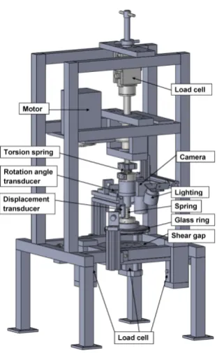
Figure 1: Ring shear apparatus
The narrow test chamber is defined by the outer edges of a glass ring as shown in Fig. 2. The inner and outer diameter of the ring is 90 mm and 110 mm, respectively. The slurry is held in the gap between the upper glass ring and the fixed bottom wall. Shear is imposed by rotation of the upper ring under defined axial load and rotation speed. The bottom wall represents the micro-structured surface we used for the analysis of deformation, damage and wear in industrial silicon processing, see Fig. 3. The surface was created by etching micro-pillars that simulated surface roughness and at the same time were force sensors of the type of micro-cantilever beams according the measurement principle described in Brücker et al [5], Brücker [6]. The deformation and fracture of the micro-pillars during interaction with the particles in the suspension are detected by imaging from top and the side-walls. Brücker et al [5] and Brücker [6] used such an array of flexible micro-hairs in the form of small slender micro-pillars made from an elastomer to measure the wall friction force distribution in turbulent flows. The same principle is applied herein to measure the contact forces during interaction of the particles with the walls.
Figure 2: Schematic of the sample chamber.
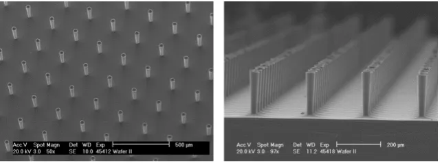
Figure 3: Scanning electron microscope image of a micro-pillar array.
studies using Particle-Image-Velocimetry (PIV), small fluorescent tracer particles in diameter 20 µm are added, too. The method of cross-correlation was applied to double-images in interrogation sizes of 32×32 pixels with a Gaussian peak fitting procedure to detect the displacement vector with subpixel accuracy. The chip sensor size is 1600 × 1200 px. The processing software is based on an inhouse matlab code which allows phase separation between solid and liquid phase. The uncertainty is of order of 0.1 pixel which equates to a velocity uncertainty of 1*10-5m/s. Typical flow speeds are of order of 10-3m/s.
[image:5.595.140.462.380.499.2]a slurry layer thickness of 1.5 mm. The slurry behaviour during shear loading was observed with CCD cameras from two sides of the flow chamber. Light emitting diodes provided illumination and filters ensured epifluorescent imaging. The liquid phase motion and its interaction with large particles ware studied on the small-sized tracer-particles. Bending of the micro-pillars was detected by the reflections at the tip of the cantilever beams. Typical pictures of the flow as seen from top and from the side are given in Fig. 4.
Figure 4: Pictures of the slurry in the shear cell. Left: top view on the slurry showing the reflections of the micro-pillars at the bottom wall as a regular grid (physical size of the image area is 7 × 5.5 mm2). Right: side view demonstrating
the micro-pillars and the glass balls above (physical size is 1.5 × 0.8 mm2).
3
Results and discussion
The optical access into the slurry gap allows the observation of particle behaviour in the suspension, the interaction between the liquid phase and particles, the movement of separate particles, their mutual interaction and the interaction with the micro-structured surface. From bending of the micro-pillars, we can estimate the contact forces by application of equations for a linear elastic Euler beam. The material constants such as Young-modulus of silicon are well described in literature. In addition, fracture of the structures is also a well defined event in the process since the position of fracture and the position of force is prescribed by the system (fracture happens at the micro-pillar foot, force is acting at the micro-pillar tip).
[image:7.595.142.450.149.636.2]
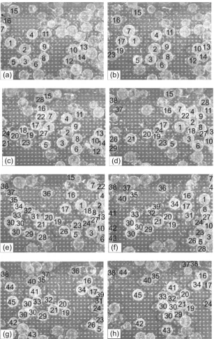
Figure 5: Image sequence showing the particle motion in the suspension under shear load of the slurry (flow is from left to right). The time step between
Due to the velocity gradient, all particles come into rotation, too. Thanks to the uneven coating of the glass balls, we could not only determine the translational motion but also quantify particle rotation in the images. Moving speed and the rotation speed for particles being not in contact with other particles depends on their size and their position in the layer of a sheared suspension.
Translational speed of most of the particles coincides with the local velocity of the liquid phase. For example, the particles #39 (Fig. 5f, 5g) and #28 (Fig. 5e, 5f) which are moving in a layer of liquid closer to the rotating ring move faster in comparison to other particles. The speed of rotation relative to the translational speed of the particles increases when the particles came into contact with structured surfaces. In addition, the direction of movement of the liquid phase has impact on the path of the movement of single particles. As an example it is possible to watch the motion of particle #37 (Fig. 5d, 5e, 5f) and particle #44 (Fig. 5g, 5h) with the liquid phase around a particle #38 which is slower than the others.
In Fig. 5 it is also demonstrated, that at a shear flow in a thin layer, many particles of the suspension, even at relatively low concentrations, cannot move independently. Due to the kinematic restrictions of the test chamber walls, their roughness (microstructures) affects strongly the behavior of particles. It is manifested by abrupt changes in the motion direction and the deceleration of translational and rotary motion of particles. In these cases, we observed a discrepancy between the velocities of the liquid layer and the particles. During contact with other particles, we watched them change their direction of rotation. The changes in rotation direction and the translational velocity of particle induce their mutual collisions and continuous formation and destruction of their aggregate structures of various types. The particles form differently oriented chains and compact structures of different density. These aggregate structures sometimes can remain for longer periods and continue to move as a unit. Moving chains sometimes are destroyed by individual particles which are in contact with the bottom wall.
[image:8.595.141.451.531.617.2]
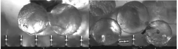
Figure 6: Interaction of particles with the micro-pillar surfaces.
of the small thickness of a layer of sheared suspension rotation of such particles is partially limited. They decelerate typically more often and they tend to attach to the bottom wall and remain at rest. Their rotation is typically more complicated and periodical. In Figure 5e, 5f, 5g, 5h, we can observe the motion of a larger particle agglomerate (glued from three balls) as particle #30.
[image:9.595.223.369.391.554.2]The interaction of particles with the bottom surface is indicated by the abrupt deceleration of movement and the tendency to stop. During the deformation of the suspension, many single particles contacted the structured surface of the chamber, but the event of a fracture of the micro-pillar could not be captured live in the sequence. However, from the flow of broken micro-pillars in the liquid phase we concluded that fracture events were appearing in a regular manner. As soon as a particle remains in contact with a micro-pillar and stops its motion, it prevents the free flow of other trailing particles and leads to structure's formation. Movement of particles #13 and #10 in Fig. 5 is an example of such behavior. After deceleration and coming to rest, subsequent movement of large particles or aggregates then causes high hydrodynamic drag forces and drastically enlarges the contact forces at the micro-pillar. This leads to the fracture of the micro-pillars in a defined manner, Fig. 6.
Fig. 7: Principle of measuring the contact force by elastic bending of the micro-pillars. Note that critical load leads to well defined fracture of the structure at
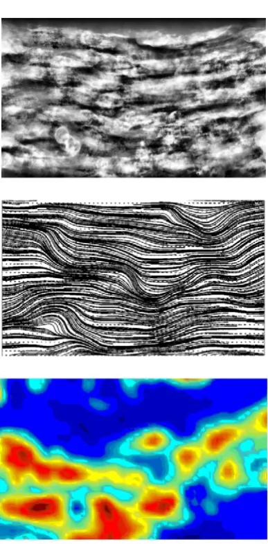
Fig. 8: Representation of the particle and fluid motion statistics: Top: Average of image sequence showing preferred paths of particles and events of particle contacts with the bottom wall. Center: streamlines of the liquid phase showing regions of large disturbances where the flow is forced to swirl around clusters or particles at rest. Bottom: regions of high flucuation energy of fluid motion (color bar from <u^2>/U^2=0.1 in red to 0 in blue). Physical size of image area is is 11.6 × 7 mm2.
the flow of the liquid phase and therefore generates high fluctuations in the flow direction at different positions in the shear cell.
4
Conclusions
A new shear cell has been presented which allows the optical observation of cluster behaviour and contact forces in a suspension. The new mechanical model is well suited for comparison with theoretical studies due to the defined boundary conditions of micro-pillar bending and critical load when a fracture happens. Our visual observations showed that during rotation, contact and structure formation, the flow around the particles create largely different hydrodynamic forces which fluctuate in direction and magnitude. As a consequence flow patterns evolve which show micro-vortices resembling those that occur in locally turbulent flows. The largely fluctuating hydrodynamic drag forces also causes critical loads that lead to fracture of the micro-pillars. These events were documented by the broken micro-pillars that were flowing in the slurry after fracture. The design of the apparatus has a great influence on the test results. In the experimental studies carried out, the characteristic height of the shear cell was about 2-3 average particle diameters. In this case, the mechanical behavior of the suspension is not invariant with respect to the device, depending on its geometry and the roughness of the walls. In our device, the upper wall is allowed to adapt to the internal forces by axial motion against a spring. Therefore, there is volatility of the gap width as a consequence of material deformations in the direction orthogonal to the shear direction. Under such conditions, dilatancy can occur in the suspension. The latter can lead to the short appearance of larger suction pressures in the suspension.
Acknowledgments. The Deutsche Forschungsgemeinschaft (DFG) supported the work under contract BR 1494/20-1.
5
References
[1] Bjerrum, L., & Landva, A., Direct simple shear tests on a norwegian quick clay. Geotechnique , 16(1), pp. 1–20, 1966.
[2] Bishop, A.W., Green G.E., Garga, V.K., Andresen, A., Brown J.D., A new ring-shear apparatus and its application to residual strength. Geotechnique,
21(4), pp. 273–328, 1971.
[3] Bromhead, E. N., A Simple Ring Shear Apparatus. Ground Engineering,
12(5), pp. 40–44, 1979.
[4] Carr, J.F. & Walker, D.M., An Annular Shear Cell for Granular Materials,
Powder Technology,1(6), pp. 369–373, 1968.
[5] Brücker, Ch., Spatz, J., Schröder, W., Feasibility study of wall shear stress imaging using microstructured surfaces with flexible micropillars. Exp. Fluids, 39, pp. 464–474, 2005.
[6] Brücker, Ch., Signature of varicose wavepackets in the viscous sublayer.