Design and manufacture of a bed supported tidal turbine model for
blade and shaft load measurement in turbulent
fl
ow and waves
Gr
egory S. Payne
a,*, Tim Stallard
b, Rodrigo Martinez
a aSchool of Engineering, University of Edinburgh, Edinburgh, EH9 3FB, UKbSchool of Mechanical, Aerospace and Civil Engineering, University of Manchester, Manchester, M13 9PL, UK
a r t i c l e i n f o
Article history:
Received 1 February 2016 Received in revised form 4 January 2017 Accepted 31 January 2017 Available online 3 February 2017
Keywords:
Tidal stream turbine Experimental testing Instrumentation Turbulence loading
a b s t r a c t
Laboratory testing of tidal turbine models is an essential tool to investigate hydrodynamic interactions between turbines and theflow. Such tests can be used to calibrate numerical models and to estimate rotor loading and wake development to inform the design of full scale machines and array layout. The details of the design and manufacturing techniques used to develop a highly instrumented turbine model are presented. The model has a 1.2 m diameter, three bladed horizontal axis rotor and is bottom mounted. Particular attention is given to the instrumentation which can measure streamwise root bending moment for each blade and torque and thrust for the overall rotor. The model is mainly designed to investigate blade and shaft loads due to both turbulence and waves. Initial results from tests in a 2 m deep by 4 m wideflume are also presented.
©2017 The Authors. Published by Elsevier Ltd. This is an open access article under the CC BY license (http://creativecommons.org/licenses/by/4.0/).
1. Introduction
Tidal energy has seen a rapid development over recent years with several developers now conducting offshore trials of full-scale prototypes generating electricity to the grid. These ma-chines are pre-commercial (Technology Readiness Level (TRL) 8) and it is expected that further technological development will reduce cost towards the range required for TRL 9. As part of that process, numerical modelling tools such as Blade Element Mo-mentum (BEM) and Computational Fluid Dynamics (CFD) are widely used for load predictions and wake analysis. However, the interactions between tidal turbines and the water flow are complex and there remain limitations to these numerical methods, particularly concerning methodologies for representing the complexity of turbulent tidal flows, including with waves, and the effect of these flows on loading and wake recovery. Physical testing in laboratory conditions is therefore an essential tool to provide validation data for numerical models and insight into the physical processes of theseflow/turbine interactions to inform improvements to machine design. This paper details the design and manufacture of a turbine developed to study peak
loading on tidal turbines associated withflow, turbulence, waves and impact.
Several prototype tidal stream turbines have now been developed and evaluated at offshore test-centres such as the European Marine Energy Centre (EMEC). The most widely trialled designs comprise a two- or three-bladed horizontal axis turbine with nacelle supported on a rigid bed connected structure (Als-tom/GE, Hammerfest, Atlantis). Prototypes are of the order of 18e24 m diameter, designed for operation in water depths greater than approximately 30 m. Fatigue design of turbines and components is critical and requires accurate prediction of load-cycles through the operating life. Unsteady loading of full-scale turbines is due to complex onset flow with mean velocity and velocity profile varying continuously during the tidal cycle and unsteady onset velocity due to turbulence and free-surface waves. Prediction of peak loads is also required and this may be due to environmental loads or impact with immersed bodies, for which it is crucial to predict the flowfield incident to the rotor plane [5]. For large-scale electricity generation it is ex-pected that farms comprising multiple turbines would be deployed. To predict energy yield from farms, accurate prediction is required of the effect of energy extraction on theflow (Garrett and Cummins [12], of the effect of flow constraint on turbine performance (e.g. due to blockage [27]) and in particular, of development of wakes from isolated turbines and from groups of turbines.
*Corresponding author.
E-mail addresses: gregory.payne@ed.ac.uk (G.S. Payne), Tim.Stallard@ manchester.ac.uk(T. Stallard),R.Martinez@ed.ac.uk(R. Martinez).
Contents lists available atScienceDirect
Renewable Energy
j o u r n a l h o me p a g e : w w w . e l s e v i e r . c o m/ l o ca t e / r e n e n e
http://dx.doi.org/10.1016/j.renene.2017.01.068
A number of laboratory scale studies of tidal stream turbines have been conducted. The motivation for such studies has generally been for acquiring experimental data for validation of numerical models for prediction of either, or both, aspects of turbine perfor-mance or characteristics of turbine wakes. Turbine perforperfor-mance is typically characterised by variation of time-averaged power and thrust coefficient with tip speed ratio. Such data has been reported from experimental studies of several different turbine geometries, including 3-bladed turbines with diameters of 0.8 m[4], 0.7 m[24], 0.6 m[32], 0.28 m[18]and 0.27 m[31]amongst others. Dual rotor horizontal axis turbine systems have also been studied experi-mentally including adjacent 0.5 m diameter turbines on a central spar [16] and 0.82 m diameter contra-rotating concept [6]. For these turbine geometries, thrust and power variation due to waves has been studied, using a towing tank [9,11,19], with waves following aflow with around 3% turbulence[8,13]and with waves opposing a shallowflow with 12% turbulence[10]. Velocity and turbulence of the wake has also been reported, typically from downstream distance defined by the supporting structure
[24,25,31,32]. Blade loads have been measured for a 0.78 m diam-eter turbine subjected to oscillatory motion in a towing tank[23]. Limited datasets have now also been published fromfield trials including blade load variation due to turbulence on the Alstom 500 kW turbine[7]and the power curve of the Alstom/GE 1 MW turbine[20]each deployed at the EMEC site. The power curve of a smaller scale (1.5 m diameter) four bladed turbine has also been measured through field tests in Strangford Lough Narrows (Northern Ireland)[17].
Although a large body of literature reports on experimental testing of tidal turbine models (see previous paragraph), little in-formation on the actual design and manufacturing of turbine models is available (to the notable exception of Bahaj et al.[3]
which, however, is over a decade old).
The present article aims at addressing this issue by providing a comprehensive and detailed description of the design process and of the manufacturing techniques implemented for a labora-tory scale tidal turbine with both blade and shaft instrumenta-tion. The design motivation and requirements arefirst presented (section 2). They are followed by a description of the overall turbine model design (section3). More detail is then given on the rotor design and on the numerical approach taken to estimate blade and rotor loads (section 4). Development of bespoke instrumentation and the process of generator selection are described (sections5 and 6respectively). The main characteris-tics of the system, as measured through tank testing, are then presented (section7). Finally, the appendices provide details on the waterproofing of the model (section A), the manufacturing techniques employed (section B) and discuss further improve-ments to the design (section C).
2. Design requirements
The design was developed to provide experimental measure-ment of rotor thrust and torque and individual blade loads. It was therefore desirable to maximise geometric scale to facilitate incorporation of blade instrumentation. Maximising geometric scale of the rotor is also desirable to minimise the variation of blade performance with Reynolds number. Overall dimensions are sub-ject toflume dimensions and the turbine was designed for nominal flume water depth of 2 m, suitable for large-scale facilities including IFREMER[14]and FloWaveTT[28]with typical test ve-locities of around 0.8 m s1. A bed mounted support structure was considered to represent the majority of prototype turbines, mini-mising disruption to propagating waves and disrupting the wake near bed rather than near surface. In practical terms this
configuration also facilitates measurement of the wake velocity to within a short distance downstream of the rotor plane, allowing analysis of the tip vortex region.
The overall configuration was selected to study peak loading due to waves and turbulence representing operation of a full-scale turbine at low tide water level. For givenflow speed, wave height and period, peak loads would thus occur at low water level due to increased blockage and lower rate of depth decay of wave induced velocities. A depth to diameter ratio of 1.67 and wave conditions providing hub height velocities of up to 30% of the mean velocity were defined. This ratio is consistent with prior reduced scale studies of turbine wakes and loading conducted in a wideflume
[31] with blades designed to produce a thrust curve similar to a generic full-scale turbine. To focus on the effect of environmental conditions on peak loads, blades were designed to represent the radial variation of thrust of the same generic turbine at a particular tip speed ratio. During the design process emphasis was placed on defining a wetted geometry to minimise effort required for devel-opment of computational meshes. To this end, blades were designed for high rigidity to minimise deflection due to peak combination of wave and current loading. The aim was to keep blade tip deflection within 2% of the rotor radius which corre-sponds to a coning angle of 1.15. Both nacelle and structure were also defined by simple cylindrical sections.
3. Overall turbine model design
The ability of the model to provide high quality measurements was considered a key objective and instrumentation was therefore taken into consideration from the start of the overall design pro-cess. Three main features followed on from that design approach:
1. The sensors are configured in a way to measure as directly as possible the physical quantities of interest.
2. As a consequence all force sensors are located‘upstream’ of water seals so that parasitic friction associated with those seals do not affect measurements.
3. Low voltage signals from the sensors are amplified as close as possible from the sensor themselves and the signal cables are sheltered as much as possible from electromagnetic noise to improve the signal to noise ratio of the measurements.
The rotor design, the model instrumentation and the drive system are described in section 4, 5 and 6respectively. Practical aspects of the waterproofing and manufacturing of the turbine as well as the lessons learnt from developing and testing the model are provided in Appendix A, Appendix B and Appendix C
respectively.
An overview of the design is given in Fig. 1which shows a section view of the CAD model of the turbine.
The main characteristics and components of the model are summarised inTable 1. CADfiles providing the outer geometry of the turbine including the blades can be downloaded fromhttp://dx. doi.org/10.7488/ds/1707.
The selected configuration is described from hub downstream to generator. The root of each blade is attached to the hub via a transducer to measure the streamwise root bending moment. These transducers rely on strain gauge bridges whose low voltage signals are amplified by electronic signal processing units housed in a waterproof enclosure located immediately upstream of the hub, in the nose cone of the turbine, hence minimising the length of the low voltage signal cables exposed to external noise. Detail on the root-bending moment sensors is given in section5.2.
compliance between the two parts which could otherwise adversely affect measurements. Signal conditioning units are built into the sensors which output amplified signals (see section5.1for more detail).
The torque and thrust transducer is bolted to a 304 stainless steel shaft with a solid main section of 25.4 mm in diameter. For the first 60 mm (on the side of the transducer) the shaft is hollow to allow the instrumentation cable to go through and exit at 45to connect to the rotor of the slipring. The cable from the slipring stator is routed through the model to exit at the top of the hollow tower via a waterproof connector (shown in white inFig. 1). The shaft is held in place by two spherical bearings (SKF 22206E and 22205E) suitable for the expected thrust load and allowing for potential angular misalignment. Selection was mainly driven by their internal diameter and the load and rotation per minute (rpm) ratings for these bearings are overspecified for the design condi-tions (summarised inTable 1). The two parts housing the bearings on either side of the shaft are rigidly connected by four 14 mm diameter solid 304 stainless steel rods (two of them are visible in magenta in Fig. 1). This ‘cage’ arrangement is stiff and ensures alignment between the two bearing housings while providing ac-cess to the slipring connections when the waterproofing sleeve is removed.
The rotary shaft seals are located just‘downstream’of the tor-que and thrust transducer. Thus, the interior of the housing shown inFig. 1‘on the right’of the seals, which contain the slipring, the shaft coupling and the motor is a dry environment. More details on the shaft seal arrangement can be found in sectionA.1.2.
A motor is used to provide controllable resistance to the rotor motion induced by theflow. The motor shaft is directly connected to the turbine shaft without a gearbox. This approach is typically
described as ‘direct drive’. A Smartflex coupling made by the company Mayr (www.mayr.com) is used to connect the two shafts. This coupling is compact while offering suitable torque rating. The motor is located at the rear of the nacelle with cables exiting at the back to minimise the impact of electro magnetic interference on the instrumentation. More information on the drive system is given in section6.
The non waterproof components of the model (mainly the drive train and the slipring) are protected from water by thin aluminium alloy cylindrical sleeves. Sharp corners and blunt surfaces are covered as much as possible by fairings to avoid disturbing theflow and to facilitate meshing of the geometry when simulated in CFD. They are shown in light purple inFig. 1. These fairings play no structural roles. To ensure precisefitting, manufacture was by 3D printing from ABS plastic.
4. Rotor design
4.1. Design process
The simulation tool used to estimate the rotor performance and design loads was a standard BEM with Spera high axial induction factor correction as described by Hansen[15]. The code was written in Matlab and a given rotor configuration was simulated in about a second on a standard desktop. The blade sections used are based on the NACA 63-8XX series whose drag and lift coefficients used for the BEM simulations can be found in Bahaj et al.[2].
[image:3.595.38.277.72.387.2]Radial variation of streamwise and azimuthal loads on the blade computed by the BEM code were used as input to a structural analysis. Initially, it was desirable to be able to quickly assess a range of rotor designs and so the structural analysis needed to be computationally efficient. Beam theory was used to assess the maximum tip deflection and to carry out vibration analysis. The blades were discretised spanwise in 80 blade elements (seeFig. 2a), each of constant section. The mechanical properties of each section were computed using the software ABAQUS Simulia which then solves the beam equations for the full blade to compute deflection Fig. 1.Section view of the turbine model and its key dimensions.
Table 1
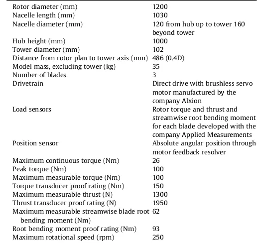
Turbine specifications.
Rotor diameter (mm) 1200 Nacelle length (mm) 1030
Nacelle diameter (mm) 120 from hub up to tower 160 beyond tower
Hub height (mm) 1000 Tower diameter (mm) 102 Distance from rotor plan to tower axis (mm) 486 (0.4D) Model mass, excluding tower (kg) 35 Number of blades 3
Drivetrain Direct drive with brushless servo motor manufactured by the company Alxion
Load sensors Rotor torque and thrust and streamwise root bending moment for each blade developed with the company Applied Measurements Position sensor Absolute angular position through
motor feedback resolver Maximum continuous torque (Nm) 26
Peak torque (Nm) 100 Maximum measurable torque (Nm) 100 Torque transducer proof rating (Nm) 150 Maximum measurable thrust (N) 1300 Thrust transducer proof rating (N) 1950 Maximum measurable streamwise blade root
bending moment (Nm)
[image:3.595.295.553.85.329.2]and vibration modes. ABAQUS Simulia was run in batch mode using Python scripting to integrate the BEM Matlab code with the structural analysis. With this approach, it was possible to carry out the combined BEM and structural assessment of a given rotor design in an automated way.
Once the rotor design had been selected with the method described above, a detailed CAD model of the blades was generated. It was used to carry out a more time consuming three dimensional finite element analysis (FEA) to provide a more in-depth structural analysis taking into account the root attachment feature not rep-resented in the beam model. The loads were once again computed from BEM and input into SolidWorks Simulation. The FEA analysis was used to confirm the blade deflection predicted by beam theory (which was within 6% of the FEA results) and to check that the level of stress throughout the blades is acceptable.Fig. 2b shows the maximum deflection predicted by the FEA analysis. The dimensions offinal blade shape used for the turbine is given inTable 2.
4.2. Detailed blade design
4.2.1. Blade CAD design
[image:4.595.139.471.270.716.2]Using the dimensions fromTable 2a CAD model of the blade was constructed. The shape of each of the ten foil profiles was obtained from the software JavaFoil (developed by Martin Hepperle and available from www.mh-aerotools.de/airfoils/javafoil.htm) which was used to provide the coordinates of 60 points describing each profile. The coordinates were rotated by the twist angles indicated in Table 2. The centre of rotation used is located at a quarter of the chord line from the leading edge. This corresponds approximately to the aerodynamic centre of the foil sections ([1]; Ch. 4). The points were then imported in a CAD software at the appropriate radial location (given inTable 2) with the axis of the blade going through the quarter-chord point of each foil section. The discreet points describing each section were used to generate smooth interpolated curves which were in turn used as support for
an interpolated lofted surface. The blade CAD model was originally constructed with SolidWorks but it was found difficult to build a smooth transition from the circular root attachment to the blade main section. In the end, the MultiSurf/SurfaceWorks (developed by AeroHydro) add-in to SolidWorks was used as it provides better control of lofted surfaces. It should be noted that because of the feature at the blade root necessary to attach it to the hub, the blade section at the very root (r/R¼0.1) is a circle 44 mm in diameter rather than the foil section whose characteristics are given in
Table 2. The blade section then rapidly and smoothly morphs from the circular shape of the root into a foil section so that from r/
R¼0.2 it corresponds exactly to the dimensions given inTable 2. The data of the table were nevertheless used without alteration for the BEM modelling. This approximation was considered acceptable given that the blade root makes a relatively small contribution to torque, thrust, and bending moment.
4.2.2. Blade pitch angle adjustment
Being able to set the pitch angle of turbine blades accurately is important as even small angular errors will affect the angle of attack of the blade profile and hence its performance. It is also key to ensure that the pitch angle is consistent across the three blades as they would otherwise perform differently even if their profiles are identical. Finally, in a scale turbine model used for research and development, it is desirable to be able to accurately modify the blade pitch angle to investigate its impact on performance. The arrangement developed to fastened the blade roots to the hub is shown from two different angles by exploded views inFig. 3.
The square face of the root attachment part (which is also the root bending moment transducer, as detailed in section 5.2) is bolted onto the hub. The pitch angle of the blade with respect to the root attachment part is set by the angular adjustment disc and locating pins. The centring pin goes through the blade, the disc and into the root attachment part and defines the pitch axis of the blade. A combination of two smaller pins, one going through the blade root and the disc and the other going through the root attachment part and the disc locks the pitch angular position. The pins are ground and the locating holes reamed thus providing a tightfit which prevents any angular play. The two small locating pins are as far out from the pitch axis as possible, thus providing a high degree of accuracy in pitch angle positioning. Assuming a machining accuracy of 0.02 mm for the location of the holes and given that the angular locating pins are placed at a radius of 19 mm from the pitch axis, this yields an accuracy of 0.12in pitch angle. Once the pitch angular position has been locked with the pins, the six cap screws shown inFig. 3can be fastened to secure the blade, with no risk of modifying the angle while tightening the screws. If the blades need to be mounted at a different pitch, new discs, with different hole patterns need to be made. However, no
modification is required on the blades and on the root attachment parts as the latter arefitted with kidney slots for the screws to go through. This makes it possible to adjust the angle by±5from the central position.
5. Instrumentation
5.1. Torque and thrust transducer
The torque and thrust transducer was custom made by the company Applied Measurements Ltd (www.appmeas.co.uk). As it is located‘upstream’of shaft seal, and therefore in contact with the surrounding water, it was designed to be waterproof and is made of stainless steel. The specifications for its measurement range were based on the maximum rotor loads predicted by the BEM model, with a safety factor of 2 applied. They are summarised inTable 1. From calibration, the‘interactions’of thrust loads on torque read-ings and of torque loads on thrust readread-ings are respectively within 0.06% and 0.11% of the load ratings.
One of the key bespoke features of this sensor for this applica-tion is the cable routing. In addiapplica-tion to the six cables required to supply power and to output torque and thrust signals, 15 are routed through the body of the transducer to supply power to instruments in the turbine nose and return measured signals. The transducer is fitted with a 19 way connector (model DBPU 104 Z092-139 made by Fischer) on the face bolted to the shaft and with a 16 way connector (model DBEU 104 A086-130 made by Fischer) on the face attached to the hub (seeFig. 1). O-rings arefitted at the interfaces between the transducer and the hub and between the transducer and the shaft. This approach makes it possible to conveniently route cables from the waterproof enclosure in the nose cone to the hollow section of the shaft through a waterproof environment.
5.2. Root bending moment transducer
[image:5.595.34.285.638.742.2]The blade root bending moment transducers are located be-tween the hub and the blades. In addition to their role as a Table 2
Blade dimensions based on NACA 63-8XX profile. r is the local radius, R the overall blade radius (0.6 m), c the chord length and t the thickness. *As explained in more detail in the main text, that section was different in manufactured blade.
r/R r (mm) c/R c (mm) t/c (%) t (mm) twist ()
0.1* 60 0.0483 29 58 16.82 23 0.2 120 0.1117 67 25 16.75 19 0.3 180 0.1109 66.56 23.45 15.61 12.35 0.4 240 0.1045 62.72 21.9 13.73 9.96 0.5 300 0.0988 59.3 20.35 12.07 8.91 0.6 360 0.0932 55.92 18.8 10.51 8 0.7 420 0.0883 52.98 17.25 9.14 7.03 0.8 480 0.0857 51.44 15.7 8.08 6.21 0.9 540 0.083 49.82 14.15 7.05 5.74 0.99 594 0.0733 44 12.6 5.54 5.5
measurement instrument they are also an integral part of the mechanical structure of the turbine and their form factor is tightly constrained to keep the nacelle shape streamlined. As such their design is deeply interwoven with those of the hub and the blade. Small load cells with suitable load ratings, such as the Mini series produced by the company ATI Industrial Automation, are available off the shelf. They offer the advantage of measuring not only bending moment but also loads along the standard 6-axis. Although the load cells themselves would probably be small enough tofit within the nacelle diameter, they would however require special adaptor parts to interface between their standard mounting features and the specific mounting feature of the blades. Moreover, these 6-axis load cells are expensive. It was therefore decided to keep the design of the root bending moment transducer ‘in-house’ and to supply the manufactured flexures to Applied Measurements Ltd for strain gauging, waterproofing and calibration.
The overall arrangement of the root bending momentflexures with the hub and the blades is shown inFig. 4. The square beam section of theflexure is strained gauged on the two faces perpen-dicular to theflow direction to measure the streamwise blade root bending moment. A gallery connects the two instrumented faces with the bottom face of theflexure so that the four cables necessary to operate the strain gauge bridge are routed to come out at the bottom.
The design of the transducer was based on load predictions from BEM. The dimensions of the‘deforming’section of theflexure was first computed using beam theory [30] based solely on the maximum root bending moment in the streamwise direction. A comprehensive CAD model of the complete part was then devel-oped and used as a geometrical input for FEA calculations to investigate strain and stress distributions and tofinalise the shape of theflexure. At this stage root bending moment and resultant force in the streamwise and in the cross-flow directions were taken into account.Fig. 5shows the vertical strain distribution predicted by the FEA on the face of theflexure in tension for thefinal design. The pair of grey inner rectangles shows the planned location for the active section of the strain gauge. The strain distribution is clearly not symmetrical with respect to the vertical axis of the part view. This is to be expected as theflexure also experiences loads in the cross-flow direction. The hole in the upper part of theflexure affect significantly the strain pattern but it can be seen that vertical strain distribution within the active part of the strain gauge varies only within about 9%, which is below the 10% limit recommended to reduce gauge fatigue and variations in transducer creep[22]. The vertical strain predicted over the active gauge section ranges be-tween 750 and 800
m
ε. Given that the recommended maximum strain is between 1000 and 1700m
ε[22]this was thought to provide a sufficient safety factor.To avoid significant hysteresis, it is recommended to keep the stress in theflexure below 30% of the yield strength of the material
[image:6.595.47.290.63.248.2][29]. Theflexures were therefore made of grade 2014 T6 aluminium alloy which has a high yield strength of 415 MPa. The maximum stress predicted by the FEA around the active region of the strain gauge is 54 MPa which corresponds to 13% of the material yield strength, thus providing a good safety factor. 2014 T6 aluminium Fig. 4.Close-up view of the turbine model hub, blades and root bending moment
transducer arrangement (left). Root bending moment transducers on its own with hidden edges partially visible to show the internal galleries for cable routing (right).
[image:6.595.127.482.500.702.2]alloy does not have good corrosion resistance. Theflexures were therefore treated with chromic anodising for corrosion protection.
Fig. 6 shows the transducer completed with their waterproof coating. They are mounted onto the hub of the turbine. The nose waterproof enclosure is open and the strain gauge bridge amplifiers can be seen.
The cantilever beam type of transducer is compact and this is the main reason why it was used in this turbine model. However, with such a transducer geometry, although the strain measured is mainly due to streamwise blade root bending moment, it is also affected by the streamwise resultant shear force on the blade and, to a lesser extent, by the cross-flow loads. The FEA model predicts that the vertical strain in the active region of the gauge when the transducer is loaded by bending moment and resultant force in the streamwise and in the cross-flow directions is 4% higher than when it is loaded by the streamwise bending moment only. This differ-ence was deemed small and it was therefore considered that the strain measurement would provide a good indication of stream-wise blade root bending moment. To check that this assumption held true with the physical transducer, an extensive calibration program was commissioned. The principle of the calibration carried out is summarised byFig. 7.
The base of the transducer was bolted on a vertical reference and the blade was replaced by round bar 500 mm in length. The bar was horizontal and featured four attachment points (shown as black dots inFig. 7) evenly spread over its length to which accurate weight could be attached thus applying a vertical force onto the bar (Fin
[image:7.595.35.281.65.264.2]Fig. 7). The weights ranged from 0 to 125 N and readings from the transducer were taken for each weight at each attachment point thus providing a range of bending moment and shear force combi-nations. This operation wasfirst carried out with the force applied in the streamwise direction.Fig. 8shows the resulting calibration line and the relative error betweenfitted and actual bending moment values. On the graphs, different markers are used for the different lever arm lengths at which force is applied. The relative error is quite significant when the load is applied with a short lever arm (125 mm). Fig. 6. Hub of the turbine model with the root bending moment transducers mounted
[image:7.595.118.474.400.715.2]and the nose waterproof enclosure open.
This makes physical sense since that, in this configuration, the ratio of shear force to bending moment is at its largest and shear force is therefore more likely to have a significant impact on the transducer reading. However, as the length of the lever arm increases to 250 mm and above, the relative error falls below 5%.
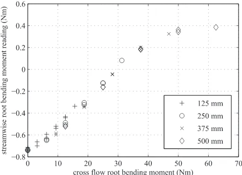
To investigate the ‘interactions’ of cross-flow loading on streamwise readings, the calibration coefficients corresponding to
Fig. 8have been applied the transducer signal when it is loaded purely in the cross-flow direction (corresponding to the bottom right configuration ofFig. 7).Fig. 9shows the outcome in terms of streamwise root bending moment readings as a function of cross-flow loads applied.
The ‘interactions’are overall small compared to the range of bending moment applied. They vary from0.75 to 0.4 Nm with shorter lever arms tending to lead to more‘negative’offsets and longer arms being associated with positive ones.
To establish the overall impact of the streamwise calibration errors combined with‘interactions’on measurements, it is useful to consider streamwise and cross-flow loads and their point of application as predicted by BEM. The point of application of the force varies with TSR because the radial variation of thrust load on the blades varies with TSR. This is shown in Fig. 10 with a free stream velocity is 0.8 m s1. From these graphs it can be seen that in the cross-flow direction the root bending moment does not exceed 10 Nm and that the lever arm length is between 250 and 290 mm. From Fig. 9, this load configuration corresponds to an offset of approximately0.7 Nm. Superimposing this offset to the stream-wise calibration error plotted inFig. 8yields the overall estimated measurement error and is plotted inFig. 11.
For low streamwise root bending moments and short lever arm lengths, the relative error is significant (above 25%). However, ac-cording to the BEM computations (Fig. 10) this load configuration is not expected for tip speed ratio (TSR) values above 3, which is the main operating region of interest for the model. In that TSR range, the streamwise lever arm length varies between 325 and 340 mm and the associated root bending moment is above 20 Nm. This corresponds inFig. 11to an overall relative error below±5% which tends to decrease as root bending moment values increase. It can also be seen fromFig. 11that the relative error is not symmetrical with respect to zero and that their is a slight bias for the transducer to underestimate loads.
Overall the measurement error inferred from calibration are below±5% and they are in line with the FEA predictions over the operating region of interest of the turbine model.
5.3. Slipring and cabling
[image:8.595.314.562.65.312.2]The torque and thrust transducer and the root bending mo-ments sensors are all rotating with the turbine shaft but their Fig. 8.Calibration curve of the transducer (top) and calibration relative error (bottom).
[image:8.595.45.294.67.334.2]The different markers are associated with different lever arm length at which the vertical force is applied.
Fig. 9.Cross-flow load‘interactions’on streamwise readings when the transducer is loaded purely in the cross-flow direction. The different markers are associated with different lever arm length at which the force is applied.
[image:8.595.44.291.529.708.2]cabling needs to be eventually routed through the non moving part of the nacelle. This is achieved using a through bore slipring whose arrangement is shown in Fig. 12. The slipring model used is an AC6349-18 made by the company Moog Components Group and it has 18 circuits.
To make it possible to disassemble the model easily, the cable coming out of the torque and thrust transducer could not be directly soldered to the slipring and a connector was used instead. Given the tight space requirement a high density circular micro connector with 16 ways manufactured by Omnetics was used. (see close-up inFig. 12).
To avoid sensor signals being polluted by electromagnetic noise from the motor/generator or from the environment, signal cables were wherever possible screened cable (with tinned copper braid).
5.4. Data acquisition system
The data acquisition system is based on a National Instruments CompactDAQ USB chassis (cDAQ-9174). A digital I/O module (NI 9401) is used to log the encoder signal generated by the motor (see section6
for more detail). The strain gauge bridge amplifiers used with all sensors provide current signal (4e20 mA) rather than voltage as it is more resilient to electromagnetic interference. A current analogue input module (NI 9203) is therefore used to log these.
To reduce further the impact of electromagnetic interferences onto measured signals, the data acquisition system is enclosed in a
grounded metal cabinet and special care was taken in grounding the screen of the signal cables at their point of entry into the cab-inet. Moreover, opto-isolators are used to electrically decouple the motor encoder signal output by the motor drive from the data acquisition system. The data acquisition cabinet can be seen in
Fig. 13.
6. Drive system
Resistance to the torque induced by theflow onto the rotor is provided by a brushless permanent magnet servo motor. This type of electrical machines was preferred over a generator because a wide range is readily available and because they are highly controllable in speed and in torque with an off the shelf motor drive. Their drawback is that they have poor efficiency when operating as generators but electricity production is not the pur-pose of the model.
The motor torque specifications were inferred from BEM pre-dictions. The other main requirement was the form factor. The hub and nacelle diameter were originally selected to be around 10% of the rotor diameter to minimise influence on the rotor wake. The motor length however is not critical. In the end the diameter requirement had to be relaxed to find a machine with suitable torque rating and consequently, as can be seen inFig. 1, the back of the nacelle has a larger diameter (160 mm) than the front (120 mm).
[image:9.595.35.279.66.228.2]The motor used is a 145ST4M017 model made by the company Alxion (www.alxion.com). It is 145 mm in diameter and 213 mm long (plus shaft). Its continuous torque rating is 26 Nm and the maximum peak torque is 110 Nm. It isfitted with a resolver whose signal is used as an input to the speed control loop but also to re-cord the rotor angular position with the data acquisition system.
Fig. 12 shows the turbine nacelle stripped of its waterproofing sleeves. The motor can be seen on the left.
Given that the motor operates most of the time as a generator and with therefore a poor efficiency, cooling was an important design consideration. Theflow of water around the nacelle provides excellent cooling but it is not directly in contact with the motor body. The motor waterproofing sleeve is therefore made of aluminium alloy which as a good thermal conductivity. The air gap between the motor and the sleeve is kept to minimum (0.5 mm radially) to minimise thermal insulation between the two compo-nents. The sleeve is black anodised to absorb radiated heat better.
The motor is powered by three phase 400 VAC mains supply through a four quadrant drive which is capable of operating the motor as a break/generator and which can dump the generated electricity into a recovery resistor located next to the drive. In Fig. 11.Estimate of the overall relative error in root bending moment measurement as
[image:9.595.114.475.582.720.2]a function of streamwise loads. The different markers are associated with different lever arm length at which the force is applied.
addition to a standard miniature circuit breaker (MCB), the drive supply circuit is alsofitted with a 30 mA residual current device (RCD) to make the system trip in case of accidental current leakage which could arise from water ingress into the motor or its wiring. The RCD is an important safety feature as accidental electrical connection between the motor circuitry and the water of the tank is a potential hazard for operators. The electrical cabinet containing the motor drive and associated supply circuit is shown inFig. 14.
7. Initial tests and measured turbine characteristics
[image:10.595.119.490.66.364.2]Initial measurements of loading and wake due to turbulentflow and waves were carried out at the IFREMER flow recirculating flume in Boulogne-sur-Mer, France. Theflume has a usable section 18 m long, 4 m wide and 2 m deep. It is fitted with a two-dimensional laser Doppler velocimetry (LDV) system mounted on a two-axis automated gantry. More information on the IFREMER Fig. 13.Data acquisition cabinet with the CompactDAQ chassis on the left and power supplies on the right. On the right of the cabinet, signal cables are routed through EMC glands.
[image:10.595.117.487.507.727.2]flow facility can be found in Ref.[14].Fig. 15 shows the turbine being tested with LDV system measuringflow velocity in the tur-bine wake.
Fig. 16shows time series of all the sensors of the model for a test in a meanflow velocity of 0.81 m s1at TSR 6.75 (86 rpm). Sensors were sampled at 256 Hz and are all synchronised as they were all recorded simultaneously over different channels of the same data acquisition system. The measurements shown are a short interval from the overall time series focusing on two full rotations of the rotor. Rotational speed was computed by differ-entiating with respect to time the rotor angular position reported by a digital encoder signal. This explains the‘digital aspect’of the time series of rotational speed. The bottom graph shows the root bending moment of the blades. Each blade is referred to in the legend by its index and by the rotor angular position when the blade is at top dead centre (denoted‘tdc’). It can be seen that the root bending moment time series for each blade is periodic and that the period corresponds to a full rotation of the rotor. The phase shift between the three time series is about a third of the time taken for a full rotor rotation, consistent with 120blade separation. Finally a dip in root bending moment is visible for each blade when close to (but not exactly at) bottom dead
centre (corresponding to a rotor position of 60for blade 1, 300 for blade 2 and 180 for blade 3). This is associated with the shadowing effect of the turbine tower whose centreline is located 0.4 rotor diameter (0.4D or 486 mm) downstream of the rotor plane.
To characterise performance and confirm the operating range of angular speeds, measurements were initially obtained of blade and rotor loading due to turbulentflows with 3% and 12% turbulence intensity (see Germain[14])over a range of tip speed ratios. Mea-surements were subsequently obtained for the low turbulence case with following waves. The measured variation of mean and stan-dard deviation of thrustCTand power CPcoefficient is shown in Fig. 17. These are computed from the experimental measurements as follows:
CT¼1 T 2
r
U02Aand CP¼1Q
u
R 2r
U30A(1)
[image:11.595.37.282.67.448.2]whereTis rotor thrust in N,
r
is water density in kg m3,U0the free stream velocity in m s1,Athe rotor area in m2,Qis the rotor torque Fig. 15.Turbine model being tested at the IFREMERflume with the LDV system on theleft.
in Nm,
u
the rotational speed of the rotor in rads1andRthe rotor radius in m. The coefficients were computed using mean values ofT,Qand
u
. The free stream velocityU0used was the meanflow ve-locity at hub height in the absence of the turbine. For low turbu-lence thrust and power vary with a standard deviation of 3e5% of the mean. For high turbulence mean coefficients are slightly reduced due to the increased range of tip-speed ratio and standarddeviation increases to 10% and 18% for thrust and power respectively.
A bed mounted support structure was employed to minimise disruption to propagating waves and to facilitate measurement of the near-wake region. An example of the wake velocity profiles measured for onset turbulence of 12% is shown inFig. 18. The rate of wake expansion is lower in the vertical direction than horizontal due to closer proximity of free surface (atz/R¼1.67) thanflume wall (aty¼2.33R). This indicates a nearly axisymmetric form as observed for comparable depth to diameter ratio at smaller geo-metric scale[31], although expansion rate may be expected to differ with tip vortex strength (e.g. Ref.[21])and ambient turbulence.
8. Conclusions
Experimental tank testing is an essential tool to investigate the hydrodynamics of tidal turbines. It provides valuable data on rotor loading and wake development which are key to improving turbine design and tidal array layout. Acquisition of quality experimental data requires detailed consideration of instrumentation and system configuration throughout the design and manufacturing process. This study details the development of a highly instrumented tidal turbine model, developed for measurement of peak loading due to combined turbulentflow and waves. The main requirement for the model was therefore a high level of instrumentation. The rotor was designed to produce radial variation of thrust and torque to represent typical operation of a full-scale generic turbine. The model structure, instrumentation and drivetrain are described comprehensively and supplier details for key components are provided. The in-depth information provided about design pro-cesses and manufacturing techniques for this turbine and the instrumentation contribute to the state of the art in turbine model laboratory testing. Key features of the system include bespoke instrumentation for measurement of blade root bending and shaft loading and configuration of instrumentation outboard of the shaft seal to avoid parasitic losses and maximise signal quality. The novel approach to blade-root bendingflexure design enables a compact design facilitating integration within a small diameter hub. This design approach is applicable toflexures for other applications.
The measurement capabilities of the model have been demon-strated through time-series of the signal produced by each of the sensors. Hydrodynamic characteristics of the rotor have been pre-sented in the form of torque and thrust curves derived experi-mentally confirming similar mean performance but elevated variance of loading due to elevated onset turbulence. Initial mea-surements of wake velocity are also provided clearly indicating that depth constraint limits the rate of vertical expansion to lower than the rate of horizontal expansion. The commissioned system thus provides a platform for obtaining highfidelity data on blade, shaft and tower loading due to complex combinations of shear, turbu-lence and waves.
Acknowledgements
This work was supported by the EPSRC via the Marine Challenge grant EP/J010235/1 (X-MED). The authors would like to thank Strathclyde University, Cardiff University, Southampton University and Edinburgh Designs Ltd in the UK and IFREMER in France for providing valuable insight of their experience with designing and making their own turbine models.
[image:12.595.44.293.65.320.2]CADfiles providing the outer geometry of the turbine including Fig. 17.Variation of thrust coefficient (top) and power coefficient (bottom) with tip
speed ratio (b). Mean values (markers) and standard deviation of both coefficients and tip-speed ratio shown for ambientflow with turbulence intensity of 3% (black circle () and range) and 12% (blue square ( ) and range). (For interpretation of the references to colour in thisfigure legend, the reader is referred to the web version of this article.)
Fig. 18.Variation of normalised streamwise velocity along both transverse (Ux(y/R), blue curve) and vertical (Ux(z/R), black curve) axes intersecting the rotor axis.yandz
are the transverse and vertical coordinates respectively. Mean water line (MWL) at
[image:12.595.45.292.493.650.2]the blades as well as the experimental data used to createfigures 16, 17 and 18 can be downloaded fromhttp://dx.doi.org/10.7488/ ds/1707.
Appendices
A. Waterproofing
Some components of the turbine model such as the motor, bearings, the slipring and wiring are only designed to operate in a dry environment. It is therefore a vital requirement to keep some sections of the model and some of the electrical connections watertight.
A.1. Seals
In this model two types of seals are required: static and dy-namic. The former are used to prevent water ingress between parts which need to be moved only for assembly and disassembly pur-poses. The latter are only used to for the shaft, to keep water away while it is rotating.
A.1.1. Static seals. The type of static seals used for this models is o-ring. They are cheap and widely available. Given the benign pres-sures (typically less than 1 bar), temperatures and fluid (water) they have to operate in for this application, standard nitrile buna rubber (NBR) o-ring were used.
O-ring can be either be mounted radially or axially. In the former case, the dimensions of both the o-ring groove and of the radial gap between the two parts to seal are important. With the latter approach, only the groove dimensions (and mainly its depth) matters which makes axial seal more reliable and therefore a preferred option. If radial seals must be used, reliability can be increased by having two of these seals in series.
Larger cord section o-rings offer a larger sealing area and as such tend to be more tolerant to dirt and to small scratches on the surface to seal. On the other hand, they take more space which is not always available when designing a compact model. For the turbine model described herein, o-rings with a cord diameter between 2 and 3 mm have been used. All o-ring seals were greased using Molykote 111 silicon grease made by Dow Corning.
It is highly recommended to use factory made circular o-rings rather than to manually glue o-ring cord to a specific circumfer-ence. The latter approach creates an uneven singularity in the o-ring over which sealing and strength are poor and which can lead to leaks. Factory made circular o-rings are available in a large range of circumferences and can be stretch by up to 3% to fit groove dimensions.
Groove and gap dimensions as well as required surfacefinish and stretch recommendations can be found in numerous o-ring handbooks, often published by o-ring manufacturers (see Ref.[26]
for example).
A.1.2. Dynamic seal. The sealing of the rotating shaft was done using two lip seals made by Tai Tsuang Oil (TTO) similar to the one shown inFig. 19. These are made of Viton and rated to 0.5 bar. Viton, as a material, is over specified for sealing just water at room tempera-ture but these Viton lip seals come with their metal parts either fully covered with Viton (seal frame) or made of stainless steel (lip spring). This is important since the spring is exposed to the high pressure side i.e. the water side.
Two identical lip seals were installed in series along the shaft. This approach provides redundancy and makes it possible to lubricate the seals by having water resistant grease (3752 Almagard made by Lubrication Engineers) between the two lips. This design was inspired by that of shaft seals found in outboard trolling motors.
A.2. Connectors
Water ingress in model circuitry can lead to faults in the instrumentation signals which can be difficult do diagnose as the symptoms are not always those of a clear short-cut. In the power circuit of the motor, water leak can have dramatic consequences for the model and can potentially be dangerous if the voltage is high. Waterproof electrical connectors therefore need to be carefully chosen.
Standard IP68 connectors are not designed for immersion over long durations, especially for depths below 1 m. Rubber moulded marine underwater connectors on the other hand can withstand pressure of tens of bars but tend to be bulky and expensive. Lemo W series connectors have been found to be a suitable compromise between the two above. They feature two o-rings arranged in series which are compressed axially.
A.3. Moisture absorption
Moisture inside sealed containers kept underwater can condense and have severe adverse effects on electrical compo-nents. This issue can easily be addressed byfitting bags of silica gel inside the waterproof housings to absorb moisture. In rotating waterproof compartments or in compartments containing moving parts, the bags should be securely fastened, using elastic band for example. Some types of silica gel change colour when saturated with moisture. It is recommended to use these as they also provide a way to detect moisture ingress.
B. Manufacturing
[image:13.595.308.548.66.272.2]Most metal parts are made of aluminium alloy (grade 6082T6) with some made of stainless steel (grade 304) for extra stiffness and
strength. Conventional and CNC machining were used for most parts.
The turbine tower (seeFigs. 1 and 15) is made of stainless steel 304. The twoflanges werefirst welded on either side of the tube and were then machined to ensure that their respective outside face are well parallel to each other.
The most challenging parts to make were the blades. They were CNC machined from solid metal. The machine used was a three axis CNC mill. The blades were machined in three stages:
1. A bar of rectangular section wasfirst machined to accurate di-mensions. Locations and tapped holes on what was to become the face of the blade root were machined. Holes were also made just beyond what was to become the blade tip.
2. The bar was laid flat on the mill bed and held at a precise location with a special jig using the location holes of the bar. The first side of the blade profile was then machined (seeFig. 20a). 3. The bar wasflipped over and the second side of the blade profile
was machined (seeFig. 20b).
When machining thefirst side, the part is supported all along its span by the material underneath but once it has beenflipped onto its other side, it is only supported underneath at the root and at the tip. This brings about a lack of rigidity which in turns leads to vi-bration during machining. Packing the underneath of the part with expanding polyurethane foam (of the type used for building insu-lation) was found to provide sufficient support to reduce vibrations to an acceptable level. This type of foam comes in different hard-ness and it is recommended to use the hardest possible. To prevent
the foam from sticking to the parts, these were protected by cling film. After machining, the blades were hand polished to remove the ridges left by the ball nose cutter. The completed blades can be seen inFig. 21.
The initial design was to manufacture blades of stainless steel 304 to maximise rigidity. However, due to time constraints, the initial set of blades was manufactured from aluminium alloy 6082T6 which is much faster to machine. According to the FEA analysis, this increases the maximum blade tip deflection from 4.2 mm to 11.5 mm, which is still within 2% of the blade radius and was therefore deemed acceptable. All the aluminium parts were anodised to improve their corrosion resistance. Hard anodising was used except of the parts with tight tolerances. For these, standard anodising, whose growth is smaller, was used.
C. Issues encountered and further improvements
C.1. Rotational speed instability
The initial tests of the turbine model were overall successful but some minor issues were encountered. The most serious one was an instability in the turbine rotational speed. This phenomenon only occurred for specific combinations offlow and rotational speeds. Running the turbine at these rpm values but in the absence offlow did not lead to instability which suggests that the phenomenon has to do with the interaction between hydrodynamics and motor control. In the most severe instances, as the rotor was spinning normally, in the direction induced by theflow, it would abruptly start spinning in the opposite direction for few degrees and then sharply go back to the‘correct’direction for about half a turn before reversing direction for few degrees and so on. The only way to break this cycle was to change either flow or rotational speed. Those jerky oscillations caused significant dynamic loads which the force sensors had not been designed to withstand. The root bending moment transducers were eventually damaged beyond use.
Two steps are currently being taken to address this issue.
The control parameters of the motor drive are to be optimised. The idea is to test the model with all its force sensors replaced by non-instrumented structural dummies. This way the control parameters can be explored comprehensively with no risk of damaging the sensors.
[image:14.595.316.559.125.293.2]Newflexures, to make the root bending moment transducers more robust, have been manufactured out of stainless steel, Fig. 20.CNC machining of turbine blade. (a) shows machining of thefirst side and (b)
[image:14.595.47.289.282.608.2]shows the set-up for machining of the second side with foam packing.3
which will reduce by a factor of about three the level of strain experienced by the stain gauges for the same load. It will also reduce the sensor sensitivity by the same factor but this can be partly compensated by increasing the gain of the strain gauge bridge amplifiers.
C.2. Water ingress detector
Because of time constraints it was not possible tofit the turbine model with water ingress detectors. Although the model did not leak during these initial tests, given the potentially dramatic con-sequences of water ingress, such detectors are being developed. They consist of two strips of thin (about 0.2 mm) stainless steel sheet glued inside and along the length of the water proofing cy-lindrical sleeves. They are glued using double sided tape which ensures electrical insulation between the strips and the sleeves on top of the insulation already provided by the anodising. The smaller the gap between the strips, the better as long as they are not touching. Even small drops of water in that gap will create some electrical conductivity between the two strips. The fact that the strips stretch over the whole length of the sleeve provides an earlier leak detection than if the two contacts were located only at one point.
References
[1] I. Abbot, A. Von Doenhoff, Theory of Wing Sections, Dover Publications, 1959. [2] A. Bahaj, W. Batten, G. McCann, Experimental verifications of numerical pre-dictions for the hydrodynamic performance of horizontal axis marine current turbines, Renew. Energy 32 (15) (2007a) 2479e2490.
[3] A. Bahaj, W. Batten, A. Molland, J. Chaplin, Experimental Investigation into the Hydrodynamics Performance of Marine Current Turbines. Tech. Rep. ISSN 1747-0544, University of Southampton, 2005 sustainable Energy Series Report 3. [4] A. Bahaj, A. Molland, J. Chaplin, W. Batten, Power and thrust measurements of
marine current turbines under various hydrodynamicflow conditions in a cavitation tunnel and a towing tank, Renew. Energy 32 (3) (March 2007b) 407e426.
[5] T. Carlson, B. Watson, J. Elster, A. Copping, M. Jones, M. Watkins, R. Jepsen, K. Metzinger, Assessment of Strike of Adult Killer Whales by an Openhydro Tidal Turbine Blade. Tech. Rep. PNNL-22041, Pacific Northwest National Lab-oratory, 2012.
[6] J.A. Clarke, G. Connor, A.D. Grant, C.M. Johnstone, Design and testing of a contra-rotating tidal current turbine, Proc. Institut. Mech. Eng. Part A J. Power Energy 221 (2) (Jan. 2007) 171e179. URL,http://pia.sagepub.com/lookup/doi/ 10.1243/09576509JPE296.
[7] W. Collier, S. Way, Full-scale validation study of a numerical tool for the prediction of the loading and hydrodynamic performance of axialflow tidal turbines, in: 10th European Wave and Tidal Energy Conference (EWTEC 2013). Aalborg, Danemark, 2013.
[8] T. de Jesus Henriques, S. Tedds, A. Botsari, G. Najafian, T. Hedges, C. Sutcliffe, I. Owen, R. Poole, The effects of wave-current interaction on the performance of a model horizontal axis tidal turbine, Int. J. Mar. Energy 8 (2014) 17e35. [9] D. a. Doman, R.E. Murray, M.J. Pegg, K. Gracie, C.M. Johnstone, T. Nevalainen,
Tow-tank testing of a 1/20th scale horizontal axis tidal turbine with uncer-tainty analysis, Int. J. Mar. Energy 11 (Sep. 2015) 105e119. URL,http:// linkinghub.elsevier.com/retrieve/pii/S2214166915000259.
[10] E. Fernandez-Rodriguez, T. Stallard, P. Stansby, Experimental study of extreme
thrust on a tidal stream rotor due to turbulentflow and with opposing waves, J. Fluids Struct. 51 (December 2015) (2014) 354e361.
[11] P.W. Galloway, L.E. Myers, A.S. Bahaj, Quantifying wave and yaw effects on a scale tidal stream turbine, Renew. Energy 63 (2014) 297e307.
[12] C. Garrett, P. Cummins, The power potential of tidal currents in channels, Proc. R. Soc. A Math. Phys. Eng. Sci. 461 (2060) (2005) 2563e2572.
[13] B. Gaurier, G. Germain, J. Facq, C. Johnstone, A. Grant, a.H. Day, E. Nixon, F. Di Felice, M. Costanzo, Tidal energy”Round Robin”tests comparisons between towing tank and circulating tank results, Int. J. Mar. Energy 12 (2015) (2015) 87e109.
[14] G. Germain, Marine current energy converter tank testing practices, in: 2nd International Conference on Ocean Energy (ICOE 2008). No. October. Brest, France, 2008, pp. 2e7. URL,http://archimer.ifremer.fr/doc/00022/13366/. [15] M.O.L. Hansen, Aerodynamics of Wind Turbines, second ed., Earthscan, 2008. [16] C. Hill, V.S. Neary, B. Gunawan, M. Guala, F. Sotiropoulos, U. S. Department of Energy Reference Model Program RM1 : Experimental Results. Tech. Rep. SAND2014e18783R, Sandia National Laboratories, 2014. URL,http://energy. sandia.gov/download/24671/.
[17] P. Jeffcoate, B. Elsaesser, T. Whittaker, C. Boake, Testing tidal turbines - part 1: steady towing tests vs tidal moored tests, in: Proceedings of the International Conference on Offshore Renewable Energy. Glasgow, UK, 2014.
[18] N. Kolekar, A. Banerjee, Performance characterization and placement of a marine hydrokinetic turbine in a tidal channel under boundary proximity and blockage effects, Appl. Energy 148 (2015) 121e133. URL, http://www. sciencedirect.com/science/article/pii/S0306261915003360.
[19] E.E. Lust, L. Luznik, K.A. Flack, J.M. Walker, M.C. Van Benthem, The influence of surface gravity waves on marine current turbine performance, Int. J. Mar. Energy 3e4 (2013) 27e40.
[20] J. McNaughton, S. Harper, R. Sinclair, B. Sellar, Measuring and modelling the power curve of a commercial-scale tidal turbine, in: Proceedings of 11th European Wave and Tidal Energy Conference. Nantes, France, 2015. [21] S. McTavish, D. Feszty, F. Nitzche, An experimental and computational
assessment of blockage effects on wind turbine wake development, Wind Energy 17 (2014) 1515e1529. URL, http://onlinelibrary.wiley.com/doi/10. 1002/we.1648/full.
[22] Measurements Group, Strain Gage Based Transducers, Their Design and Construction, Measurements Group, Raleigh, USA, 1988.
[23] I. Milne, A. Day, R. Sharma, R. Flay, Blade loads on tidal turbines in planar oscillatoryflow, Ocean Eng. 60 (Mar. 2013) 163e174. URL,http://linkinghub. elsevier.com/retrieve/pii/S0029801812004465.
[24] P. Mycek, B. Gaurier, G. Germain, G. Pinon, E. Rivoalen, Experimental study of the turbulence intensity effects on marine current turbines behaviour. Part I: one single turbine, Renew. Energy 66 (June 2014) 729e746.
[25] L.E. Myers, A.S. Bahaj, Experimental analysis of theflowfield around hori-zontal axis tidal turbines by use of scale mesh disk rotor simulators, Ocean Eng. 37 (2e3) (2010) 218e227.
[26] NewDealSeals, The World's Best o-ring Handbook. Tech. Rep, NewDealSeals, 2015. URL, http://newdealseals.com/en/brochures/14/o-ring-handbook/7/o-ring-technical-handbook.html.
[27] T. Nishino, R.H.J. Willden, Effects of 3-D channel blockage and turbulent wake mixing on the limit of power extraction by tidal turbines, Int. J. Heat Fluid Flow 37 (2012) 123e135, http://dx.doi.org/10.1016/j.ijheatfl uid-flow.2012.05.002. URL.
[28] D.R. Noble, T. Davey, H.C.M. Smith, P. Kaklis, A. Robinson, T. Bruce, Charac-terisation of spatial variation in currents generated in the FloWave ocean energy research facility, in: 11th European Wave and Tidal Energy Confer-ence. Nantes, France, 2015.
[29] C.C. Perry, H.R. Lissner, The Strain Gage Primer, McGraw-Hill, 1955. [30] R. Roark, W. Young, Roark's Formulas for Stress and Strain, McGraw-Hill,
1989.
[31] T. Stallard, T. Feng, P. Stansby, Experimental study of the mean wake of a tidal stream rotor in a shallow turbulentflow, J. Fluids Struct. 54 (2015) 235e246. [32] S.C. Tedds, I. Owen, R.J. Poole, Near-wake characteristics of a model horizontal