UNIVERSITI TEKNIKAL MALAYSIA MELAKA
A DEVELOPMENT OF FIBRE OPTIC SENSOR FOR
DETECTING ALCOHOL (ETHANOL) LEVEL IN PERFUME
This report is submitted in accordance with the requirement of Universiti Teknikal Malaysia Melaka (UTeM) for the Bachelor of Electronic Engineering Technology
(Telecommunications) with Honours.
By
MUHAMAD ANWAR BIN MD KURDI B071310063
900219-01-6757
UNIVERSITI TEKNIKAL MALAYSIA MELAKA
BORANG PENGESAHAN STATUS LAPORAN PROJEK SARJANA MUDA
TAJUK: A Development of Fiber Optic Sensor For Detecting Alcohol Level In Perfume (Ethanol)
SESI PENGAJIAN: 2016/17 Semester 1
Saya MUHAMAD ANWAR BIN MD KURDI
mengaku membenarkan Laporan PSM ini disimpan di Perpustakaan Universiti Teknikal Malaysia Melaka (UTeM) dengan syarat-syarat kegunaan seperti berikut:
1. Laporan PSM adalah hak milik Universiti Teknikal Malaysia Melaka dan penulis. 2. Perpustakaan Universiti Teknikal Malaysia Melaka dibenarkan membuat salinan
untuk tujuan pengajian sahaja dengan izin penulis.
3. Perpustakaan dibenarkan membuat salinan laporan PSM ini sebagai bahan pertukaran antara institusi pengajian tinggi.
4. **Sila tandakan ( ) SULIT
TERHAD
TIDAK TERHAD
(Mengandungi maklumat yang berdarjah keselamatan atau kepentingan Malaysia sebagaimana yang termaktub dalam AKTA RAHSIA RASMI 1972)
(Mengandungi maklumat TERHAD yang telah ditentukan oleh organisasi/badan di mana penyelidikan dijalankan)
_______________________
Alamat Tetap:
No.23, Jalan Dedap 37,
Taman Johor Jaya,
81100 Johor Bahru, Johor
Tarikh: ________________________
Disahkan oleh:
_______________________
Cop Rasmi:
Tarikh: _______________________
iv DECLARATION
I hereby, declared this report entitled “Fiber Optic Sensor for Sodium Chloride Concentration” is the results of my own research except as cited in references.
Signature :………
Name : MUHAMAD ANWAR BIN MD KURDI
v APPROVAL
This report is submitted to the Faculty of Engineering Technology of UTeM as a partial fulfillment of the requirements for the degree of Bachelor of Engineering Technology (Telecommunication) with Honours. The member of the supervisory is as follow:
vi
ABSTRAK
“Penghasilan pengesan gentian optik untuk mengesan tahap alkohol (ethanol) dalam
minyak wangi” adalah dicipta untuk mengesan sukatan alkohol di dalam minyak wangi.
vii ABSTRACT
viii DEDICATION
ix ACKNOWLEDGEMENT
I would like to thank our at Universiti Teknikal Malaysia Melaka lecturers especially my project supervisor Mr. Md Ashadi Bin Md Johari who really helped me a lot throughout finishing my project. They don’t hesitate to teach me whenever I need help or support.
I also would like to thank my friends and my classmates who really help by giving advice and sharing information in finishing my project.
x
TABLE OF CONTENT
Declaration iv
Approval v
Abstrak vi
Abstract vii
Dedication viii
Acknowlegement ix
Table of Content x
List of Tables xiv
List of Figures xv
CHAPTER 1: INTRODUCTION 1
1.0 Background 1
1.1 Problem Statement 1
1.2 Objective 2
1.3 Limitation 2
1.4 Scope 3
CHAPTER 2: LITERATURE REVIEW 4
2.0 Inroduction 4
2.1 Fibre Optic 4
2.1.1 Principle of operation 6
2.1.2 Benefits of Fiber Optics 6
2.1.3 Fiber optic sensor 10
xi
2.2.1 Extrinsic Sensors 14
2.2.2 Intrinsic Sensors 16
2.2.3 Optical methods to study and control the brain 17 2.2.4 Fiber optic hydrogen gas sensor utilizing surface 18
plasmon resonance and native defects of zinc oxide by palladium
2.2.5 Enhancing thermal reliability of fiber-optic sensors 19 for bio-inspired applications at ultra-high temperatures
2.2.6 Optimized Tapered Optical Fiber for Ethanol 20 Concentration Sensing
2.2.7 Refractometric optical fiber sensor for measurement 20 of ethanol concentration in ethanol-gasoline blend
2.2.8 Application of an Optical Fiber Sensor on the 21 Determination of Sucrose and Ethanol Concentrations
in Process Streams and Effluents of Sugarcane Bioethanol Industry
2.3 Ethanol 21
CHAPTER 3: METHODOLOGY 23
3.0 Introduction 23
3.1 Flow Chart 23
3.1.1 Proposal and Selection of Title 25
3.1.2 Literature Review 25
3.1.3 Make a Research 25
3.1.4 Fiber Optic Sensor Development 26
3.1.5 Experiment Process 30
3.1.6 Fibre Optic Sensor Testing 30
3.1.7 Hardware and Eqiupment 30
3.1.8 Collect The Data 33
xii
3.2 Report writing 34
CHAPTER 4: RESULT AND DISCUSSION 35
4.0 Introduction 35
4.1 Project setup 35
4.2 Result and Discussion 36
4.2.1 Light Source 850 36
4.2.2 Light Source 1300 40
4.2.3 Light Source 1310 44
4.2.4 Light Source 1550 48
4.3 Discussion 51
4.3.1 Data Analyze Base On Light source 850nm 52 on four type of perfume.
4.3.2 Data Analyze Base On Light source 1300nm 53 on four type of perfume.
4.3.3 Data Analyze Base On Light source 1310nm 54 on four type of perfume.
4.3.4 Data Analyze Base On Light source 1550nm 55 on four type of perfume.
4.4 Summary for the best selected light source for each state 56 based on sensitivity.
CHAPTER 5: CONCLUSION AND FUTURE WORK 58
5.0 Introduction 58
5.1 Chapter 1 58
5.2 Chapter 2 59
5.3 Chapter 3 60
5.4 Chapter 4 61
xiii
REFERENCES 63
xiv
LIST OF TABLES
4.1 Light Source 850 36
4.2 Light source 1300 40
4.3 Light Source 1310 44
4.4 Light Source 1550 48
xv
LIST OF FIGURES
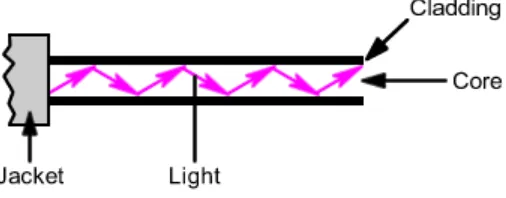
2.1 Light rays incident on the core-cladding interface at the angle 5 greater than the critical angle and trapped inside the fibre core
2.2 Basic fiber optic link 6
2.3 The optical power meter 12
2.4 Extrinsic and intrinsic types of fibre optic sensors 17
3.1 Project Flowchart 24
3.2 Stripping process 26
3.3 Cutting process 26
3.4 Dust removal process 27
3.5 Splicing process 27
3.6 Power loss test process 27
3.7 Perfume 28
3.8 Four type of perfume used in this experiment 28 3.9 The position of fiber optic sensor inside the perfume during experiment 29
3.10 Optical Spectrum Analyzer 30
3.11 Amplifier Spontaneous Emission 31
3.12 Single Mode Fiber Optic 31
3.13 Pigtail cable 32
3.14 Four Type of Perfume 32
3.15 Fusion Splicer 33
4.1 Schematic Diagram of the Fibre Optic Sensor for alcohol detection 36 in perfume
4.2 Graph for all perfume type at light source 850nm 37
4.3 Graph of brand A perfume 38
4.4 Graph of brand B perfume 38
4.5 Graph of brand C perfume 39
xvi 4.7 Graph for all perfume type at light source 1300nm 41
4.8 Graph of brand A perfume 41
4.9 Graph of brand B perfume 42
4.10 Graph of brand C perfume 43
4.11 Graph of brand D perfume 43
4.12 Graph for all perfume type at light source 1310nm 45
4.13 Graph of brand A perfume 45
4.14 Graph of brand B perfume 46
4.15 Graph of brand C perfume 47
4.16 Graph of brand D perfume 47
4.17 Graph for all perfume type at light source 1550nm 49
4.18 Graph of brand A perfume 49
4.19 Graph of brand B perfume 50
4.20 Graph of brand C perfume 50
1
CHAPTER 1
INTRODUCTION
1.0 Background
A fiber optic sensor is a sensor that uses optical fiber either as the sensing element, or as a means of relaying signals from a remote sensor to the electronics that process the signals. Fibers have many uses in remote sensing. Depending on the application, fiber may be used because of its small size, or because no electrical power is needed at the remote location, or because many sensors can be multiplexed along the length of a fiber by using light wavelength shift for each sensor, or by sensing the time delay as light passes along the fiber through each sensor. Time delay can be determined using a device such as an optical time-domain reflectometer and wavelength shift can be calculated using an instrument implementing optical frequency domain reflectometry.
Fiber optic sensors are also immune to electromagnetic interference, and do not conduct electricity so they can be used in places where there is high voltage electricity or flammable material such as jet fuel. Fiber optic sensors can be designed to withstand high temperatures as well.
1.1 Problem Statement
2 measurement and analyze a chemical substance. For example, to obtain a blood sample in medical laboratory, an accurate and precise acetone concentration technique was used.
In general, the chemical sensors are classified into three parts which is gas, liquid and solid particle. The design of chemical sensor is required appreciation of the needed degree of quantitative reliability.
An electrochemical has been introduced to determine the chemical concentration. For example the acetone (alcohol) rate in perfume. Many perfume products in marker claim that the their product is free alcohol. So that this fiber optic sensor was developed to detect the concentration of acetone in perfume. A few type of perfume will be used as research material.
1.2 Objective
The objective of this project is:
i. To study fiber optic sensor operation
ii. To develop fiber optic sensors for detecting alcohol from different brand iii. To analyze the performance of fiber optic
1.3 Limitation
3 1.4 Scope
4
CHAPTER 2
LITERATURE REVIEW
2.0 Inroduction
This chapter will provide the review of previuos research that is related to this final year project. There are previous researches understanding on the fibre optic sensor, technique used in fibre optic sensor, the role of acetone in the diabetic ketoacidosis, acetone in industrial usage, and the current acetone sensor.
2.1 Fibre Optic
5 Optical fibers typically include a transparent core surrounded by a transparent cladding material with a lower index of refraction. Light is kept in the core by the phenomenon of total internal reflection which causes the fiber to act as a waveguide. Fibers that support many propagation paths or transverse modes are called multi-mode fibers (MMF), while those that support a single mode are called single-mode fibers (SMF). Multi-mode fibers generally have a wider core diameter and are used for short-distance communication links and for applications where high power must be transmitted.[citation needed] Single-mode fibers are used for most communication links longer than 1,000 meters (3,300 ft).
[image:20.612.204.457.502.601.2]An important aspect of a fiber optic communication is that of extension of the fiber optic cables such that the losses brought about by joining two different cables is kept to a minimum. Joining lengths of optical fiber often proves to be more complex than joining electrical wire or cable and involves careful cleaving of the fibers, perfect alignment of the fiber cores, and the splicing of these aligned fiber cores. For applications that demand a permanent connection a mechanical splice which holds the ends of the fibers together mechanically could be used or a fusion splice that uses heat to fuse the ends of the fibers together could be used. Temporary or semi-permanent connections are made by means of specialized optical fiber connectors.The field of applied science and engineering concerned with the design and application of optical fibers is known as fiber optics
6 Figure 2.2: Basic fiber optic link
2.1.1 Principle of operation
An optical fiber is a cylindrical dielectric waveguide (nonconducting waveguide) that transmits light along its axis, by the process of total internal reflection. The fiber consists of a core surrounded by a cladding layer, both of which are made of dielectric materials. To confine the optical signal in the core, the refractive index of the core must be greater than that of the cladding. The boundary between the core and cladding may either be abrupt, in step-index fiber, or gradual, in graded-index fiber.
2.1.2 Benefits of Fiber Optics
Fiber optic communication systems have many advantages over copper wire-based communication systems. These advantages include:
1. Long-distance signal transmission
7 Since then, the technology has advanced with tremendous rapidity. By 1985 glass fibers were routinely produced with extremely low losses (< 0.2 dB/km). Voice-grade copper systems require in-line signal regeneration every one to two kilometers. In contrast, it is not unusual for communications signals in fiber optic systems to travel over 100 kilometers (km), or about 62 miles, without signal amplification of regeneration.
2. Large bandwidth, light weight, and small diameter
Today’s applications require an ever-increasing amount of bandwidth. Consequently, it is important to consider the space constraints of many end users. It is commonplace to install new cabling within existing duct systems or conduit. The relatively small diameter and light weight of optical cable make such installations easy and practical, saving valuable conduit space in these environments.
3. Nonconductive
Another advantage of optical fibers is their dielectric nature. Since optical fiber has no metallic components, it can be installed in areas with electromagnetic interference (EMI), including radio frequency interference (RFI). Areas with high EMI include utility lines, power-carrying lines, and railroad tracks. All-dielectric cables are also ideal for areas of high lightning-strike incidence.
4. Immunity to Electromagnetic Interference
8 across the conductor. Fiber optics are immune to this EMI since signals are transmitted as light instead of current. Thus, they can carry signals through places where EMI would block transmission.
5. Data Security
Magnetic fields and current induction work in two ways. They don't just generate noise in signal carrying conductors; they also let the information on the conductor to be leaked out. Fluctuations in the induced magnetic field outside a conductor carry the same information as the current passing through the conductor. Shielding the wire, as in coaxial cables can reduce the problem, but sometimes shielding can allow enough signal leak to allow tapping, which is exactly what we wouldn't want.
There are no radiated magnetic fields around optical fibers; the electromagnetic fields are confined within the fiber. That makes it impossible to tap the signal being transmitted through a fiber without cutting into the fiber. Since fiber optics do not radiate electromagnetic energy, emissions cannot be intercepted and physically tapping the fiber takes great skill to do undetected. Thus, the fiber is the most secure medium available for carrying sensitive data.
6. Non Conductive Cables
Metal cables can encounter other signal transmission problems because of subtle variations in electrical potential. Electronic designers assume that ground is a uniform potential. That is reasonable if ground is a single metal chassis, and it's not too bad if ground is a good conductor that extends through a small building. However, the nominal ground potential can differ by several volts if cables run between different buildings or sometimes even different parts of the same building.
9 Electric utilities have the biggest problems because their switching stations and power plants may have large potential differences.
A serious concern with outdoor cables in certain computer networks is that they can be hit by lightning, causing destruction to wires and other cables that are involved in the network. Certain computer companies are aware of this problem and trying to solve it by having protective devices for wire circuits to block current and voltage surges.
Any conductive cables can carry power surges or ground loops. Fiber optic cables can be made non-conductive by avoiding metal in their design. These kinds of cables are economical and standard for many indoor applications. Outdoor versions are more expensive since they require special strength members, but they can still be valuable in eliminating ground loops and protecting electronic equipment from surge damage.
7. Eliminating Spark Hazards
In some cases, transmitting signals electrically can be extremely dangerous. Most electric potentials create small sparks. The sparks ordinarily pose no danger, but can be really bad in a chemical plant or oil refinery where the air is contaminated with potentially explosive vapors. One tiny spark can create a big explosion. potential spark hazards seriously hinder data and communication in such facilities. Fiber optic cables do not produce sparks since they do not carry current.
8. Ease of Installation