THE DESIGN OF A TWO-LEVEL SOLID-STATE MASER
Colin Kydd Campbell
A Thesis Submitted for the Degree of PhD at the
University of St Andrews
1960
Full metadata for this item is available in St Andrews Research Repository
at:
http://research-repository.st-andrews.ac.uk/
Please use this identifier to cite or link to this item: http://hdl.handle.net/10023/14789
ProQuest Number: 10166667
All rights reserved
INFORMATION TO ALL USERS
The qua lity of this reproduction is d e p e n d e n t upon the qua lity of the copy subm itted.
In the unlikely e v e n t that the author did not send a c o m p le te m anuscript and there are missing pages, these will be noted. Also, if m aterial had to be rem oved,
a n o te will in d ica te the deletion.
uest
ProQuest 10166667
Published by ProQuest LLO (2017). C o pyright of the Dissertation is held by the Author.
All rights reserved.
This work is protected against unauthorized copying under Title 17, United States C o d e M icroform Edition © ProQuest LLO.
ProQuest LLO.
789 East Eisenhower Parkway P.Q. Box 1346
----, V y
IBS8:&G3f CW TlfQ.CKGMRBl l3X30LJLl)«*Sy]&AL93a 3%&j3ISIS
■ k Theala
praaonted h>y
GollnK# 0%mp1)allv<B^8o,# B#M##
‘ “Un4ira3?sity • of- 8t* Andrava *
in applloation fose the Dagraa
of Doctor of PhiloBOpby*
.V
CERTIï’IOATf’ .Ui
I certify that Colin lîQrdd Oainpball, B*Sc* # 8 '* M-#I#R»B#» has.-apcnt nine terms as a- research student
in the Physical Laboratory of the United College of the University of St. Andrews# that he- has fulfilled
the conditions of Ordinance Ho# 16 of the University Court of St.- - AndrewB' and that he • is qualif ied to submit the accompanying-thesis in application for the degree of. Doctor of Philosophy#
0AmE;R
I served in the Royal Corps of Signals and-the Biplomatio Wireless Se-rvioe-from-1944_^..«^ 1948 before matriculation’in the University• of at# Andrews^where
I followed a course leading to graduation in 1968 in Electrical Engineering# • ■ ... — •
-' I studied at - the Massachusetts institute -' of Technology in- 1961-with the aid of a-Gaird Travel - ‘ arant# and again at that institute in 196B and 1963 on the Massachusetts Oolf Association ‘Scholarship# ^ -and there l was awarded the-SiM#-Degree-in* •Electrical Engineering in 1965 and elected to Associate
Memhershrp of Srgma- JCi.#- “■ ■ * - * • ... ,
I was an electronics design engineer until October 1967 Whien 1 was admitted by the Benatus Aoademicus as a research student and began the work
AOKHOWIEDOmETS
I Should like to œpxess my sincere- thanks- to
Professor J . 3 T # A l l e n , , for suggesting the topic and for encouragement throughout Dr# D#Bijl,E«R#B#10# for his supervision and for
' ' ' - his most helpful advice
Royal Haval Scientific for a research and equipment Service ■ - - -grant--' - ... Dr# DfOshome for many stimulating convert
- ' sat ions '
Mr# J#Garrard • for help with, the photographs
Mr. T.MarBhâli;Mr#Ô#Bûn8ire, ^on^the*eauiment°*'^ Mr. i'.Akerbausa, Mr, B.Plrle... . ” ? ®, , Mr# B.Mitohall for the plentiful supply of
' liquid helium .. Mr# E.Gaims for his generous assistance
with components
and to the Research .Office rs, at Harwell, Dounreay#
TABLE 0? COHTEHTS
\ 'A
Bec.Ho. page
1 XITEOPUOTIOl . . 1
1.1 The Maser * , . 1
l.B Scope of Thesis # * . 4
2 BTIMÜIATED A m SPmTAmOUB EmBBIOH OF RAOIATIOH. 6
2.1 BiBotein Transitional Frohahilitles • - * 6
2.2 The Emissive; Üondition # . . 8
2.5 QuantmrMeohahioâl Treatment'of Transition
Probabilities . # . 9
5 RmSOHAHOE AHD miAXATIOH PE0OE8Π8 IB PARA-^
MAcœTXO-aOLlBB; ~ Introduction . . 14 3.1 Spin Hamiltonian ' * * . .... • 14 3.2 Paramagnetic Resonance *. . . 16 3.3 Spin-^Làttioe and Bpin-**Spin *Heleos;ation Processes • 17 3.4 Saturation* > ... # . , 20 3. 5 Power Plow .between the Param^net ic Solid
and the Radiation Field ♦ . 21
3è6 The Bloch.Formulation * « i . 24
4 QIRGUIT mXATXOHSHIPS- FOR A- PARAMAGHETIG SOLID/ IN A —
MICROWAVE mm>XOH GAVXTY RESOmTOR
... introduction . « 29
4.1 Resonant Gavity factor • • . 29 4.2 Effect of. a Paramagnetic Solid in the Cavity » 31 4.3 Conditions for Regenerative and Bupéar- '
regenerative Maser Action . . 33, 4.4 Gain-Bandwidth product . , # 3 5
5 XHVERSI0H CRITERIA AHD OHOICE OF PARmAOHETIC
CRYSTALS — Introduction . . 37
5.1 Inversion Techniques . . . 37
[image:9.615.83.594.69.686.2],1
I
i-'-3ee*H0»
6
6 » 1
6,'la
S r fl'b -6,lo
6 v 2 • '
6>Sa
8 , 8 b
6,'2c
D190EIETI0W-0P TBM AFEABàTüS — Introduction
6 , 3
6v4 ■ 6,4a 6# 4b 6»4o 6,4d 6.5 7.1' 7.2 7.3
KiorowftT'a C ircuit ïy
Xninit ;Ç;irôuit--'- ■Ref 1;! oii piri-O i rouit .Monitor Ml'rouit
The 'Qryobtat ....
O-laOB, Bbwara-;- ■ ... Cfybbtat
Conètruotion-#ilnWall Wave &uido lieooïiaat Oavity Design The Màghet System
Blootfohi'Cs
Kiystron Power Supplies ■Aiapliflàr ■
Pulse SirOuit Power -PulOe Sifoùit Deàigh High»Prequenoy Alternator # « * # * ? # # # « # ♦ * * » ♦ * # f # # * f # ♦
O m m T I O H A H p introduction .
Oryàctat'-Fêrfo’Wkhcé/ - - -, ■* 8p#tromete#^:
Sdhaltlvity-JULii ^ gnment ■•FtobedurlA for .... at0ady?8tate Rèàonanca .Ab60%tl'0h ËxpéViwçhtm '. ' '
Dlmmohd Spoclmené '## -• Steady^Sàata- Eè aonanc©
mmomnrn ' . ’
MgO 0'%y#t&l8' #4# ■ steady -State-Eésonaiicç . . ' Fhçhèmena^ ' -■ ^ . ;... . : ^ , M^f'è^ataia «•'^Tfaneieht-BeaOxiaho© Bhehomena ' , Oiystafa ## -Freilminary I'hrerslon, 6%poriments InVeWion - Exp#?*###-''With the
'TË . 102 ' - -Beeohatdr- : *' * ' * •
7f8a Ampllfie#tioh With IlgO at 143% *
7 #8b O#llldtlon ' w i t h 1 ^ 3 % ' # #
7# 8c Saturation wlth%#lamdnd at 1.3% ; # 7#8d Eeeonance Bxperiiaent with phoephoroue#
Doped silicon . . #
8 GOH0LU8IOH8 AND ABOOMMmimATIOHS 7.4 7.5 7»$ 7é7 7.8 page 48 4$ 54 5 2 5 9 72 77 7 9 79 9 0 9@ 95 95 9 5 114 134 156
A p m m i x A m m E m o m s
LIST OP ILLUSTRATIONS
Fig.Ho# Pag#
1 Susceptibility Opmppnents as Function \ . s
of Saturation # # graph 26
2 Maser Electronics Layout # « <5 ji ^ » . & 4 A 4,.photo 40
3 Microwave Circuit , * schematic 5i
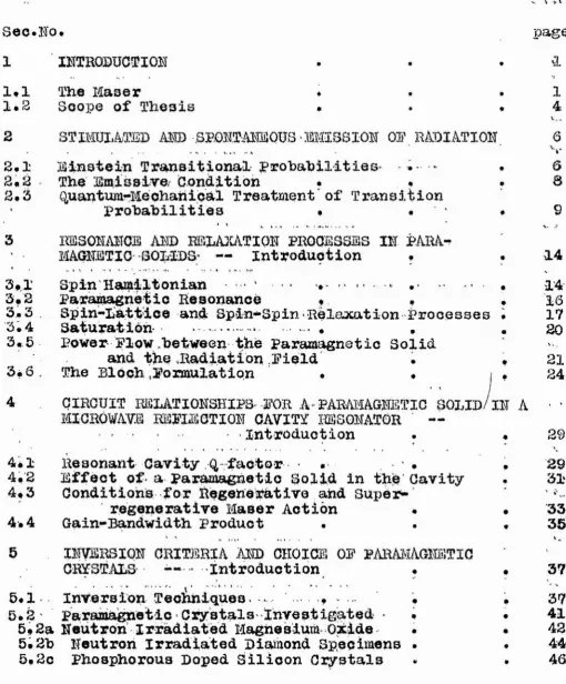
' 4 Màghet ■cryostat . 'photo 6.5
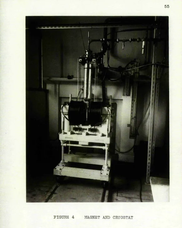
' 5 Magnet and Microwave System * M- ,t t » (t 5Ô
6 Cryostat # * schematic .57
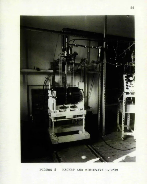
7 TElll and TE102 Cavity Resonators photo 63 à MgO Resonance Line with Two Satellites it 71
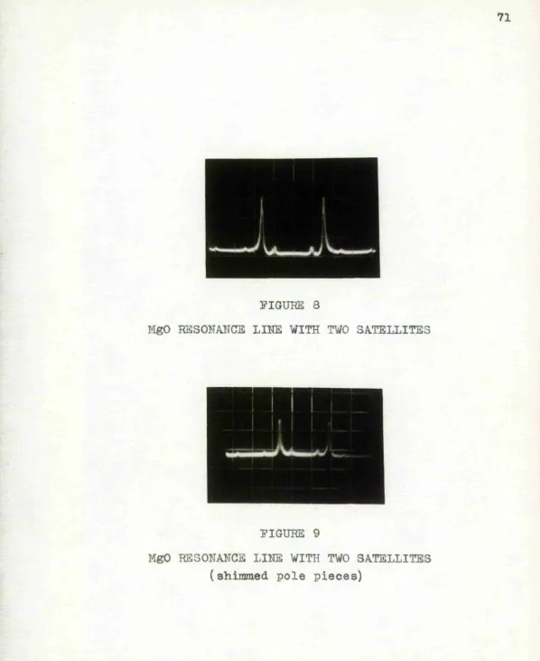
, 9 MgO Resonance Li^e with Two Satellites
, ( shimmed pole, pieces) • . . . . * 71
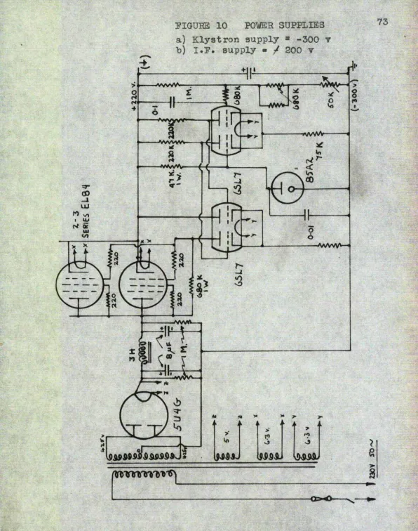
10 Power Supplies • Qoheraatio 73
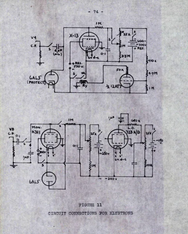
11 Circuit Odhheqtions for Klystrons $ u 74
12 X -Î3 Klystron Power Supply # ♦ ft 75
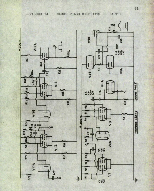
13 Pulse Circuit Power Supply' . # ft 80 14 Maser Pulse 0Ircuitly part 1 ^ # (t 81 16
[iG
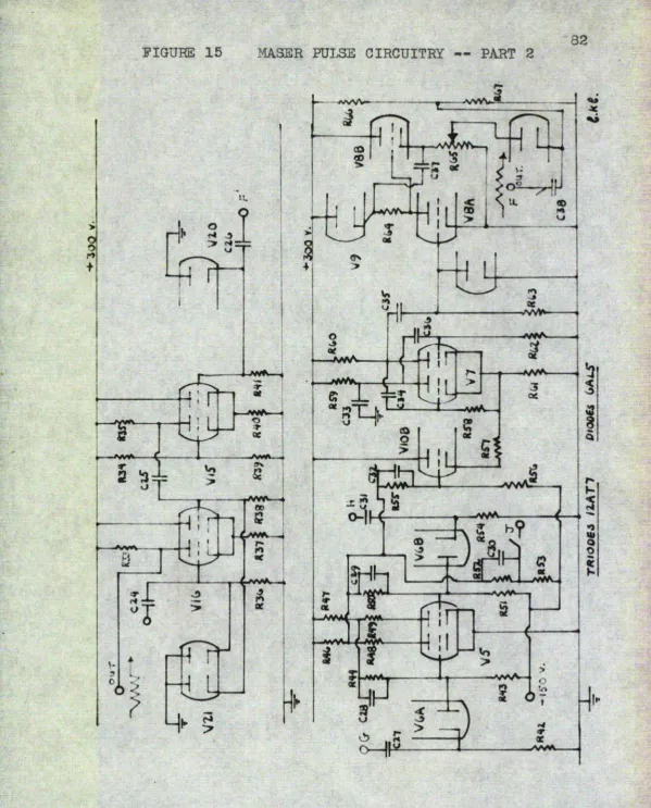
Maser Pulse Circultxy -- Part 2 ‘
Puloe Circuitry for Adiabatic Fast
II 8^
Passage inversion # block diagram 83
17a Timing Sequence rr Frequency
Sweep Method ♦ » drawing 84
I7b Timing Sequence — Field Sweep Method # ...'II • 85
là Field sweep Power Amplifier • schematic 89
19 Alternator Field Sweep Circuit block diagram 91
20 Saturation Charaoteristios for irradiated
' Diamonds ' , # graph 100
21 Diamond and Blue Blastloene Resonance . photo 103
■' * ' . \ c.* (. • *« V ■#■ *» j,.i , » kb. ^1 . » », ^ ii , ' . ' ' t page
g 5. Hgû Relaxation with ïïhdèrcoupllhg # photo.■ 3-^#
86 MgO Relaxation 'with Ovorcoupling * îV
lis
87 MgO Relaxation — bveir* to ..trhderc.oupling- Ë 11223 MgO Relaxation with Field' Sweep It lîg' 89 Field sweep Dÿiving Voltage... # II 183i.. > 30 MgO Aheorption and Oavity Reflection * If 183 31 MgO Eeeonarioe Absorption * # It lâs'
38 MgO Emission ^ # , It 183
33 MgO 000illation >ipulae with
Amplitude Modulation . • " > • V-*• ?■ >'• ' '1' ^-1 ft-, & •»! , % W 4 »^-j. -» ( , . It 186
34 l€gO Osoillatioa Eulse without '
Amplitude Modulation » .. ... . It 13P 36 lîgO 030Illation Dulse -r IP Amplifier '
' '- 3ftturp,te| . II 130
56 MgO Oeoillâtion Dulse — • Amplifier
' " UnBÛtufËtèu Dufin'g ' înfoxaïon , it 130,
37 Diamond 89 Saturation ChafaotSristic ’ - % k
CHA.ra!R 1
INTRODUCTION
1.1 The Masereroeyb»rAMy>«-w)i*«iy»
Prior to tho development of the maeer# Euaplificatlon - and oacillation in microwave devices were obtained by the con version of d-o power to r-f power through the interaction of
charged particles with an electromagnetio field# In the maser devices with whioh we are concerned» energy conversion is
achieved through the interaction of an electromagnetic field
with a molecular system which may be uncharged#
In the past# prime interest in the field of Microv^ave Spectroscopy has been confined to the study of the mechanisms
governing the absorption of microwave energy by a quantum
system. It was realisiod# nevertheless» that under certain ■ conditions • a quantum system could- emit microwave* energy upon
the application of a, prescribed stimulant# The nmm maser is thus, derived as an acronym for **MiorowaVG Amplification by
Stimulated Emission of Radiation" #
Molecular systems whioh are initially in thermal equi librium with their surroundings will absorb radiation, for in such equilibrium the energy states of the systems will be
populated according to a Boltismann distribution. If just two
energy states of an electron spin-aystern in a d-o magnetic
field are considered, the lower energy state will be more.,
system emissivo# it le neoeseary to upset this 'balance and arrange for the higher energy level to contain the larger pro^ portion of the electron population# The ease by whioh this "inversion" can he obtained will depend upon the mechanisms governing the restoration of therml equilibrium and upon the
sharpness of the energy levels#
Efficient maser operation is highly dependent upon the material whioh is being excited, and many materials are being
investigated for such use# Efficient operation in this context is taken to mean a largo gain-bandwidth product if the system acts as an amplifier, and spectral purity if the system acta
as an oscillator. In addition, the mechanisms governing the restoration of thermal equilibrium in an activated material are tempera tu x^e dependent, and thus present day masers operate at temperatures in the liquid nitrogen to liquid helium range#
The principal attraction of a maser system, however, lies in the low noise figure, or noise temperature, that can be attained* Conventional raicrowave receivers have overall noise temperatures of the order of 1800%, whereas, one obser ver^ has reported a noise temperature of 2 0 % for a particular maser amplifier* Since the principal noise contribution in a
o
system would be particularly suitable for radio astronomy
and for long range radars, provided that the galn-bandwldth criteria wore satisfied in the particular application#
There are in existence two types of maser systems#
namely: a) those which utilise emissive material in the gas eous state# and b) those which ox)erate with emissive roaterial in the solid state# It is with a subdivision of the latter type that this thesis will be concomed# For the purpose of completeness# however# a brief review of the evolution of the various maser types follows#
The first literature on stimulated emission was ascribed to Einstein^ who formulated a treatment relating the
proba-bilitias for emission and absorption of radiation in a molecu lar system when that system was under the influence of an ap
plied radiation field. The first paper exploring the possi bilities of maser action was by V/eber^ (Univ. of Maryland#*
1965)# A gaseous (ÊH5) maser was later developed by Gordon# Zeiger and Townes'^ (Oolumbia University# 1954) • This was ■ followed by the experiiuenta of Oombrisson and Townes^ in 1955
on a pulsed two-level solid-state maser* In 1956# Bloexa-
1.2 Scope of Thesis
This thesis is concerned with the development of a * two-level, X-hand (3 cm.), solid-state maser for operation at liquid helium tempo ratures. The work was Initiated as
part of a programme of investigations in the field of elec tron spin resonance at the University of St. Andrews.
When the thesis programme commenced in 1957, it was planned to develop a two-level, solid-state maser as a micro'
wave amplifier, hut it ‘became evident, with the advance of
maser technology, that the throe-level maser constituted a much more efficient araplifier system* Therefore, the thesis
programme was directed toward invoetigating the possibility of using the two-level, solid-state maser as a pulsed micro wave Oscillator.
Unlike the three-level maser, the two-level system
could theoretically be used to generate pulsed oscillations
at a frequency higher than the frequency of inversion, and it was conceivable that useful amounts of power could be generated in the millimetrie and oub-mi 11 imotrio regions of
the spectrum by such means# Since any development along
this line would be a long term programme, this thesis was restricted to an investigation of the problems associated with inversion and spontaneous (but controlled) oscillation at the same JC-band frequency.
neutron-5
irradiated magnesium oxide. To the beet of our knowledge,* ouch diamonds had not been previously investigated as pot en- • tial maser crysta.ls* Heutron-irradiated MgO had been examined by Chester et al#^*^ who obtained successful maser araplifi-cation with this type of material# However# these investi gators had not observed spontaneous oscillations with such
crystals#
6
CHâOTR a
STIKTOLâïJED Aim SDOHTMSOUS EMISSION OS RADIATION
8.1 Sinatein Transition proDaDilitios
A radiation field can interact with an atomic system to
effect transitions between stationary states of the atomic system if the radiation field contains oompononts near a Bohr frequency. Spontaxieouo transitions can also take place within the system in the absence of an applied radiation field# The
prohahilitles for such transitions ware first postulated by Einstein^ in 1917 in his quantum theory of black-body radia-
tion#
Photons obey Bose-Einatein statistics and can be treated formally as linear oscillators. In this way# Planck obtained
an expression for the energy density due to oscillators with frequencies between V and y / dV# to give his radiation law#
where C(v) represents the equilibrium energy density in the
radiation field.
In the Einstein treatment, if k and 1 represent
states of the atomic system# and and H-i ^Gnote the number of atoms in the and ith states# respectively
7
from k to 1 por second will be
% 1 " / %Bicl PCVki) (8.8)
in the case of equilibrium between the atoms and a radiation field. The first tern on the right hand side of Equation 2*2 reprosentfs spontaneous transitions and is proportional to while the second term represents induced emissions and is proportional to and to the density of the radiation
field at the Bohr frequency# The .expressions and B].-x are time-independent quantities* In the same way, the number
of atoms making a transition from 1 to k per second will
ho
% k - P U k) (8.3)
corresponding to absorption* The spontaneous transition coefficient in this case is %;ero. . The coefficients#
%^1 Bxk» ™ the above equations are called the Einstein Transition probabilities# In the state of equilibrium when the number of transitions upwards and downwards must be equal, the above equations will be equal* Then it can be proved that#
®kl = Bii5
^ 3
ami in equilibrium and are related by the Boltzmann factor
ï-»Swfj*w» * 5 gxp|^-(£k‘~ ^ (2.5)
From the above rolationshipo we may derive the Planck radia
tion formula#
The Einstein relationships have bean stressed to show that spontaneous (phase incoherent) emission at microwave
frecihencies is negligible in comparison to the coherent in
duced emission, for if we substitute values in Equation 2,4 for A^^x# at 10 kMc/s, then A^^x % % i % G % 10"^^ and hence ma,y be neglected in any practical calculations other
than on noise»
2.3 The Emissive Condition '
It can be seen from Equations 3.3 and 2.3, that if we
legitimately neglect the spontaneous transition probability, %cl^ the condition for emission of radiation reduces to the
simple form % Bx « Thus the emissive oondition requires
that the equilibrium ;po|?ulation distribution in the atomic
states should be inverted. It is further evident that after inversion# the ratio# Bj^/Hx# should be as high as possible •
9
temperature ohange from / ^initial to - ^initial# hence the initial {equilihriuia) temperature should he as low as possible* Even at low temperatures population differences at 10 Mio/s are not large* For exm'aple# with this two-level system, the population ratios would be
2 99*8^ for T z 500%
Hx
% • 3Qfo for T » 4 %
Hi
Under "steady-state" conditions with the two-level spin system a negative temperature cannot bo realized as the density of
the incident radiation field is increased* The best that one can hope to achieve under ouch conditions is an equality of populations corresponding to a spin temperature of /cO * It is necessaiy to employ transient techniques to effect a population inversion between two energy levels of a spin system* This will be discussed in Ghaptor 5:.,*
8.3 Treatment of Z m m M M U E E a M M M M & m The topic :! of transition probabilities will be discus sod briefly from the quantum-mechanical viewpoint, as the results
10
the diecuBsion will be a semi-classical one-with the radia tion field unquantized, and only coherent radiation will be considered*
In most many-body problems, the exact Eamiltonian-Function cannot be calculated# and consequently the
Bchrddinger equation can be solved exactly in only a few
simple cases* To overcome this drawback# approximation tech niques such as the Perturbation Method may be applied,# An
energy perturbation in an atomic system may be of a time-independent or time-dependent nature# The perturbing influ ence of an electric field in a paramagnetic salt such as
Ti^^#set up by surrounding charges# may be taken as an ax- ' ample of the former perturbation# The influence of eleotro-riiagnétio radiation on a paramagnetic system {again such as
may be regarded as an example of the latter type of perturbation* It is with the tinio-dependent -perturbations that we shall concern ourselves#
The time-dependent Schr^dixiger equation is of the form
^
(
2.
6)
where
H « Hq / H ’ % Hamiltonian operator for the
perturbed system
Ilg « Hamiltonian operator for the unperturbed system H* » Time dependent energy perturbation operator#
linear oombination of pure energy state functions (or, using
the Dirac terminology,, since any ket can be expressed linear
ly in terms of the basic kcts of a representation) $ the wave
function for the perturbed system may be written,
f = 2j % ( 8 . 7 )
n ' '
Where the are independent of time and related to ^ by#
f = Z ^ n ( t ) % e % g ( - m n & ) (8*8)
n ^
In Equation B»8 is the energy of the stationary state % ,
i » .pi and M m. h/BiL
Straightforward analysis for the tima-dependenee of the then give#
& E°k(t) (E,y «xp(8mx.^t) (2.9)
K
where Hnk ie the matrix element forming the representatrive of the Hamiltonian operator for states n and k, such that,
(«A) * (8.10)
V
the integration extending over the Whole volumc,V, of the
co-ordinate system, The term T^nK represents the transition
frequenoy between states n and k . ândris given by VnK *
- E^)/h# The term, Y oonjugate complex of . ^ #
If the system is - in state- k at time t ».o#- before the
12
that the system is in state n after time t* In this case# therefore# 0^ # 1# and all the other C ^ e » O a t t « 0 # s o that
Cyj(t) » i 1%
À
expCsKiV t)dlt. DK (2.11) o
#j 2 'K ( H *) exp' -2 K i ) :t/hj - 1 { p i ^
^ SK(Ej^
In the case of a magnetic dipolo transition between states
n and k under the influence of a perturbing electromagnetic field (BcosB'ÏVt) # the nk^^ element of the perturbation
matrix is given by
Ik) = II' %
r * ' ' '
B 008(8irvt)j^^yu %,av (2.13)
y
where the integral represents the strength of the magnetic dipole transition coupling the two states; where is the magnetic dipole moment#
Thus far# only two exactly defined states have been envisioned# As the energy levels are not entirely sharp# a function# # Biust be included to account for the density of the final states# This density function may be expressed in the normalized fashion
^ 4-c^^
13
When thin expression Is included in the aquarod prohahllity' * equation (Eo* 2«12) for monoohromatlo state8#.- and the result^ ant exp re 8 si on integrated over the frequency range -oO to
/ (pOy the following expression In valid for the overall trans*
ition. prohability
nk Gn(t)| (V)t (2.14)
14
OmPTBR 5
lïIüESCHaVÜ&OIG VIEI) ]P]30(BüS5i33S(5 :[]& ]EVl]3Ülî<üL(a]üIG!P:[(3 S)(%I,][D8
Introduction
This chapter covers briefly those parts of paramagnetic reaonanoe and relaxation phenomena relevant to the problems encountered in this thesis* The transitional probabilities discussed in the previous chapter are applied to the problem of calculating the power flow between a paramagnetic system and an electrormgnetic radiation field when relmcation pro cesses are considered* The relationships between power flow and relaxation may also be'expressed in macroscopic terms# aa in the Bloch equations^^*
3*1 Spin Emailtonian
As stated in Chapter 2#in order to evaluate the prop erties of a quantum system# it is necessary to establish a Hamiltonian function# H# representing the total energy (poten
tial and kinetic) of the system before an attempt is made to solve the Schrbdinger equation. l'or the case of a para magnetic crystal in a d-o magnetic - field# B» the
Hamilton-iain can be expressed (in terms of decreasing energy) by the following:
H = Vic / W / (h / 2S) .B
15
]»ea)3?Gei8a1;8 IQie (}0u]L(%m3) jLnlba]rE&(;4;jL()n ()jT iblie (3]L8()4>:fo%ii3 1)118 iiiio]Leii:a emcl if:Ll)li (sacsli ()"blie:r,k tClie lieiTDis; Vfgrg, . eiaid . v*ss represent the apin-crhit interactions and the spin-spin
jLn1)G3C2i(*1)3L0ii, 3?e83)()(!ib:lTr8l3r# 9%ie lie]?# ]rG%)]reevents; idie effect of the crystal field where V(x#y#z) is the crystal line potential# In the iron group of hydrated salts# this interaction is large compared with the spln-orbit interac tions and small compared with the coulomb interaction# In the rare earth salts# ‘ the ■effect of-, the crystalline field is (3mei]L]Le]f Ibïiem esp3Ln'*():rl3iL1) îLn1)e3?2&(;1)jLc)n8, Inil) agipsEitsip tlietn l&lie %iU()]LGsi;p :Ln1)e3f%i<>i&i()ni),» ][ai1)€>]r&kCl)3Lon tfjLlili Eiii 4B3Cl)e:c%is&]L inagS""
j[iL(%]Ld, #, (sfiresa ordLfse 1)o iblie ibeimca (l, /f ,]3 v/kieare ^^3 iLs 1)lie IkükiaT %aEkgs%i#1:o#if aincl eiricl St ]r8dre]p 1)o iblie (>]rt)jLtagL; a&nd spin momenta of the contributing electrons# Term rep resents the interaction between the magnetic moment of tie iiii()]Leus Gincl l)lie BiBLgçiieibjlc) iT3Le]Ld *3<&t iijp Togr Iblie ();pt)i1)al aiiidl
g&]pin ai()men1)E; ()jF Iblie <3le<3l)]ronE&# JT zredTejcs 1)() Ibïie 1)()i}2&l Ein(gii"» lar momentum of the electrons and I to the nuclear angular Biomenl&umbr j^jlneijL Ibeicm,» «" :rejre:m5 1)(> 1)lie (l;L:re(;1)
interaction between the nuclear moments and the external Bia(&ne1):L<) dTdLejLd,?;#,, i*%ie:pe $: %iu(3]L65i3P azsLlidLc»,
16
Type of interaction H^hitude Optical transition few e-v Molecular vibrational transition 10^^
Molecular rotational transition lQ-4 io*~5 Orientational energies of para
magnetic ions in usual labora^ ** " » tory fields (3000g)
Orientation of nuclear moments 10**
3# B Paramaenetio Resonance
Paramagnetic resonance occurs when transitions between the Zeeman levels of a spin & system are effected under the stimulus of an electromagnetic radiation field# The energy levels are appropriately separated by the application of a d-c magnetic field* Maximum interchange of energy occurs when the magnetic field vectors are orthogonal*
The condition for resonance is#
h f - A E « ' gAB (5.3)
where f » transitional frequency; g # spectroscopic split ting factor * 2*0023 for a "free" electron; Bohr mag-neton = eX/Bmo « 0.92? x 10""^^ erg/gauss; h * Ztji - 6.62 x
erg-sec ; is the separation of the neighbouring %eeman levels* One may also relate g in terms of a gyro-magnetic ratio y where Y = g{/^/)()*
As will be shown# power absorption is proportional to o
17
a frequency as possible* The upper limit for operation is mainly limited# however# by the availability of components in the high frequency region# Because of such limitations# X-band equipment was selected for this thesis#. X-band com
ponents were also reasonably plentiful as i war surplus* At X-band, f 10 Mic/s and the d-c jmgnetic field is
required to be in the order of 350Q gauss*
3*3 Spin-Lattice and Bpin-Bpin Eelaaaition Processes
If the energy levels of a quantum system were perfect ly sharp# as was assumed in the first part of the transi-tion-probability analysis in Ghapter 2# energy would only be emitted or absorbed by the system at a jaonochromatic fre quency under the influence of an applied perturbation* In actualitj^# the width of a spectral lino can never bo less than that dictated by the Uncertainty Principle#
AW.At ^ h/21\ (3*4)
where the "width" of a spectral lino is defined as that fre-quency interval in which half of the emitted of absorbed energy is contained# In Equation 3*4# AW is the energy
spread of an excited state and /[t is the average time spent by the atom or spin in that excited state#
18
spread in energy would correspond to a "natural" line width* f where
(Af) - & 1 (3.6)
2'K
and whore is the spontaneous transition probability coefficient given in Equation 2*2* In the Biio.rowave region* however* the natural broadening will be negligible in the
presence of other broadening processes* As described below* the principal broadening processes encountered in paramagnet ic resonance work on solids are due to spin-lattice and
spin-spin relaxation effects*
In the presence of a perturbing radiation field* a spin system in a crystal lattice will (in general) absorb energy* Since the spins are coupled to the crystal lattice through spin^orbit and orbit#lattice coupling# the lifetime of an excited state will be shortened by this process* Such a relaxation process is temed a spin-lattice relaxation
process* In accordance with the Uncertainty Principle* such a relaxation process would increase the energy spread of
an excited state and thus the paramagnetic résonance line would be broadened*! If or the type of maser considered here* however* an operational requirement is that spin-lattice
19
this effect* The spin-lattice relaxation prooeeeos may be described in terms of a time constant# T^# and this time constant is defined here as the time taken for the spin sys tem to couple (l l/e) of its excitation energy to the crystal lattice in the absence of an applied perturbation.
The spin-spin interaction arises from the fact that the total d-o magnetic field acting on an electron in a paramagnetic molecule is that of the "external" magnetic
field plus a contribution which is due to the magnetic field set up at the electron by the neighbouring electrons# 6uch a contribution will result in a spread of transition fre quencies over the spin system. If the spins are made to process in phase about the external magnetic field axis, at
the instant t = 0# a coherent magnetic moment- will be set up at that Instant in the (x-y) plane orthogonal to that
field (îs) axle. The spins will subsequently suffer daphas-ing# and the coherent magnetic moment will decay to ziero as the spin system increases to a state of maximum entropy. The time for do phasing may be described as the spin-spin
rel&txation time. The spin-spin interaction may be reduced by magnetic dilution of the paramagnetic salt* whereas the
20
3*4 Saturation
Saturation* as will be described here* occurs In the absorption of radiation by a paramagnetic molecule when the absorption is not linearly dependent upon the density of the applied radiation field* In the i)aramagnetio system* as the density of the applied radiation field is increased (slowly)* the number of spin transitions to the excited state will in crease* Eventually* as the radiation field density is in creased* the relaxation processes are unable to effect a speedy return of the excited spins to the ground state, and the population difference between the spin states will de crease* When this happens* there is no longer a linear dependence between the absorption processes and the applied perturbation* and the spin system is said to approach satur ation* Gomplete saturation occurs v/hen the two population levels of the spin system are equal* and in this case-the paramagnetic system may be said to be transparent to thé
incident radiation#
As has been previously stated* an excess of spins in the excited state cannot be obtained by the application of a "steady state" perturbation. If the state population has been inverted by some means * however* it can be postulated that in the inverted state* a departure from linearity be tween emitted power and the applied perturbation will occurW#. in**#».# ^ ^
21
As shown in Section 4*2# the magnetic properties of a paramagnetic crystal may be described, in terms of a complex susceptibility % = . c % # where and relate to the phenomena of absorption and dispersion respectively* The magnitudes of the susceptibility components andX^^ depend upon the degree of saturation of the spin system* Such components will be pzero for the special case of a completely saturated (equal populations) spin ^ system* 3*5 Power Plow between the Paramagnetic Solid
and the Radiation Pield
The instantaneous rate of energy transfer# p. .# for*jtki e. a spin transition in a paraiaagnetio molecule is# by the
application of probability theory#
O - d (spin transitions . .
'^ins* "" (hf) X p r o b a b i l i t y ) (3*6) dt
and the average power flow# between the paramagnetic ' system and the radiation field (assuming absorption- for aim-plicity) will bo found by integrating-the above expression
over a distribution of times# such that#
^av. ” ^ins.* Pr(t)dt (3.7)
22
transitions as tho result of a- perturbation by-a raiorowavG' ' olectrio field# The 'expression is derived' by the method in-dioated in Equation 3*7# but includes* the result, of a» mo re specific probability treatment'"than that givoir in Equation* 2*12# When the effect of spin-lattice and qpln-epin inter action s is COnsid.e red# we have :
. . ’ f ■ • ■ - . • ■ . . 1 - ' ;
B.Field" STgh ’ (f-f )^ / / h('jsi)®
Where
p % electric dipole moment ^ - *...- - ' É z amplitude of microwave electric field
f« s resonant' frequency'for transitions Ti a spln-^lattioG . relaxation time
T^ » spin-spin relaxation time
For a ’Single electron in a microwave magnetic field. Equa tion 3.8 would hold if p were replaced by the magnetic dipole moment# # and 1 were replaced by the amplitude of the microwave magnetic field# B^#
: ■
2T^h (f-f^) /
neglecting the last term in the denominator of Equation 3#8
83
D, "molecular" bandwidth# {At), to the system# namely#
- >. '
(Af) it -i_ (3.10)
«1-3
How the pov/er absorbed by the spin system at resonance will be twice that observed at the frequency half power points.
If therefore# in Equation 3*.9 # wo select the (f - fq) term to equal (Af)/8# the power interchange will bo
B*p2
a 2 •
. 1
V "V «P«IW.BflÉrnrÉl - W f till -veiiWSRWW
2Tpii (Af) 2
. -JL. (3.11)
h (Af)
The above is the result derived from consideration of the transitions of a single electron. For a spin *è‘ system con taining H spins# Equation 3.11 would be multiplied by the population difference# dîf# between neighbouring Zeeman levels. Since to a good approximation#
h f H • (3,12)
the expression for the power absorption in a spin k para-magnetic crystal containing II spins becomes
fP \ a «
which is in agreement with the expression quoted by Oomhris-» eon and Townes^* Hote that this equation has been derived in the Gaussian system of units* * > - *... • •
In all the above expressions# has'been'taken* to/rep-resent the amplitude of a pulsating microwave laagnetic .field* Circularly polarl&ed microwave-magnetic* fields are required' for transitions, however, * but o,ny pulsating field may "be ox-pressed in terms of two - half-amplitude c ircularly polariised components rotating in- - opposite directions,
3.6 Tie - Bloch Formulation ' ■ ' ... ... ■ ^ ‘ ' The Bloch equations^'^,^ originally ' applied' to thO' nuclear'-magnetic resonance > phenomena):^, may be applied to > electron* ^opin
resonance phenomena, if^ one* is interested in a classical* under*-standing of the transient and steady state * response - of > an elec tron spin system under the stimulus-of an applied radiation ' field* These equations, now written to relate relaxation pro cesses and magnetisation changes in an electron spin system are
dt s coa w t - MjjBo) - IxTa
_ V / j. „ I-. , \ t ”*
(3.14)
25
Where is the. denslty^ of the <i-o magnetic field which is applied along an arbitrary Z*-axis| -is * the* steady* state raagnetization- along the Z-sixis in the absence of -a ‘ » perturbing radiation field; reprepenta the time dependent* component of the magnetisation along the Z-axis* as the result of such a perturbation (B'» 2Bi * oin w t ) « - a n d - 14^' » are* ‘ the projections in the * x-y- plana* of the*precassing iaagneti-nation vector M;; Y # the gyromagnetic ratio for electron spins and and are the relaxation terms previously described. - ... - * -... , . . >. ■ *
The real and-imaginary- oomponent of the magnetic sus-* ceptibillty of a paramagnetic solid may be derived from the solutions to the above equations^^# namely
' ■ ' • (Wo'-cJ)'Tx '■
X X
— ■ : 1
where the expressions are in Gaussian units. The Y B^T^To» V* f * * J * V îj»' term in the denominators may be called the saturation term. The effect of this term on the susceptibility components is illustrated in Fig. 1, whore- the normaliz&ed susceptibilities are plotted against the dimenslonlesB product ( A)^ - d) )T2
26
oa
1*0
A iXô^Tl m '"'1:
p-i
■. -y', - c - ; ' ' f ' 'yv;
3?
An-exaanination of the -oharaotQ rlatlo8 of reCloot ion-cavity paramagnetic resonance spectrometer# ope rating-unde r steady state conditions-wiX-1 show that the- oignah reflected from the cavity will, in general,-he a,function of % ^ and
* In practice with ordinary diode detectors there will> he no response to phase-modulation, and the detector -output' will he proportional- only to if phaae ' sensitive .elCM, ments are Included* in- the cavity- arm of - such - a ci rouit ( e*g#,
for coupling adjustments),■distortion might occur in the wings of the absorption charaoteristie if the* dispersive ^
effects -are large enough to affect the- coupling' of - the- cavity* It will he seen that if- the saturation- term' is -included in the power expression (Equation 4* 11,-or in Equation-3#9
when applied to the case of a*-spin- density of H* spins/o. c), - ' and if the density of the perturhing microwave field approach es oO , the power ahsorhed hy the spin system will, in this limit, approach the maximum value,
p(oO) : Hdjo 1
9.
»
IsS
/ unit vol* (5*16)-1
From Equation 3# 16-- it will - bo seen-that th#\-tempoa*a1>ur^-'0f t w spin system will approach oD - as the spin lattice re*? laxation time appyoaohee infinity# . . .. .,
Experimentally, the magnitude of the .saturation-term^
may he calculated hy noting the deviation of - the- aheo rpt ion
ohayaoteristio from linearity as a funotion-of the-incident' ' microwave power# The ratio of the anticipated* to » the* emperi-mentally ohcerved aheorptiono will give the eaturation%term directly# These ohservations will hold for the oaee of - ' homogeneoualy broadened lines#' The* molecular reeponee,how*»
ever, will he a more -complicated function of frequency - f hr
inhomogeiwoualy broadened lines#' Ae-indioated hy
S9
a m m 4
OIROUIT miATI0N8EIP8 FOR A PABMIAGEBTIO 801ID IE A mOROWAVE EEFIEOTIOE OAVITY BilGOEATOR
Introduction... - ■ ■ -... As shown in the • p rev i ou a chap t or,- the« ah s o rpt ion of * energy hy a parimiagnetio solid ip proportional to the -power density of the porturhing'-microwave' magnetic
faeld#'Thie-radiation density Biay he » conveniently increased if the- para magnetic spooimen Id located in a reeonant-cavity.-^-Reflect
tion^type cavity resonat ore-we re employed-in-this the-eie-in preference to tranemieeion-type reBonators,-tO’ simpl-ify the' prohlema as so dated with cavity coupling, and with heat con duction into the cryostat... - • '
-The circuit properties of -reflection^type cavity reeon-ators are briefly dieoueeed in this chapter, as they-relate to the absorption (or emission)- of energy by a paramagnetic solid. Conditions for amplification and oscillation are doTivod, and 11lustrative axamples given, and a f igure of merit for the system is derived, in terms of a gain-handwidth
product. ■
4*1 Resonant Cavity 0. Factorli«M 11 HnWl i KH» — # # ''*■*«>K» «i'-«
30
where
W « energy bdnt’ainéd "by the mlorowaye fields In the cavity • " *
p - power loss to' the cavity' walle* ' ' ' ' ' ‘ ‘ / where . is the rasonant • frequency • w o "
Furthermore we'may express the energy storage in\terme of the oscillating magnetic (or electric) field intensity. -For a TE 101 or a TE 102 resonator, thie, .expression reduces
to
"O
where
2
^ — iJk * (volume of resonator) {4*2)
8 u.
(2B^) a peak amplitude of" the microwave magnetic" ' ; field'density (wehors/p* s.m.) over the- cavity
Uy js magnetic permeability of. free. apace - 10~^
and where the relation is expressed in un rationalised m.k. s.
uni t s • V.' a- ► ^ k , t.
in practice the cavity must he coupled to a signal-source. As a result it is necessary to define an overall— Q for the system, f in-terms of the s associated with the cavity and the coupling losses, as follows,
3 (4.3)
% % .
51
4*2 Effect of a Paramagnetic,. Solid in .the Oavity. . .. .
' •
'As shown in Equation 3# 13, the- power absorbed'by* a spin paramagnetic crystal in a radiation field will be
kr{A t)
When the spin system is - unsaturated# This equation may be applied to the case of a paramagnetic solid filling a reso nant cavity, if the - density of the magnetic f ield, is* redefined as in Equation-4*2#- -The effect of this solid on the power losses within the-cavity system may be-expressed ‘ ' in terms of a magnetic Q, factor, In.this event, the over all Q, may bo written in the form,
( 4*4)
% Qo %iX
where the magnetic - Q factor, is positive in the case of an absorption,■and negative in the case of an emission of
power by the paramagnetic solid* - * . . . The magnetic* % factor may also* be-expressed in terms of the imaginary part of a complex magnetic susceptibility
X
§who re :
J - J ’ - iX« (4*5)
33
1 k s. ,v, s I
eleotroraagnetio* radiation f ield of a m p l i t u d e ' . by an unit volume of the magnetic opeoimen per cycle. will ho
^cyo
s <b B dîi
(4*ô)
I - « ^ ^ ^ ' »» K ' k * * : b '« t v b n î i % ^
Where M a magnetisation per unit volume m /C b/uq
B * Sin Cl) t Uq a -o - 10'
Thus
dB a Bx cos
cot #
d(C0 t)and ; k. ■ >■
^cyc * <f ( y* *. 1 J'pB^slnat oos»t d(wt) (4.7)
On Integration the term in ^ • drops out and the expression for pgyg reduces to
^oyc ■ Ü —hi / unit vol. (4.8)
For the general case Of a paramagnetic-solid in an uniform electromagnotic field; the energy storage in the field per unit ;■ volumo will he^^
> g
¥ » (4.9)
so that
33
^ - .-ii/unit volume (4#ll)
, ^
which agrees with the expression derived by Gordon, Geiger, 4
Q ^ n d T o * w n e s * .. * « ■. . « » ,*,i i . . . » * > . * k *
■An expression for the magnetic % factor of the para-magnetic solid may be derived from Equations 4*4 and 4#11, namely, . '
'im * - p ^ T (4.13)
where the ooApleX' susceptibility component;rX becomes nega^ d
tive Wkien the parcimagnetio solid ie emissive # 4*3 G ondi tiens f o r Re/icone rat ive * andmmmttmttrn m m nnm ■ iili w — iimimw J,vnii.»i
Suver^rep:emmii¥ô- Maae-r -,'Act ion * ... . ...
A necessary oondition for regenerative amplification' in the maser system is that the- power • supplied by » the para magnetic specimen in the resonant cavity shall exceed the wall losses in the resonant oa,vity; that is,
l : > i- (4*13)
%o
^ In the general case, the coupling of the.electromagnetic energy to -the spin system should be taken** into considération,-in which case, the expression % considération,-in Bquation 4*12., would , be multiplied by a''filling factor”, , add v\ may be defined
aat Bp''.dVp/(r' 4 ^iiere.the upper.
. 34
It can be postulated that ^ Equations %3*&3 and ,4'.dl' will hold for omission as well as for abeoyption if tho^^ epin^ temperatures'(negative or poeitive)' are low-in both Inetanoee# Xf this 3.0 ■aooepoed, Equations 5-* 15 « ■* -and"4#-11'- -- may* bot equated for emissive behaviour* . If the relationship is'expressed in Gauoeian units on a per unit volume basis, we have#
(4.14
kT ( Af) / 1 8
where IT ^ -is now the number of participa ting* epine per, c*c*, and-where ie the volume of the paramagnetio solid, Whence - ; " '
4 1 fX"1« H A ( 1 » 3 ) (4.15) M Ï .
Where IT is the total number-of participating aplna* ^ , : Ae ah illustration, let » 2 x 10.^;: f a *9*1 X )L0^ ops # 6 CCI- T. » 4%; ^ #' * • Then' (-.sirAoe^^-s»'0*93 x
erg/gaubs$ k # 1*3? x erg/#egree) the oonditloh for - ' amplification expreeeed inEquàtion.4:*13. reduces, to.the condl#' tlon tiiat CH%) > vw.4*8'3e1G'^. Fo-i< a libe wiaijK. of'1'gaugs , To in thie illustration is approximately ^ XQ,
sec* (since df s 3#8dB % 10^ cpe*), and the condition for ’
35
amplification in the illustration reduces to
ÎÎ > 1#2 X 10^^ spins
The. condition for oscillation# on the < other hand# is -that^ the total % of the system should he negative* This necessi tates that '
M i.
Qm
>
i- / i- Qio Qo (4.16)If the resonant cavity is nearly matched to the source wave guide# we have
1:: / 1: % 3_
% %0 %o
If this approximation is assumed to he valid for the above illustration, the condition for oscillation becomes#
^ y 2,4 X 10^^ spins
4*4 Gain-Bandwidth Product ... ... ... The 'gain-bandwidth-expression for a reflection cavity# regenerative m s e r with circulator, has been derived by Burk-hardt et al#^^ The power gain, G# of the system with a
circulator in the reflection arm is-p P where f- is the cavity reflection coefficient* _ It can be shown that#
36
Where a is the m#-bancl^ .poMcy gain,# ..l/% » 1/%^ / i/q^ / l/(^* Equation 4*17 may be reduced to#
' '•- ' " > K. i
(G^ - l) S-, %
-â.
(4.18)6)0 ^
Where B - is the bandwidth between half-amplitude points on the response curve# - ' • * ■“ * ...» »
As shown in Fig# 3#-page 51 #- a 10 db directional' coupler was employed in the* reflect Ion'path of thO'maser in this-'in vestigation (for reasons' of economy) and in this case# the
system gain to this point would be#
( # # 1) ^ iA. . i,
37
OHAPTER 5
I1TVER8I0B ORITERIA AND OHOXCE OF FARAliAGNETIG CRYSTALS
Introduction -... ... .. • . ... -. Tho discussion has ao« far ■‘been liiaited to the' behaviour of the afin system following inversion# In this ohafter, In version techniques' will be diacuaaed as they apply to-the
problems of this investigation# - The^ rest of the chapter will be devoted to a detailed statement on the paramagnetio media
employed# ■
-6#1 Inveraion-Teohnigues ' - - .... , » At this tiiae-there-are-three-Aaethoda for exciting a paramagnetic crystal in a two-level spin system* These are;
l) Pulse inversion ■ » - .. ... S) Adiabatic fast passage frequency sweep method
3) Adiabatic fast passage field sweep method* - '
l) In pulse inversion# a short# intense pulse of zaicro-wave radiation is applied to the spin system at-the resonance
frequency while the-d-o imgnetlc field is held constant at the resonance value# With this method# since the » rates of fre quency sweep'are - large # it is » necessary to-evaluate the quantum mechanical' transitional probabilities before-the ■ height and. duration'of the* inverting, pulse can bo determined#
31
38
a pulse of mlorowaye power at the resonanoe frequency for a time# t# such, that
5j 1 ( 5*1)
h ^
(where is the magnetic dipole moment and ^ the ampli^^
-tude of the miorowayO' field) # then the state populvàtions*' will he inverted. It can-he seen# however#- that- hoth- tho^ Biagnetio field and the per turhing frequency-have to-he held at'the *
résonance value# whilst in addition# the pulse time has to he critioally seté - Thus# this method would not he too easy to
apply m praotrce# ... ,i >», »
2) In the: frequency * sweep » method # the d-o magnetic field is held at the resonance value-and the power klystron frequency swept through cavity resonance under the following
QonditionsS' - - • » -•... ». .., >, '
a) The - passage must - he adiahat ic- ~ that is# the
magnetÎËsation# M# past follow the changes in the effective mgnetic fields - For convenience# the-mot ion - of H-can—
he referred to - a co-**ordindte framovrotating'i at^. angular" 5
i:-frequency # ahout the d-"C magnetic field vector# Bg# when the paramagnetic sample is euhject to a microiArave
as the miorowave field. The effective inagnetio field will ■be. , : _ ' . ‘ •
% f f s Bi / ( % » S T f ^ ) (5.3)
Where ^ is the electron gyromagnatic ratio# &t raso-* ‘
nance# the e%praesion reduoea to -fPhe magncti**
sation# Mi' will pracaae about with angular frcquen"
oy jQw where : . ^
J I 8 ^ (5*3)
IVhan viewed in- the statlo^r/' system, M will" nutate about the at the same f r e q u e n c y T h e effective'mag**^ netio"'‘field reverses^ as the perturbing radiation^ paesee .
through resonance^ and the orientation of M with respect to Bq will he re versed# • ....
The adiabatic condition is thus^^i
( X %)"^ /< t (5,^
where t is the timie taken to paee through the resonance half width of the spin eyatem (aeeuming that this reso?^
nani^e is much, sharper^ than.the.jcavity. resonance), and where
(BBx)‘ le the amplitude of the pulsating microwave field
-40
8 % X 8*8 Mo/gauaa» the adiahatip condition would reduce
w .« t- t* .»>“
to A
t » 4,5 X 10" $@08,
R * i. K» ‘ W »* ■» % » % # . k & ,M, t I *. -j i % •* « « # » ’•<•
b) The condition -means that the^ reaonanoe pas- ^ ^ '• !
sage in time# t# should be very much less than.the* 8^1n*lat~ tioe .relaxatlcn time# T^# Thus, if t * l0G(4#b x seo * 4#;b mioroaec# and ^Y is-in the* same ratio# it can
be-seen that in this •-particular •instance#* T^ "Would- have tc be greater than about- 450 mlorosece-for efficient* inverclon#
■■ o) A third condition" la that the inverting? power ‘ level should -be - sufficient to produce an appreciable'eat# uration of the epin eystem^ under steadyv state- conditions#^
Mote that with this - technique» - the molecular. re,sonanoe-should _ be. much sharper than the- cavity- resonance. * - If « this- is not BO# then only a portion of the spins, in the paramagnetic -ea^iple will be Inverted# Furthermore# after inversion# unless special precautions^^ are -taken# there will be a high proba^-bllity that the stored spin energy will be rc^radiated spon-*
taneously immediately after inversion# Both drawbacks can be avoided by the use of method 3*
3) In the field sweep method# the- frequency Is held constant at the cavity resonance value while the magnetic
41
« . , . . t t » , #,4. .t i * ï
• With the field-sweep method, however, the tendency for spontaneous re** radiation is avoided as the * magnetic field is taken off the resonance value immediately after inversion-is effected* Furthermore y • «all the- spins* in the resonance dis** tribut ion will be-affected provided that* the- field sweep-amplitude is greater than-the *^»full^‘ width of the spectral' line concerned, Mote that with* methods 2) and 3*), the pas* sage through resonance can be in either direction*
5*2 Paramagnetic Crystals Inve-stip:ated - - •-•••
' In the previous cection-the restrio11ons- on- spin*lattioe relaxation time have been-discus-sed with respect to-the re* ' quiromento for this investigation. In addition- it can be- de* duoed that if the system is to act as - a * narrow* band r amplif 1er or oscillator, the width of the* resonance line associated -with the paramagnetic crystal- should be as narrow as possible. Also, the paramagnetic - resonance line width should be less
than the field sweep magnitude if-this adiabatic fast- passage method is used. Thus paramagnetic crystals with spectral
line widths in the order of 1 gauss or less would be likely to fit the field and other requirements* With the frequency
sweep method, however, the spectral line width would have to be much smaller than the resonant cavity bandwidth* A typi*
cal operational bandwidth for- such a resonant cavity is ap* proximately 1,5 Mo/s -* thus the--spectral line width in-this
A:
42 •
* .»> ... ti • I.' & <• . t*-#. 1, &« «*■ . % *. b 1 >• Vf. ^1 . 'V li ». V inversion," With the se - point s - In mind#. & statement^ wlll-nbw
be given on the paramagnetio oxystale employed in this in* vest igat i on » ••.>.•. . • - » «... » « . ...
6*2 (a) - Meutron Irradiated Magnesiim-Oxide - - - ' It has been : found that defects (F o entree)- may- ba^ in*' ' troduoed into oertain'orystals as a* result of neutron irradi* ation^^* 'In partieular#'Weeks^^'« has studied-the electran-' spin resonance speotrum of such induced-F' centres in drradi#^ « ated MgO# Me postulates that after-an* oxide-atom'is-displaced from its nomàl position by neutrons, an-electron# donated by divalent impurities present^ may* beoome trapped-at-the vacancy# Such F centres* Which haye onlyMg^^ and Mg^neighboursgive^ -a single réson-ance line with g &-amp; 2#0023#- while those : with-one or more îlg^^> neighbours give hyperfine patterns' corresponding to the nuclear spin value* of ' 6/2 (six, spectral lines) # ^
Furthermore# Ohester^*- examined crystals of neutron irradiated quarts and neutron irradiated MgO in a twpi»level maser system. He* observed maser* amplification and oscilla?^ ‘ tion with the quarts specimens at 4#2%C# and maser amplifloa^
tion (but not oscillation) with the MgO specimens at the same temperature#
43
Three HgO crystal epeolmens were Irradiated as follows*
l) Bounreay M^Q.-Speoimen* . .. . .
By the oourteey of. the Industrial Group at the Bounreay Works of*; the lînited Kingdom Atomio IBnergy' Author 1 ty#' Thurso# Scotland# • an MgO,- ory.stal wae- ''irradiated * at * that-Ketablieh* ment# in a reactor oommiOBioned-to run at a full' fluk of"'^
10-^n/cm^/sec# - From* irradiation, details quoted* by. Weeke^^, the following irradiation specifioationB were drawn up;
1) Material*^ MgO single oryâtal (elice)
-2) Weight# l»-78 gmei-diara*.#‘l-‘Cmi‘thicknese# ‘2ma*
3) Type of* irradiation **-fa'ét nedtrone (^1 Mev) 4) Dosage 6 x n#utrone/6m^' *
-6) Temp*‘during irradiation- preferably- below 100% 6) Badioactivity of specimen- within safe handling
rang© (o*3 mllliroentgen/week)
At Dounreay ' the epeoimen wae irradiated with an -estimated( dose of 10^^ * 10^^'neutrons of-energy greater than 1*5 - ► M©T (date# August 1959) * On receipt of this specimen* (which had a count rate for % • radiations, 0,B-milliroentgen per week).# it was observed to-be almost black in colour* After a month# however, it had changed' to a (permanent ?) royal blue
I 04
44
2} liarW01X beo rmens -... * « « . _ i
<8/-courtesy of the Atomlo Energy'Becearoh FetabllsWsnt, two MgO -osystsls were * irradiated^ at Maxwell# ' lu- this, qase 'the specimens weighed 0#$8 gms and 0#91 gms# reepeotlvely*; - Each speoimou'was'-a'SMce of a single crystal and wae\of-diameter 1*3 0)^0 and thioknees 9 mm# -The s-arae. irradiation,speo.ifioa*^ tiono were submitted ae foxvthe Bounreay specimen#. - - *
' At''Harwell-•eaeh o rye tab reoeived approximately 2# 4^' x ' ■ ' 10^^ fast neutrone at a temperature of(dates-August.. 1959) The radiation count was negligible# iaeh of the crystals
(originally opaque) returned with a royal blue (.permanent) colouration* From •Weekst irradiation estimate * of. #*#' fast -neutrons per ? centre# the number of centres was adjudged to be 4 X 10^^ par*crystal#' ... ...
The crystals were later* truncated to fit the smaller' dimension of the m 100 resonator described in Ohapter 6
the truncated dimensions were 0*9" mm, and the. weight of each ^ crystal was now 0&72 gms# Thus, by Weeks* criteria the number of spins in the reduced specimens would be 3*3 x 10^*^ spins
per crystal. - ► .
45
The ailcrowave spectrum of' neutron—i*rrad,ia'teds âiamondis
33
has 'been studied by Griffiths et al* , who ehow*^ that- there-^ » are two main types of absorption lines*: a) a-aingle ieotropio
line with a g- value of 2,0038 (for a free* eleotron^ epin,
3,0023) the intensity of which can* be greatly reduoed^ by 'heat»"
ing the diamond to about 1 0,Of and b) many leae - intense* *
I860' hours black ' "
VO gau88
anisotropic'lines whose intensity is not much defected by hbat treatment, and Which appear to arise from centres with elec tronic spin -S r 1* -■ * • ‘ • • ' ' “ - V i '
These investigators have obaervad the-.diamond, ooloura-tion and. line width ( ^B) as a funcooloura-tion of irradiaooloura-tion, as iollows# ' - . V. '' V , V » u s.%. ♦ ,1.,
10 hours * pale‘green 30 gauss 15 gauss
ere "cne integrated neutron' flux for an 1000 hour exposure was 9 x 10^^ n/om*^.)
The diamonds employed in our investigations were kindly supplied by the Pliysics Research'Laboratoryv University ' o f -Reading* 81% specimens were obtained with the specifioations as shown in the table on the following^ page, The crystals were irregular slices approximately 0,5 mm thick and 4 mm
in diameter.
Irradiation tIme s Colour; '
/iu at 390%;
Ab st 90%;