IEEE Ultrasonics Symposium, 2009-09-20 - 2009-09-23. ,
http://dx.doi.org/10.1109/ULTSYM.2009.5441460
This version is available at
https://strathprints.strath.ac.uk/14643/
Strathprints is designed to allow users to access the research output of the University of Strathclyde. Unless otherwise explicitly stated on the manuscript, Copyright © and Moral Rights for the papers on this site are retained by the individual authors and/or other copyright owners. Please check the manuscript for details of any other licences that may have been applied. You may not engage in further distribution of the material for any profitmaking activities or any commercial gain. You may freely distribute both the url (https://strathprints.strath.ac.uk/) and the content of this paper for research or private study, educational, or not-for-profit purposes without prior permission or charge.
Any correspondence concerning this service should be sent to the Strathprints administrator:
The Strathprints institutional repository (https://strathprints.strath.ac.uk) is a digital archive of University of Strathclyde research outputs. It has been developed to disseminate open access research outputs, expose data about those outputs, and enable the
Abstract — This paper describes the design and fabrication of a reduced element count annular array for far field NDT imaging applications, built with a random fiber piezoelectric composite microstructure. An annular array design is considered, spatially it offers axi-symmetric layout while reducing number of array elements, which could potentially result in a significant reduction in the cost and complexity of building an ultrasonic volumetric imaging system. Modelling and preliminary experimental results are presented to evaluate the feasibility of this approach.
Keywords— Far-field imaging, annular arrays, phased arrays
I. INTRODUCTION
WO-DIMENTIONAL (2D) array ultrasound transducers have received much attention in recent years. A typical 2D array configuration consists of a grid of miniature piezoelectric elements, each being addressed individually. The wave-fronts generated from each of these elements can be time-delayed and synchronized to create an ultrasonic beam for which the beam parameters, such as the steering angle, focal distance and focal spot size, can be modified electronically. This is extremely advantageous for NDT applications as it allows dynamic focusing, electronic scanning and volumetric imaging of a test piece, all with direct influence on inspection time and accuracy. Based on the array element layout, 2D phased arrays (PA) are classified into many types; this includes conventional densely packed rectangular arrays, annular arrays, and random arrays [1]. While 2D arrays offer numerous advantages, their use in NDT applications is often subject to many technological limitations. This paper describes the design and fabrication of a reduced element count annular array [2] for far field NDT imaging application. The individual elements of the proposed annular array are formed in situ using a random fiber piezoelectric composite microstructure. Field modelling results are presented for the annular array design. Performance comparison (array element directivity, beam width and sidelobe levels) with a conventional fully populated 2D array
is presented. A fiber composite array prototype device was built for preliminary investigation. The performance evaluation of the annular array prototype including operational impedance, directivity, pulse-echo and cross-talk measurements are reported.
II. ANNULAR ARRAYS FOR NDT
A. PA design consideration for NDT application
In PA imaging system the image resolution is mainly governed by the beamwidth, which is directly proportional to an array aperture. In other words, larger arrays offer improved resolution. Also, grating lobes (a form of aliasing that occur as a result of periodicity in a regular array layout) occur in the array directivity profile, when the inter-element separation is more than /2. Consequently, in order to realise large array aperture, higher number of element counts are required. More elements mean more array controller channels and a substantial increase in array instrument complexity and cost. Consequently, one of the main challenges in 2D array usage in NDT application is to design arrays with reduced element count and without compromising imaging capability.
B. Annular array description and modelling
Annular 2D array geometry is considered for the preliminary investigation in this paper. Unlike a 1D annular array which has no steering capability, the 2D configuration could potentially offers a reduced array element count design, while having axi-symmetry layout and a larger aperture compared to a fully populated rectangular configuration. However, they are limited to only far field applications.
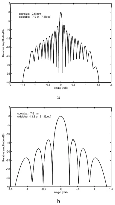
An in-house frequency domain model based on the Huygen's principle is used to predict the directivity profile Figure 1a of a 64 element annular array configuration. For comparison, the field directivity of a fully populated 64-channel 2D array is shown in Figure 1b. Note that for all modelling analysis presented in this paper is performed with no steering, unless otherwise stated. As expected, due to the larger aperture of an annular array, the beam width is reduced by approximately 30% in the example shown in Figure 1, when compared to the
An annular array with fiber
composite microstructure
for far field NDT imaging applications
S. N. Ramadas
1, J. Dziewierz
1, R. L. O'Leary
1, A. Gachagan
1,
A. Velichko2, P. D. Wilcox21
Centre for Ultrasonic Engineering, University of Strathclyde, Glasgow, UK
2
Mechanical Engineering, University of Bristol, UK
expense of an increase in the sidelobe level in the case of the annular array, approximately 5dB in the example shown in Figure 1 – this will results in a loss in imaging contrast. However, it will be possible to improve the image by applying post processing technique, such as effective aperture compensation technique [3].
a
[image:3.612.329.544.59.233.2]b
Figure 1. Array directivity prediction for (a) a 64 element 2D annular array and (b) a comparable fully populated rectangular 2D array (8 by 8 elements)
Certain NDT applications require only limited steering capability from the array. In such cases, it might be possible to increase the inter element spacing (i.e. more than /2). Figure 2 presents the parametric sweep modelling carried out to highlight the effect of element separation on the array field profile. It is clear from the results that the spot size doesn’t improve as fast as a classical array in the case of an annular layout. However, Figure 2 illustrates that for a given element count the annular array has superior resolution capability in the far-field. In addition, the effect of inter-element spacing on the average side lobe level, shown in Figure 2, is particularly bad in the case of a conventional fully populated 2D array configuration for the extreme cases. This is largely due to the fact that the effect of grating lobe is much stronger in this array configuration, when compared to the annular design. This behavior indicates that annular array more suited for sparse array configurations.
Figure 2. Effect of element spacing on an array directivity profile (left) spot size at a 15 focal distance and (right) the average sidelobe level
III. ARRAY MANUFACTURE
A. Active layer manufacture
Annular array prototypes were manufactured as follows; a ring shaped array mould, 30mm high and 20mm outer radius, was fabricated using a 3D printer (Objet Geometries Inc. , USA) 3D. Figure 3 illustrates the manufactured jig and an example prototype complete with electrodes. The outer ring of the jig comprises 64 tubes (1.1mm diameter and 0.2mm separation) which define the individual array elements.
[image:3.612.75.267.139.481.2]
Figure 3. CAD diagram of the manufactured mould, and the finished array substrate with fan-out electrode pattern for easy termination
B. Ultrasonic system description
The connections to the individual array elements are achieved by a flexible printed circuit board (PCB) based interconnect system. A PCB laminate made of 25µm Copper and 125µm polyester was used in the prototype construction. To reduce the ring-down time in the array element, the array was backed using a 6 MRayl non-conductive backing material. Finally, for direct operation into a steel load, a thin 8µm polyamide layer was attached to the front face of the device to act as a wear layer. The whole transducer assembly was then placed in a housing.
Figure 4. Schematic of the array (left) and the actual array assembly (right)
IV. EXPERIMENTAL RESULTS
A. Impedance analysis
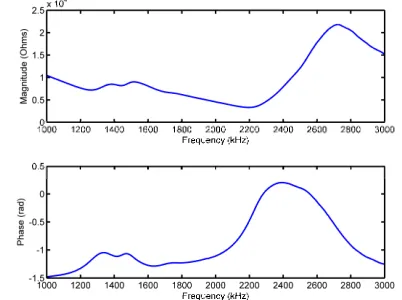
[image:4.612.319.561.266.450.2]The array element operational impedance characteristic of the prototype device was measured in air using a HP impedance/gain-phase analyser and the result is shown in Figure 7. It shows clearly that the main thickness mode resonance occur at the vicinity of the desired array centre frequency (2.2MHz). However, an additional mode, at 1.5MHz, is also observed.
Figure 5. Active layer operational impedance profile measured (in air) using an impedance analyser
B. Surface dilation analysis
The surface dilation characteristics of the array were determined using scanning laser vibrometer, Polytec-PSV400 (Lambda Photometrics, Herts, UK). Figure 6 shows the surface displacement magnitude measured (in air) from a single element. A circle is drawn to highlight the active element that has been excited with a 10Vpp continuous
sinusoidal waveform. It was evident from the laser vibrometry, that the fiber piezocomposite substrate supports an additional parasitic mode. Further experiments were performed to characterise the acoustic properties of the mould material. The salient properties of the 3D print material are provided in Appendix. It is observed that this material property matches quiet closely with the standard hard-set polymer used as an in-fill. Substituting the hard-set with a softer polymer exhibiting increase attenuation, should reduce the contribution of the additional parasitic mode.
Figure 6. Surface dilation measurements in air from a single element (highlighted) under continuous sinusoidal excitation
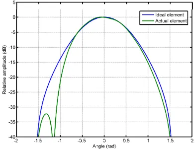
[image:4.612.55.277.328.411.2] [image:4.612.69.270.559.709.2]Figure 7 Predicted element directivity compared with an ideal element
C. Cross talk measurements
[image:5.612.72.268.61.212.2]Electrical cross talk of the active layer was studied using a HP4194A impedance/gain-phase analyzer, the results are presented in Figure 8. Average electrical cross talk for the prototype 2.25MHz design is approximately 59dB, indicating good isolation between elements with no significant variation across the group.
Figure 8. Cross talk measurement carried out in an active layer substrate using a gain-phase analyser
D. Pulse echo characterization (single element)
Pulse echo performance of a single array element was performed with the array directly coupled to a 50mm thick crown glass block. The element was connected to a UTEX UT340 pulser/receiver (reference for utex) and excited using a 100V pulse of 80ns width. The time and frequency domain response of the element is shown in Figure 9.
V. CONCLUDING REMARKS
The design and fabrication of a reduced element count, annular array with fiber composite microstructure has been presented. Work to date has indicated that such an approach provides an efficient and cost effective way of building far-field NDT imaging systems. Future work will extend the philosophy to build an optimized array design, with particular emphasis on spatial distribution of elements and electrical interfacing. This will be reported at a later date.
a
b
Figure 9. Pulse echo impulse response of a single element radiating directly coupled to a 50mm crown glass block,
(a) time domain and (b) frequency domain
APPENDIX
Acoustic properties of the jig and polymer in-fill materials measured at 500kHz
3D print material
CY1301/ HY1300
Vl(m/s) 2479.6 2438.7
Vs(m/s) 1090.9 1149.5
Density(Kg/m3) 1202.87 1149
ACKNOWLEDGMENT
The authors acknowledge Dr. John Mackersie, Mr. Thomas McCunnie, and Mr. Grant Smillie, at the Centre for Ultrasonic Engineering, for their diligence help in manufacturing the prototype devices.
REFERENCES
[1] B.W.Drinkwater, P.D.Wilcox, “Ultrasonic arrays for non destructive evaluation: A review”, NDT&E International, Vol. 39, pp. 525-541, 2006
[2] S.J.Norton, "Annular array imaging with full aperture resolution", Journ Acous. Soc. Am., 92 (6), pp. 3202-6, 1992.
[image:5.612.49.291.339.450.2]