IAC-10-C3.4
THE SUAINEADH PROJECT: A STEPPING STONE TOWARDS THE DEPLOYMENT OF LARGE FLEXIBLE STRUCTURES IN SPACE
M. Vasile
Space Advanced Research Team, University of Glasgow, United Kingdom, [email protected]
M. Cartmell*, F. Z. Dejene**, T. Drysdale†, M. A. Flores**, M. Y. Gulzar**, N. Ismail*, M. U. Khalid**, M. Li**, C. Maddock‡, P. Mallol§, A. Mathieson*, M. McRobb*, J. Öberg**, O. Purcell††, P. Reynolds†, R. Ritterbusch§,
W. Sandqvist**, L. Summerer††, M. U. Tanveer**, G. Tibert§, G. Whyte†, W. Zafar**, J. Zhang**
The Suaineadh project aims at testing the controlled deployment and stabilization of space web. The deployment system is based on a simple yet ingenious control of the centrifugal force that will pull each of the four daughters sections apart. The four daughters are attached onto the four corners of a square web, and will be released from their initial stowed configuration attached to a central hub. Enclosed in the central hub is a specifically designed spinning reaction wheel that controls the rotational speed with a closed loop control fed by measurements from an onboard inertial measurement sensor. Five other such sensors located within the web and central hub provide information on the surface curvature of the web, and progression of the deployment. Suaineadh is currently at an advanced stage of development: all the components are manufactured with the subsystems integrated and are presently awaiting full integration and testing. This paper will present the current status of the Suaineadh project and the results of the most recent set of tests. In particular, the paper will cover the overall mechanical design of the system, the electrical and sensor assemblies, the communication and power systems and the spinning wheel with its control system.
I. INTRODUCTION
A number of future space applications envisage the deployment of large flexible structures in space. From large aperture telescopes to new generation antennas for telecommunication, solar sails to solar power satellites, all require the placement of a light weight flexible structure into space. A space web is the archetype of all flexible structures and can be used as a support to assemble more complex structures. These webs can act as lightweight platforms for the construction of large structures in space without the huge costs of launching heavy materials from Earth. *†‡§**††
The „Suaineadh‟ project, so named after the Gaelic word for twisting, is collaboration between the University of Glasgow and the Royal Institute of Technology in Stockholm. The aim of the testbed experiment is to deploy and stabilize a space web in
*
Mechanical Engineering, University of Glasgow, United Kingdom, Primary contact: [email protected] †
Electrical Engineering, University of Glasgow, United Kingdom, Primary contact: [email protected] ‡
Aerospace Engineering, University of Glasgow, United Kingdom, [email protected]
§
Mechanics, KTH Royal Institute of Technology, Stockholm, Sweden, Primary contact: [email protected]
**
Electronic Systems, KTH Royal Institute of Technology, Kista, Sweden, Primary contact: [email protected] ††
Advanced Concepts Team, European Space Agency (ESA/ESTEC), Noordwijk, The Netherlands, Primary contact: [email protected]
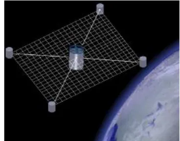
[image:1.612.334.518.473.618.2]micro-gravity by means of the centrifugal forces acting on the spinning assembly which is ejected from the nosecone of the sounding rocket. Controlled web deployment and stabilization will be achieved by an active control method. Operational data will be accumulated visually, via cameras, and by on-board inertial measurement sensors. This data is transmitted via an integrated communications architecture to a recoverable data storage module on-board the sounding rocket.
Fig. 1. Conceptual illustration of the fully deployed ejectable section configuration.
spin-stabilized rocket powered by an Improved Orion Motor with 290 kg of solid propellant. The rocket is capable of taking 40 kg of student experiment modules to an altitude of approximately 100 km. The vehicle has a length of ~5.6 m and a body diameter of 35.6 cm”.1
I.I. History
Since the 1960s, many large, inflatable structures have been launched into space, with the majority of the applications centered on communication antennas, solar sails such as ISAS and Cosmos 1 missions and solar powered satellites. There are two main concepts used for the deployment and stiffening of these structures: one is to use pressurized gas to inflate a internal support structure, and the second is to use spin-stabilization via centrifugal forces2,3,4. The only successful deployment and spin stabilization of a large space structure was the Russian Znamya-2 experiment5 in 1993. The deployment process of the 20 m diameter reflector was driven by an onboard electric motor and a counter-rotating flywheel. In 1999, the deployment of a second, larger 25 m diameter reflector, Znamya 2.5, failed due to a mission operations and software error6,7.
The specific concept of a space-web originates from the Japanese „Furoshiki‟ experiments: a large net or membrane held in tension using radial thrusters or through the centrifugal forces experienced by spinning the whole assembly8,9. In 2006, the deployment of the Furoshiki web by the Japanese ended in a chaotic deployment sequence due to misalignment of the radial thrusters.
I.II. Technical Overview
The experiment objectives are to deploy a space web using centrifugal forces and to stabilize the web once full deployment has been achieved. The total flight duration is
The complete system consists of two parts: the web system that will be ejected from the rocket (CHAD), and a recoverable data storage platform (DaSP). The ejectable payload consists of a central hub section (mother); a square web with a surface area of 4 m2; and four corners masses (daughters) attached to the web. Prior to the deployment the net and corner masses will be wrapped around the hub with an approximate stowage volume of 10 cm3. The total mass of the combined experiment in pre-launch configuration is 5 kg. The volume is 0.0095 m3, with a moment of inertia of 0.0525 kg-m2. The maximum total onboard power is 50 W.
The ejection of the system from the sounding rocket will occur at an altitude of approximately 62 km. An onboard reaction wheel is used to spin the system to the required angular velocity for the deployment sequence to begin. At a safe distance from rocket, the constraints attaching the daughter sections to the mother are
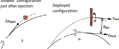
[image:2.612.312.551.196.295.2]released and they begin to deploy due to the centrifugal forces acting on the system. As the web approaches full deployment the reaction wheel is used to prevent recoiling effects and provide stabilization. Data acquisition commences as deployment begins and continues until the receiver onboard the sounding rocket is out of range of the system. The data acquired will be used to validate simulations from previous research studies10,11.
Fig. 2. Conceptual deployment of web after ejection.
The control method uses a reaction wheel to counteract the centrifugal forces as the web approaches full deployment. Once Suaineadh has been ejected, it will follow a pre-determined automated deployment sequence. The reaction wheel will be used to rotate the central hub to a suitable angular velocity for deployment to begin. Once this angular velocity has been achieved, the daughter release mechanism is engaged and the daughter sections will deploy due to the centrifugal forces acting on it. As the deployment nears completion the reaction wheel again rotates the central hub to a sufficient velocity to prevent any recoiling effects and to achieve web stabilization.
The operational timeline is as follows, and is based on GPS data from past REXUS missions.
Prior to launch: All systems on and in pre-launch mode. Instrumentation in stand-by mode.
T+0s: Ignition and Launch, all systems in launch mode.
T+60s: Nose cone ejection, all systems in launch mode.
T+9s: Rocket motor separation, all systems in launch mode (total elapsed time, 69 s).
T+10s: REXUS de-spin, all systems in launch mode (total elapsed time, ~69-79 s).
T+10s: Suaineadh ejection, inertial measurement units activated and begin gathering data. If the correct angular velocity is acquired through the de-spin of the rocket, then no action taken until sufficient separation distance achieved. Otherwise the reaction wheel will alter and correct the angular velocity (total elapsed time, ~79-89 s).
Stowed configuration
T+0s: Deployment sequence, correct angular velocity acquired. Cameras begin accumulating images and daughter release mechanism activates. T+0s: Deployment (duration ~20s), reaction wheel controls deployment; instrument and visual data transmitted to DaSP, stored/transmitted to ground. T+20s: Stabilization: Deployment sequence complete and images of web configuration accumulated and transmitted to DaSP (total elapsed time, 99s).
End of life: Data transmitted to DaSP until loss of link. CHAD impacts ground with no recovery. Expected total mission duration, 358 s)
II. MECHANICAL DESIGN
The structural design requirements were defined on the basis of withstanding the mission loads during the operational lifetime, with predefined loads relating explicitly to mission phases. Fabrication and assembly stresses relate to the manufacture and assembly phases, and environmental loads concern the transportation and handling phase. There are three testing phases, in which vibrations, shock loading, and thermal cycling predominate. Handling and stacking loads, along with pre-flight check conditions relate to the pre-launch phase, and engine acceleration, engine launch vibration, sister mission vehicle separation shock, and yo-yo de-spin loads are all encountered within the launch and ascent phase. Also, pyrotechnic separation from REXUS and web, daughter deployment, reaction wheel operation and thermal environments are key parts of the mission operation phase. In addition to these load/phase relationships the mechanical design was closely driven by the launch vehicle requirements, which can be summarized as follows: spaceflight time 180 s, apogee 100 km, maximum velocity 1.3 km/s, maximum acceleration 20 g, maximum Mach number 4.3, maximum dynamic pressure 290 kN/m2, launch spin rate 4 Hz, vehicle bending moment 11.29 kN·m, major axis is the roll axis, REXUS vehicle length, mass, and diameter are 5.6 m, 100 kg, and 0.356 m respectively.
There are four assumed quantities, namely axial and lateral load factors of 20, and the first axial and lateral natural frequencies should be greater than 25 and 10 Hz, respectively. The environmental conditions under which the system has to work were: building and manufacture 20±5°C, transport down to -30°C, systems integration 20±5°C, and the launch tower at 17±7°C, all within the pre-launch phase. Lift off and re-entry will operate in excess of 110°C, and 200°C, respectively, during launch and flight. These conditions, data, and specifications represent the backdrop against which the mechanical design was undertaken.
It is also important to note that the structure should provide certain system requirements. The sub-system packaging arrangements were such that the
Central Hub to Data Storage interface used a Single D-Sub connection between data storage module and central hub to allow for transfer of power and data. The Data Storage to REXUS interface was to utilize two D-Sub connectors between the data storage module and RXSM to allow for transfer of power and data. The Central Hub and Daughter interface employed Litz wires to connect the CPU onboard the central hub and the daughter sections via guide sleeves on the web. The Central Hub chamber interfaces connect via 15 Pin D-sub connectors. The REXUS ejection mechanism provides a platform for the Central Hub D-sub connector and a second symmetrical D-sub connector platform to ensure a symmetrical ejection moment, and the spring ejection platform has a hole for wire constraint. Protection from the environment, mission loads, and the provision of platforms and attachments for the sub-systems were requirements for the mechanical support to be provided for the sub-systems during the mission lifetime. Web and daughter stowage accommodation on the Central Hub was a critical requirement, as was provision for web deployment and daughter release. It was also deemed necessary to provide a clear field of view for the antennas.
Overall envelope requirements for the system were as follows: length of the central hub 0.24 m, central hub diameter 0.218 m, central hub mass 5 kg, and central hub major axis along the roll axis. Subsystem accessibility was provided by means of removable access hatches for components and batteries, camera apertures were required on the central hub, and antenna mounts were required.
II.I. Structural design
on the system were 49 N in the axial and lateral directions and 12.35 Nm in bending, with x20 load factors to be applied. It should also be noted that the adopted skin thickness of 1 mm was found to give a margin of safety of 64.5. The total structural mass was 1.98 kg. The complete central hub assembly is shown in Fig. 3
Fig. 3. Complete central hub assembly
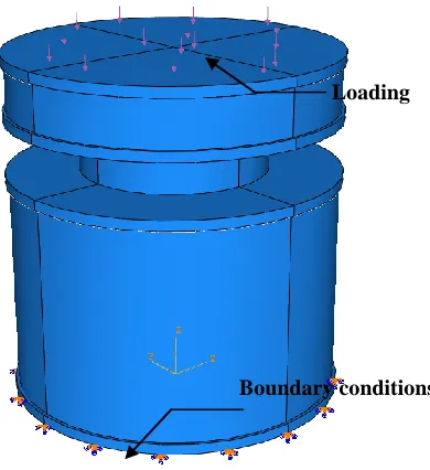
The Abaqus Version 6.7-1 FEA package was used to find the natural frequencies of the central hub structure and to ensure the structure could withstand the loads applied to it during launch. A simplified geometry was generated by removing structurally superfluous attachment details. By reducing the complexity of the geometry a simplified mesh using fewer elements could be created. The elements used in both models were C3D20R (20 node quadratic bricks using 3D stress). The structure was modeled with completely free boundary conditions and the calculated natural frequencies of the first and second axial modes and the first bending mode were found to be 544, 850, and 650 Hz, respectively. A worst case static loading scenario was also modeled assuming that all mass loading of the structure and all components during launch would be applied through the top surface of the top plate, while the bottom plate was fixed in all directions. The loading and boundary conditions for the FEA are shown in Fig. 4.
The forces generated and applied pressure on the upper plate‟s top surface were calculated to be 1155 N and 31 kN/m2, respectively. The FEA model was also used to calculate the structural deformation and stress distribution under loading. The largest displacement was found to be located at the centre of the upper plate and approximately 0.225mm in magnitude. The point which should experience the largest stress was within the structure of the central hub at the conjunction of the upper lateral bars and the upper central plate, where a
stress of 62 MN/m2 was found. This was clearly within the elastic region for this part as the yield strength for Al 6061-T6 bar is 240 MN/m2, giving a safety factor of approximately 3.8. The ejection and D-Sub platforms were modeled with static load conditions similar to those experienced during launch and the loading applied by the central hub was 1155 N, the load distributed equally between the platforms was 385 N, the pressure applied to the ejection platform with a loading area of 0.00636 m2 was 60535 N/m2, and the pressure applied on the single D-sub with a loading area of 0.00381 m2 was 1010 kN/m2. Experimental tests were conducted to find the force required to separate the D-Sub connector and this was found to be a maximum of 7 N. The daughter sections were intended to be attached to the four corners of the web, each containing an inertial measurement unit to provide force data during the deployment and stabilization phases. Estimated mission limit loads were evolved for the daughters at 9.8 N axial and lateral and 0.19 Nm in bending. FEA was also used to calculate likely launch loads on the data storage module, on the basis of a worst case scenario. This led to calculation of the stress at the centre of the daughter data storage box lid, with a value of 14.6 MN/m2, which was well below the limits for the material. The mechanical system was also subject to stringent thermal design criteria, with a wide range of operating temperature limits for the various electrical sub-systems in particular. The widest range to accommodate was with the mission thermal environment operating from extremes of –30°C when being transported to the launch site, to in excess of 200°C during re-entry. Hot and cold case heat sources were established for the mission, and key thermal challenge criteria established for the central
Fig. 4. Boundary conditions and loading.
Loading
[image:4.612.108.260.162.340.2]hub, data storage unit, and daughter sections. Worst case conditions were derived and four different thermal control technologies were considered, namely insulation using aerogel, aluminum foil surfacing, IR radiators, and phase change materials. It was decided that the central hub and data storage units should use insulation, surface finishing, and radiators, and the daughters should use insulation and surface finishing. Required radiator areas were calculated, as follows: central hub 0.0113 m2, data storage 0.000354 m2, and the daughters 0.0000402 m2.
Steady state temperature margins within the hub were calculated as a function of the heat generated, and it was found that the system could be made to be thermally stable and fully protected. It is also important to confirm that stringent testing was adopted for the mechanical system. These tests comprised vibration and shock tests performed on a large laboratory shaker with a test frequency range between 5-7500 Hz. Thermal tests were to be conducted at ClydeSpace Ltd. in Glasgow, and a low friction ice bed surface was planned to be used for testing the daughter release deployment mechanism. Further mechanical tests for capability to withstand launch load have been devised.
II.II. Reaction wheel
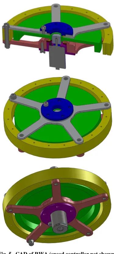
The reaction wheel assembly (RWA) was composed of three major components: a DC brushless motor; the reaction wheel; and the housing. The motor for the RWA is a Faulhaber DC brushless motor 2232-012-BX4 with a separate speed controller type SC2402-P. A CAD model of the RWA is shown in Fig. 5 and the manufactured RWA is shown in Fig. 7. The arms, motor housing and upper bearing lid were made of aluminum alloy while the wheel was manufactured from steel to obtain the required moments of inertia (Ixx = Izz =
681306 g·mm2 and Iyy = 1340718 g·mm2). The total
mass of the RWA was 1.3 kg.
The coupling between the motor shaft and wheel could not be totally rigid since the weight of the wheel would load the shaft far beyond the permissible axial rating of the motor, therefore the wheel was supported on low friction bearings, and a stub-shaft of hexagonal cross-section was mounted on the motor shaft to transmits the motor torque to the wheel whilst also unloading it axially. Once assembled the RWA was mounted on the lower face of the lower central plate within the gas tight lower chamber.
II.II.IReaction wheel testing
The reaction wheel was designed to provide 0.55 N·ms of angular momentum to the web to prevent re-coiling of the web. The reaction wheel assembly was optimized with respect to mass, available electric current, motor torque and motor speed.
[image:5.612.333.520.68.485.2]Fig. 5. CAD of RWA (speed controller not shown).
Two versions of the reaction wheel assembly were manufactured: one simpler test version and the flight version. Ground test showed that the gravity-induced friction in the polymer bearings was too large for the DC brushless motor, so a gravity off-loading system was designed; without gravity, the motor could accelerate fast enough and reach the desired final speed. A further test on a rotating platform (see Fig. 6) confirmed that the wheel accelerated the platform.
II.III. Web design
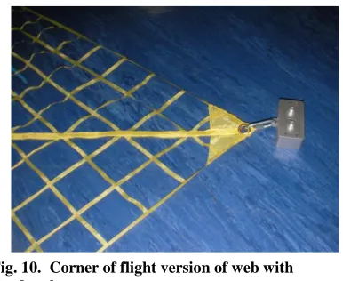
The 2×2 m2 was made from a woven ripstop Nylon fabric, commonly used for hiking tents. Preliminary tests on an air hockey table with a smaller web made from 0.2 mm Dyneema fishing line (Fig. 8) showed that the fishing line was too stiff in bending, resulting in incomplete deployment. Another problem was that the two layers of fishing line, connected by knots, got entangled during deployment, so a single-surface solution was desired. Lightweight spinnaker rip stop fabrics were found to be too stiff, but the hiking-type of ripstop fabrics were soft enough and sufficiently light (36 g/ m2). The tests with the ripstop fabrics were more promising and complete deployment was achieved (see Fig. 9). The actual flight version of the web was
[image:6.612.84.271.68.402.2]manufactured by laser cutting away material from four fabric triangles and then sewing the triangles along the sides together to form the final 2×2 m2 web. The sewn diagonals form sleeves for the electric wiring from the central structure to the corners (see Fig. 10).
[image:6.612.345.531.70.234.2]Fig. 7. Manufactured reaction wheel assembly.
Fig. 8. The 0.6×0.6 m2 fishing line test web fully
deployed by hand (air-hockey pucks represent corner masses).
Fig. 9. Complete centrifugal deployment of the
0.6×0.6 m2 ripstop fabric on the air hockey table.
[image:6.612.342.531.282.419.2] [image:6.612.339.532.451.609.2]II.IV. Deployment mechanism
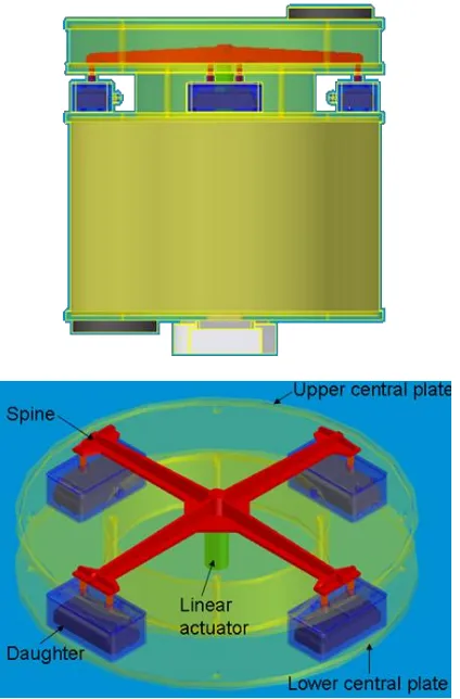
The experiment separation mechanism from REXUS was based on a simple conical compression spring released by a pyrotechnically cut wire, with the two modified D-sub connectors then coming apart as the parts separate. In the system itself the web and daughters were stored within a channel around the central hub. At the beginning of the deployment phase the daughter sections would be released to allow the web and daughters to be deployed by centrifugal force. A dedicated system has been designed to perform these required functions and to withstand the launch environment. This configuration is shown in Fig. 11. The release mechanism specified a linear actuator to push the pins out from the daughter sections. This was chosen for its simplicity and reliability.
The linear actuator was attached to a daughter separation spine with four arms, one corresponding to each daughter section, which have the restraining pins at their tips. Prior to deployment, the daughter separation spines rest on the upper central plate of the central hub with the linear actuator mounted on the upper face of the lower central plate. Before ejection of the central hub from the rocket, no power was transferred to the
linear actuator, for the purpose of safety. Upon ejection, power is sent to the actuator. When the correct angular velocity is achieved the CPU on board the central hub would activate the linear actuator, allowing deployment of the daughters and web to occur.
III. ELECTRICAL AND POWER SYSTEMS The power subsystem of the experiment will be built around a CubeSat 1U battery system, provided by Clyde Space. It consists of two 8.2 V, 1.25 Ah cells, one of which is used as a redundant cell; in this case a single cell would provide ample power to complete the mission objectives. The cells are connected to a Clyde Space COTS electrical power system. The board is a standard PC104 size and is used to monitor battery health, and provide 3.3 V and 5 V regulation. The 3.3 V regulation is not required for any of our components, but it provides a level of flexibility with regards to camera and processor choices. The COTS 1U EPS was modified in order to accept the 28 V, 500 mA battery charging line provided as part of the REXUS umbilical.
A simple power distribution board will be created in order to facilitate the connection of components to the power supply. Litz wire will be used for the data and power connections between the central hub and the daughter sections. This was chosen as both the I2C data line and the power line requires two cores.
The cells selected are high density Lithium polymer batteries, with a voltage of 8.2 V and a rating of 1.25 Ah. The maximum expected current draw during mission operations is approximately 0.7A-0.9A and a quiescent current of 0.4 A. The battery could therefore power the experiment in full operation for a minimum of 83 minutes, which is more than adequate to meet our mission duration requirements.
There are three different voltage lines, plus a ground, for the various components. The CPU and peripherals are fed off a regulated 5 V line. The IMUs require the unregulated supply directly from the battery of 8.2 VDC. The LEDs on the daughter masses will also be connected to the 8.2 V line through a current limiting resistor. The third line is a 28 VDC that will be fed directly from the two batteries (connect in parallel) through a voltage booster.
The experiment platform will connect to the REXUS Service Module (RXSM) via two DSub-15 Cables. These cables will provide control signals (via the RS-422 standard) for launch, start-of-experiment, etc, while also providing all power to the platform in the form of a 28V power line. In addition, a subset of the experiment data will be returned to the RXSM for transmission to earth via these umbilical cables. Connection with the central hub will be made via a Dsub-15 connector which will provide control signals and a conditioned battery charge line. The 27V, 500mA battery charge line must be conditioned to provide 500mA at 5V to charge the
[image:7.612.74.286.77.399.2]batteries onboard the ClydeSpace 1U EPS. This will be done using a 5V Linear Regulator, and the current will be limited to 500mA using an in line resistor (10 ohm). This will then be routed through a power transistor, allowing us to control the charging of the battery and also turn off the battery charge line after ejection.
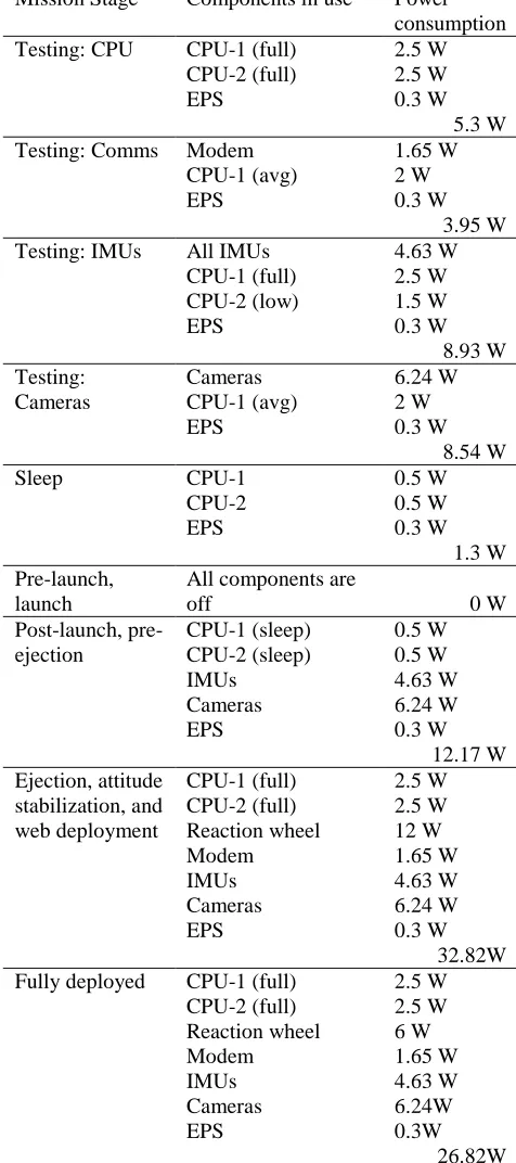
Table 1 gives the total power consumption at each stage of the mission. The maximum power consumption, ~33 W, occurs during the ejection and web deployment. The largest consumer is the reaction wheel which requires 12 W (fed from the 28 VDC line) to spin up the experiment and control the torque during the web deployment. This is also a critical part of the mission, where the maximum number of measurements will be taken, over a short duration (20 s). During sleep mode, the experiment only requires 1.3 W. An umbilical power cable is available by the sounding rocket, and provides a 28 VDC line to charge and maintain the battery level during the pre-launch and testing phases, and, less critically, after launch.
III.I. OBDH and peripherals
The CPUs used are the FreeForm/PCI-104 which uses Xilinx‟s Virtex-5 multi-platform FPGA. There are a number of I/O ports, including two 10/100 Ethernet ports which will be used by the modem, two RS-485 serial interfaces, a high-speed serial connector and 64 single ended or 32 LVDS general purpose I/O. There will be one primary and one backup (secondary) CPU on board the central hub, along with another CPU on the data storage platform onboard the rocket. There is also a specifically designed PIC board to control the reaction wheel (see Section V).
There will be two additional 2 GB SD memory cards – one on CHAD to act as a buffer for the data since the measurement rate is much greater than the wireless link transmission rate. In addition, the data rate during the deployment is skewed to be larger than during the stability phase. The second is on DaSP to store the data for recovery. Industrial temperature grade cards were used in order to reduce the possibility of damage.
IV. COMMUNICATION AND SENSORS
IV.I. Measurements and sensor configuration
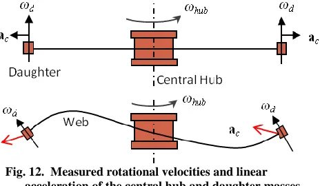
There are three quantities the sensors must measure: linear acceleration, angular velocity and stability of the web. This is done through two main instruments: an inertial measurement unit (IMU), and a camera. There are five IMUs onboard the experiment: one on each of the four daughter sections, and a fifth in the central hub. The IMUs must measure the linear acceleration and rotational velocity of the five points on the web. The data from the daughter IMUs will allow the team to verify and compare against the computer simulations for the controlled deployment of the web. In a perfect deployment, the acceleration vector should be in the radial direction (i.e. centrifugal), and the rotational axis should be normal to the plane of the web (which itself should be confined to a 2D plane). Any disturbances from these ideal values represent either out of plane motion and/or errors or delays in the control (see Fig. Mission Stage Components in use Power
consumption Testing: CPU CPU-1 (full)
CPU-2 (full) EPS 2.5 W 2.5 W 0.3 W 5.3 W Testing: Comms Modem
CPU-1 (avg) EPS 1.65 W 2 W 0.3 W 3.95 W Testing: IMUs All IMUs
CPU-1 (full) CPU-2 (low) EPS 4.63 W 2.5 W 1.5 W 0.3 W 8.93 W Testing: Cameras Cameras CPU-1 (avg) EPS 6.24 W 2 W 0.3 W 8.54 W
Sleep CPU-1
CPU-2 EPS 0.5 W 0.5 W 0.3 W 1.3 W Pre-launch, launch
All components are
off 0 W
Post-launch, pre-ejection CPU-1 (sleep) CPU-2 (sleep) IMUs Cameras EPS 0.5 W 0.5 W 4.63 W 6.24 W 0.3 W 12.17 W Ejection, attitude stabilization, and web deployment CPU-1 (full) CPU-2 (full) Reaction wheel Modem IMUs Cameras EPS 2.5 W 2.5 W 12 W 1.65 W 4.63 W 6.24 W 0.3 W 32.82W Fully deployed CPU-1 (full)
CPU-2 (full) Reaction wheel Modem IMUs Cameras EPS 2.5 W 2.5 W 6 W 1.65 W 4.63 W 6.24W 0.3W 26.82W
[image:8.612.64.302.79.615.2]12). The limitation is that the actual position is never directly measured. It is hoped that the photos will help correlate the measurement data from the IMUs primarily in detecting if there is any out of plane motion. A second gyroscope on the central hub will be used to measure the torque of the reaction wheel, used in the controlled web deployment, through feedback control loop.
Fig. 12. Measured rotational velocities and linear acceleration of the central hub and daughter masses, and the effect of out-of-plane disturbance on the web.
The ratio of the masses of the corner units to the central hub has a direct influence on the spin rate and stability. Since the overall experiment mass was limited to 5 kg, the corner masses had to be kept as light and small as possible, with a maximum of 0.03 kg. The IMU chosen was the MEMSense nanoIMU, which combines three sensors: a gyroscope (with a range up to 300 deg/s), accelerometer (±2g) and magnometer, plus an analogue-to-digital converter. The IMU uses an I2C interface to connect to the main CPU, and will be directly connected to the central hub via wires that are sewn into the web structure. Each unit measures 4.35 × 2.28 × 1 cm, and weighs 20 grams. The maximum sample rate is 50 Hz, or 50 measurements per second.
Four cameras will be mounted, equally spaced around the central hub, each facing a daughter section (i.e. corner) of the fully deployed web. The cameras, Aptina MT9T111 System-On-A-Chip CMOS Digital Image Sensors, were donated by Sony-Eriksson, and are in use in their mobile phones. The size and advanced technology of these sensors make them ideal for use in this experiment, as the central hub is only 22 cm in diameter. Each camera measures 10.05 x 10.05 x 2 mm, and is mounted on a custom-made PCB designed in-house at the University of Glasgow. Each image has a maximum resolution of 2048×1536 pixels, with a frame rate of 15 fps. The concern in the effectiveness of the cameras was the large difference in background contrast and light intensity. As the web itself is almost invisible to the cameras, coloured LEDs were added to each daughter section in order to more easily identify the position of each daughter mass. The main role of the
cameras is to detect any out-of-plane motion, which will show as vertical displacement in the photos.
Every measurement is tagged with a timestamp by an onboard clock in the CPU, in addition to time tagging within the sensors themselves.
IV.II. Data collection and transmission
Data management is a critical element of the mission design. The measurements are taken and recorded onto onboard memory on the central hub. The data is then re-packaged and sent, via a wireless link, to a data storage module (DaSP) onboard the rocket. All received data is stored on a recoverable data service module designed and operated by the REXUS team. In addition to this, each experiment is allocated a portion of a low data-rate downlink from the rocket to the ground station in Esrange. While it is only capable of transmitting a small portion of the measurements, it serves as a backup in case of problem or failure with the recovery module.
The data management software onboard the central hub must be able to receive input data from two different sources: digital data from the IMUs, and images from the cameras. The camera will output compressed still frames in JPG format. The data needs to be combined, and re-encoded with a time stamp from the main CPU, plus synchronization bits, message ID and checksums in order to verify the entire data packet was received at the receiver on the REXUS platform. For the communications side, the data also include error correction and detection overhead. Once on-board REXUS, the data is stored on the SD memory cards for retrieval and analysis later. A portion of the data will be transmitted to the REXUS service module, and transmitted via downlink to Esrange (SSC ground station located in Kiruna Sweden). Due to the low data rate, only a small portion of the data will be transmitted (~2.5%). The data will therefore have to be sorted. A sorter will look at the timestamps and device IDs from each package transmitted, and select every nth
measurement (approximately every 10th reading) from each IMU to be transmitted down. Message packets will have to re-divide since the requirement for the REXUS-GS downlink is that each word must be a maximum of 24 bits (15 + 9 bits overhead); with 3 ms interrupt spacers between each word. Synchronization and check-sums will be added to verify the data transmission, as well as EDAC protocols. The data will be collected in real-time by a laptop at the GS.
packet was deemed overly complicated. Given that the priority data measurements are taken at a rate of 50 Hz (IMUs), a percentage of the data can be lost while still maintaining enough collected sample points to satisfy the mission requirements.
The main criteria for selecting the centre frequency and bandwidth for the Suaineadh-REXUS link are to minimize any interference with other antennas, and free use of the band (i.e. reduce costs). Therefore the link will use the IMT UHF band around 900 MHz. This band is not usually allowed for operation in Europe as it is in use by mobile GSM operators. There are however, no other unlicensed bands available that would not interfere with other links on REXUS-8. The IMT band at 900 MHz is widely used in North America, and hence a number of qualified off the shelf components are available. The frequency allocated to Suaineadh by the Swedish Telecom Authorities is 915.5 MHz, with a bandwidth of 1 MHz (i.e., 915–916 MHz). There are a large number of antennas on-board REXUS and it is important to avoid or minimize interference.
The total experiment will collect 1.62 GB of data over 80 s, and transmit this at a rate of 1 Mb/s from CHAD to DASP over an estimated link duration of 180 seconds. The data is prioritized however, such that the IMU data will be sent first over the initial 100 s along with 2 photos, with the remaining data over the remaining link time.
IV.II.IModem
The modem is chosen is the Microhard IPn920 Wireless Module. The development package includes: a radio modem, rubber duck antenna and cables, and a transceiver and receiver. The modem operates within the 902-928 MHz band, with the option of user-defined hopping patterns. This modem offered the highest data rate (1.2 Mbps) while meeting the size and mass requirements of the central hub. The maximum transmit power of the modem is 1 W, with 32 bits of CRC, and selectable Forward Error Correction with retransmit. The OEM modem weighs 19 grams, and measures 32x51x6.35mm. The antenna connection is type MMCX, and connected to the CPU via a 60-pin OEM interface. The development package includes an interface board which can be used for testing and programming independently of the CPU of the actual experiment. As the team is composed of many different departments in many physically different locations, this was very useful in the initially testing phase.
IV.II.IIAntenna
To ensure successful data transmission, the choice of antenna was crucial. As both the rocket and the experiment are spinning through the duration of the link, with a high degree of uncertainty in the exact relative position and velocity, the total antenna coverage
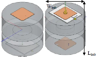
[image:10.612.323.527.135.261.2]should be as omni-directional as possible. This rotation also impacts the beam polarization; therefore the antennas should be circularly polarized. Lastly, they must fit within the structure of the central hub, and DaSP.
Fig. 13. Schematic of central hub with dual-patch antennas (top patch on left, bottom patch on
right).12
epoxy adhesive has a dielectric constant of ~3.2. The patches are 87 mm square for the top patch and 79.95 mm for the bottom patch (with the brass hook), minus the corner chamfers. The total height is 1.524 mm.
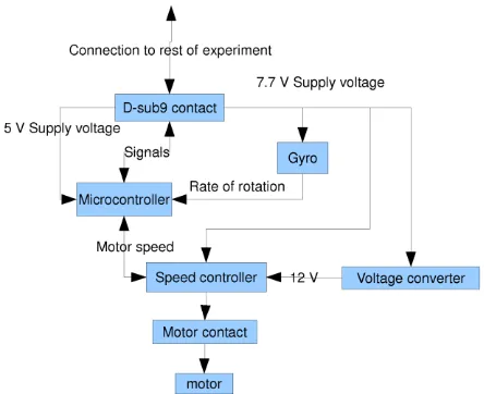
V. WEB STABILITY CONTROL SYSTEM The role of the web stability control system is to ensure that sufficient angular momentum is transferred from the central hub to the deploying web in order to prevent re-coiling of the web around the central hub. Once fully deployed, the reaction wheel will continue spinning to stabilize the plane web. This strategy assumes that the centrifugal forces due to spinning around the main spin axis will dominate other forces, so tumbling around other axes must be minimized.
In the early phases of deployment, the RWA must provide torques to counteract the de-spinning of the central hub. The control system only uses the information from the gyro on the central hub for the calculation of the required torque,13 so no measurements from the corners of the web are required (see Fig. 14).
The development of the control system PCB started in November 2009,14 and was completed in June 2010.15 The PIC has been programmed with the control law from Gärdsback and Tibert13, and initial tests have been successfully completed.
VI. CONCLUSION
This paper has outlined the design, integration and initial testing for a very low cost (under £10k), student designed experiment of a deployable space web. The project is currently in the integration and testing phase, and scheduled to launch in the REXUS 2012.
This project has a number of interesting and innovative aspects: to test and verify research and simulations conducted over the past 5 years by two difference research teams (University of Glasgow and KTH) on spin control methods for both deploying and controlling the stability of a flat structure in space is a critical step in advancing the field of deployable structures. In addition, a number of specifically developed hardware components were generated, such as the patch antennas, reaction wheel, control algorithm
and the web itself. The knowledge and experience gained from these can be used for other small cubesat missions within and outwith the universities. Lastly, the experiment has seen collaborations between two universities and 8 different departments/groups, and a number of small and large companies and research organizations, such as ESA. This level of cooperation and organization required is extensive and complex, but necessary in order to gain valuable experiment results in the field of space research.
VII. ACKNOWLEDGEMENTS
The authors would like to thank the many people at MORABA/DLR, SSC/Esrange, and the ESA Education Office for their technical support and advice during the REXUS-8 campaign. In addition: ClydeSpace for the donation and support of the EPS system, Dr Giorgio Magistrati, Head of On-Board Computers & Data Handling Section at ESTEC, and Dr Marco Molina, Head of the Thermo-Mechanical Division, Carlo Gavazzi Space for help on issues relating to thermal analysis, and corresponding software.
Transmit power Ptx 1.00 W
0.00 dBW
Transmit gain Gtx 0.00 dBi
Receive gain Grx 0.00 dBi
Center frequency fc 915500000.00 Hz
Bandwidth BW 1000000.00 Hz
Modulation (BPSK) M 2.00
Forward error correction code rate FEC 0.50
Data rate Rusr 1000000.00 bps
Maximum modem RF data rate Rmax 1200000.00 bps
Maximum range (estimated) r 1000.00 m
[image:11.612.314.536.74.255.2]Free space loss FSL -91.67 dB
Additional system losses (cable, connector) Lsys -6.00 dB
Estimated system noise temperature Tsys 700.00 K
28.45 dBK
Boltzman constant k 228.60 dB
Noise power N=kTB 317.05 dB
Ratio of error per bit to noise Eb/No 42.47 dB
Carrier to noise ratio C/No 102.47 dB
Receive power Prx -67.67 dBm
Manufacturer receiver sensitivity (at 1.2 Mbps) Prx_min -105.00 dBm
[image:12.612.78.532.70.190.2]Margin 37.33 dBm
Table 2. Link Budget for communication between the central hub (CHAD) and DaSP
1
REXUS/BEXUS – Rocket and Balloon Experiments for University Students, http://www.rexusbexus.net/, retrieved 01 Sep 2010.
2 Schuerch, H. U. and MacNeal, R., Deployable centrifugally stabilized structures for atmospheric entry from space,
NASA CR-69, July 1964. 3
Lang, W. E. and Honeycutt, G. H., Simulation of deployment dynamics of spinning spacecraft, NASA TN-D-4074 Aug. 1967.
4 Hedgepeth, J. M., “Dynamics of a large spin-stiffened deployable paraboloidal antenna”, Journal of Spacecraft and
Rockets7(9), pp. 1043–1048, 1970, doi: 10.2514/3.30100.
5 Melnikov, V. M. and Koshelev, V. A., Large space structures formed by centrifugal forces, 1st Edition, Vol. 4 of
Earth Space Institute Book Series, Gordon and Breach Science Publishers, Amsterdam, The Netherlands, 1998, pp. 21–61.
6 Shpakovsky, N., “Space Mirror,” The TRIZ Journal (online journal), Vol. 7, No. 6, 2002,
http://www.triz-journal.com/archives/2002/06/e/index.htm, retrieved 01 Sep 2010.
7 Syromyatnikov, V., SRC-Space Regatta Consortium, Znamya-2.5 intermediate experiment in space,
http://src.space.ru/inform-e.htm#4, retrieved 01 Sep 2010.
8 Nakasuka, S., Aoki, T., Ikeda, I., Tsuda, Y., and Kawakatsu, Y., “Furoshiki Satellite – a large membrane structure as a novel space system”, Acta Astronautica48(5–12), pp. 461–468, 2001.
9 Nakasuka, S., Funase, R., Nakada, K., Kaya, N., and Mankins, J. C., “Large membrane Furoshiki Satellite applied to phased array antenna and its sounding rocket experiment”, Acta Astronautica58, pp. 395–400, 2006.
10
Tibert, G. and Gärdsback, M., Space Webs, KTH Engineering Sciences, Royal Institute of Technology, ESA ACT Ariadna Final Report 05/4109a, 2005.
11 McKenzie, D., Cartmell, M., Radice, G. and Vasile, M., Space Webs, University of Glasgow, ESA ACT Ariadna
Final Report 05/4109b, 2005.
12 G. W. M. Whyte, C. Murray, C. Maddock, M. Vasile, T. D. Drysdale, “Integrated 915 MHz Dual-Patch Circularly Polarized Antenna for Suaineadh Space Web Experiment”, IEEE International Symposium on Antennas and Propagation & CNC/USNC/USRI Radio Science Meeting, Toronto, Canada, July2010
13 Gärdsback,M. and Tibert, G., “Optimal Deployment Control of Spinning Space Webs and Membranes”, Journal of
Guidance, Control, and Dynamics32(5), pp. 1519-1530, 2009, doi: 10.2514/1.42203. 14
: Zerihun Dejene, F., Zhang, J., Li, M., Alaniz Flores, M., Usman Khalid, M., Usman Tanveer, M., Yousaf Gulzar, M. and Zafar, W., “Rexus-Suaineadh Satellite Experiment”, Final report in course IL2213, KTH ICT School, December 2009,.
15