Design and Development of Deployable
Self-inflating Adaptive Membrane
Thomas Sinn1 and Massimiliano Vasile2
Advanced Space Concepts Laboratory, University of Strathclyde, Glasgow, United Kingdom
Gunnar Tibert3
Department of Mechanics, KTH Royal Institute of Technology, Stockholm, Sweden
Space structures nowadays are often designed to serve just one objective during their mission life, examples include truss structures that are used as support structures, solar sails for propulsion or antennas for communication. Each and every single one of these structures is optimized to serve just their distinct purpose and are more or less useless for the rest of the mission and therefore dead weight. By developing a smart structure that can change its shape and therefore adapt to different mission requirements in a single structure, the flexibility of the spacecraft can be increased by greatly decreasing the mass of the entire system. This paper will introduce such an adaptive structure called the Self-inflating Adaptive Membrane (SAM) concept which is being developed at the Advanced Space Concepts Laboratory of the University of Strathclyde. An idea presented in this paper is to adapt these basic changeable elements from nature’s heliotropism. Heliotropism describes a movement of a plant towards the sun during a day; the movement is initiated by turgor pressure change between adjacent cells. The shape change of the global structure can be significant by adding up these local changes induced by local elements, for example the cell’s length. To imitate the turgor pressure change between the motor cells in plants to space structures, piezoelectric micro pumps are added between two neighboring cells. A passive inflation technique is used for deploying the membrane at its destination in space. The trapped air in the spheres will inflate the spheres when subjected to vacuum, therefore no pump or secondary active deployment methods are needed. The paper will present the idea behind the adaption of nature’s heliotropism principle to space structures. The feasibility of the residual air inflation method is verified by LS-DYNA simulations and prototype bench tests under vacuum conditions. Additionally, manufacturing techniques and folding patterns are presented to optimize the actual bench test structure and to minimize the required storage volume. It is shown that through a bio-inspired concept, a high ratio of adaptability of the membrane can be obtained. The paper concludes with the design of a technology demonstrator for a sounding rocket experiment to be launched in March 2013 from the Swedish launch side Esrange.
Nomenclature
BEXUS = Balloon-borne EXperiments for University Students DLR = German Aerospace Center
ESA = European Space Agency
EVA = Extra Vehicular Activity
IN-STEP = In-Space Technology Experiment Program (NASA)
1 PhD-Candidate, MSc, Advanced Space Concepts Laboratory, University of Strathclyde, 75 Montrose Street, G1 1XJ, Glasgow, UK, AIAA Student Member, [email protected]
2
Reader in Space System Engineering, PhD, Advanced Space Concepts Laboratory, University of Strathclyde, 75 Montrose Street, G1 1XJ, Glasgow, UK, AIAA Senior Member, [email protected]
2 PET = Polyethylene Terephthalate
REXUS = Rocket-borne EXperiment for University Students SAM = Self-inflating Adaptive Membrane
SEDS = Students for the Exploration and Development of Space SNSB = Swedish National Space Board
StrathSat-R = Technology Demonstrator for SAM onboard REXUS13/14 TRL = Technology Readiness Level
I.
Introduction
PACE vehicle size is nowadays mainly governed by launch vehicle dimensions. The use of deployable structures became necessary due to their low stowage and high in-orbit volume. For the success of future space missions involving large space structure, the development of new deployable structures and the improvement of current designs are of great importance. Applications can be easily envisioned through truss structures, masts, crew quarters, transport tunnels, large solar arrays, solar concentrators, solar sails or antennas.1 A valuable option for these large ultra light structures is the exploitation of inflatables. Reasons for the use of inflatable structures range from their low cost over exceptional packaging efficiency, deployment reliability, low stowage volume to low weight. Despite the fact that there has been no major leap on inflatable structure in space since the IN-STEP Inflatable Antenna Experiment2 in 1998, research has been undertaken in various institutions all over the world in the field of inflatable structures;3-6 new membrane materials have been discovered that can withstand the space environment, advanced simulation tools were developed that capture the highly non-linear behavior of the inflation process and rigidization techniques have been investigated making the structure non-reliant on the inflation gas after deployment.7-9 Especially the aspect of the low manufacturing costs makes inflatable structure a prestigious field for university based research and projects or small satellite missions. Various space structures are serving just one specific purpose in space systems nowadays. By developing a structure that can adapt itself to various mission stages, the flexibility of the entire mission can be enhanced.10-12 With applying smart structures, the spacecraft can easily adjust itself to the space environment and expensive on-ground simulation to verify the accuracy of the structure when subjected to the harsh space environment are not necessary. By integrating actuators, sensors and controller into a thin plate, a smart membrane is developed. These kind of smart membranes have various applications in space systems. Examples of these structures range from telecommunication over earth observation to human space missions. For example, these membranes can form antennas or concentrators which are able to adjust their focal point autonomously depending on their orientation towards the sun or their position in orbit. By using the membrane as a substructure for a solar sail, attitude control of the solar sail can be achieved by changing the shape of the structure and therefore varying the area subjected to the solar wind. This area change will result in an attitude change of the space craft. Such a smart structure could even make manned space mission more affordable due to its versatility. Examples range from sun shields for extraterrestrial greenhouses or simple to transport antennas or shelters. Depending on the size, a single astronaut could easily carry such a structure to a specific location in small storage containers and then release them wherever they are needed, e.g. during an extra vehicular activity (EAV) or a space walk on Moon or Mars.
II.
Design of the Self-inflating Adaptive Membrane (SAM)
In the following the idea behind the bio-inspired membrane will be discussed, followed by the principle of the passive trapped air inflation technique. A set up of LS-DYNA inflation simulation will be outlined together with manufacturing techniques of the actual bench test specimen which were tested under vacuum conditions. At the end of this chapter, the design of a technology demonstrator for a sounding rocket mission which is to be launched in March 2012 is presented.
A. Bio-inspired structure
The flexibility of the spacecraft can be increased by enabling the structure to change its shape and therefore adapt to different mission requirements in a single structure. Such a smart space structure which uses the principle of nature’s heliotropism is described here. Heliotropism is the growth or movement of an organism towards the direction of the sunlight.13 By changing the turgor pressure between adjacent cells in the plant’s stem, called motor cells, the stem of the plant flexes.14 Due to the simplicity of the principle, the movement due to pressure change seems perfect for the application on deployable space structures.
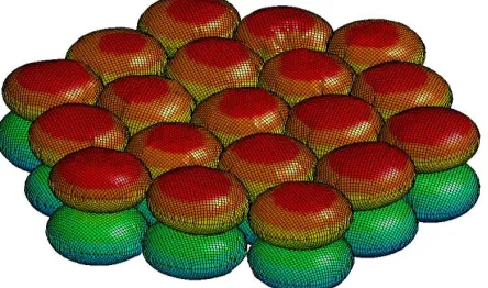
The entire adaptive structure is made of spherical cells that are inflated using residual air inflation which is described in the chapter below. The initial spheres are fabricated with similar volume and internal pressure after deployment. By changing the pressure between two adjacent cells, the volume of one of them increases, the other decreases. With this local volume change, the shape of the global structure will change. A single actuator unit consists of two inflatable spheres and a piezoelectric micro pump in between to establish a pressure difference. Figure 2b shows how the shape of the initially flat membrane changes with the volume change of two neighboring cells. A great importance of this project is given to the scalability of the structure, consequently a spherical base element is chosen as the smallest re-occurring element of the Self-inflating Adaptive Membrane (see Figure 1). By joining these spherical elements together, the size of the whole structure can be easily expanded. It is envisioned to use hundreds of these elements to create space structures or spacecraft subsystems of every imaginable size. The equilibrium shape of the membrane can be designed in every conceivable shape by changing the size of the spherical elements before even actuated. Figure 2a shows an example of a curved initial membrane in equilibrium without any actuation. The basic spherical structures are manufactured by joining two metalized polyethylene terephthalate (PET) films together; the PET is welded around the circumference. By inflating the structure a spherical structure close to an ellipsoid will form. For an actual space mission it is envisioned to use Kapton instead of PET as a membrane material due to its high resistance against ultra violet light compared to the polymer material.15
Another advantage of this concept is its high reliability after deployment against micro meteorites or space debris impacts.16 The penetration of high velocity particles through one of the inflated pillows will have minimal impact on the performance of the whole structure due to the great amount of separated air pockets over the entire structure.
B. Self-inflating Structure
Minimal complexity of the deployment sub structure and deployment process is of especially great importance for small satellites due to their volume and mass constraints. Current designs mostly require a complex mechanism or voluminous secondary structures for their deployment mechanism.17 For this reason, the design approach undertaken in this research focuses on a passive deployment system without the need of any manual control. The basic idea is to use residual air inflation as a deployment mechanism. The structure can be easily folded in a very low stowage volume if the flat structure was manufactured under sea-level conditions. By subjecting the structure to space conditions, especially vacuum, the pressure difference between the inside of the structure and
a) b)
Figure 2. a) Pre-deformed membrane b) Shape change of flat membrane induced by volume change of neighboring cells
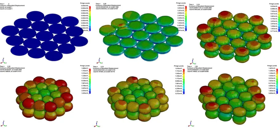
[image:3.612.73.236.76.195.2]Figure 3. Deployment simulation on array of 19 spherical unit pairs
[image:3.612.91.537.331.437.2] [image:3.612.322.544.550.681.2]4
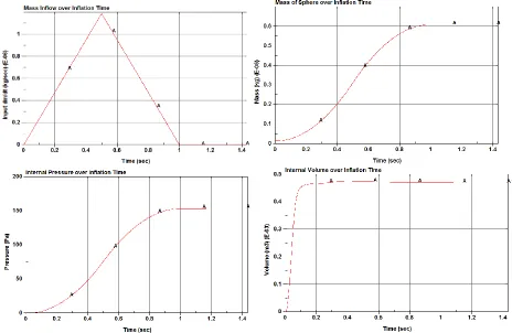
the environment will inflate the structure. LS-DYNA™ simulations were performed to determine how much initial residual air is needed to obtain the desired shape in vacuum conditions. The result of the residual air simulation by using the control volume method for single spherical elements with a diameter of 14.5cm can be seen in Figure 1. Figure 3 shows the LS-DYNA™ deployment simulation for an array of nineteen spherical unit pair elements. If one or several inflatable spheres are deflated, the array structures will ensure the integrity of the structure. The initial shape and the folds were modeled in the LS-DYNA pre-processor LS-PrePost. For the control method approach a mass flow rate into the enclosed structure needs to be defined. The inflation is triggered by the increased volume by subjecting the structure to a reduced pressure environment as it exists in space. With this approach there is no actual mass flow of inflation gas into the structure. Further research will be undertaken in developing tools for LS-DYNA and experiments to predict the residual air inflation method in vacuum conditions and the initial residual air mass more accurately. By using the control volume method and applying it to the entire structure, a similar inflation characteristic then the residual air method can be achieved because the entire volume will expand without starting at one specific initial point. The mass flow required for the control volume method was calculated by employing simple sphere geometrics and thermodynamic equations by using the assumption of dealing with an ideal gas. The volume of one inflatable sphere is approximately 1596 cm3 by considering a perfect sphere. Simulations showed that by inflating from the initial flat shape with 14.5cm diameter, an ellipsoid with a volume of roughly 500cm3 will form after full inflation. Taking this 500cm3 as the desired fully inflated volume in space and by assuming a pressure difference between the inner structure and vacuum environment of 100Pa (0.001bar), the trapped gas mass is in the order of 595x10-9kg. A triangle shaped mass flow characteristic was selected over the rectangular progression because of the nature of the residual air inflation method which will probably start slowly, leading to a maximum and slowing down afterwards. The triangular mass inflow can be seen in Figure 10 of the appendix, it is obvious from the volume plot that the full inflated volume is achieved after a fraction of the inflation time (Figure 11), while the pressure build up requires the length of the entire inflation process. The pressure increase is due to the defined triangular mass inflow, it needs to be verified if the actual pressure behaves the same way during the bench test. For further research it is envisioned to add a pressure sensor in the inflating probe while subjected to vacuum to verify the correctness of the LS-DYNA pressure plot (control volume method).
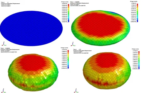
[image:4.612.74.530.383.593.2]Figure 4 shows a sequence of deployment simulation results for an array of 19 pairs of spheres with contours of the resultant displacement. It can be seen that while the spheres are inflating the overall diameter of the structure becomes smaller. The fourth and fifth image in Figure 4 show that the array is getting compressed first but springs back to a wider more flexible shape afterwards in image six. The first three images are taken with 0.1seconds apart, the last three with 0.35seconds apart. The reason for this is that the spheres the volume increases significantly in a fraction of the second which results in a dynamic motion of the entire structure in the time after inflation.
The available inflatable volume can be further increased by either adding a coating that undergoes a phase-change in vacuum conditions18 or a powder that sublime into gas to provide additional vapor pressure to the inflating structure.19
C. Fabrication
To create the inflatable structure for the adaptive membrane, various fabrication methods were investigated. It was identified in the early stages that heat sealing would be the best option to create seams to join the materials. The inflatable specimens are created by joining two flat sheets of polymer together around their circumference. Heat is applied evenly to the seal area, minimizing the material deformation due to intensive heat. The pressure applied on the sealing tool needs to be applied evenly as well, ensuring that the seal quality is not compromised.
Various prototypes of polymer films were tested under vacuum conditions. These included metalized polyester (commonly used in rescue blankets), kapton polyimide film, polyethylene, mylar, teflon film, solarfilm and solartex. Solarfilm and solartex are polypropylene films that are commonly used as a skin material for model aircrafts. Vacuum inflation tests showed that most of the specimens indeed inflated but some didn’t stay inflated due to seam failures. As the test samples were created by hand, it was difficult to create seams evenly around all edges. It was concluded that a more automated process was required, allowing for even seals to be created. A more automated production process would also result in quicker manufacture times. The deformation, however, is highly dependent on the seal quality. Figure 5 shows the vacuum inflation of a circular specimen manufactured of 20micron Mylar. A process has been developed using a circular metal ring tool with an inner diameter of 14.5cm. The circular ring is getting heated externally either by an equally applied heat source from top or a heating wire wrapped around the metal ring tool. With this improved manufacturing technique it is possible to manufacture reliable spheres fast. This improvement is of special interest for the manufacturing of even
bigger arrays of spheres.
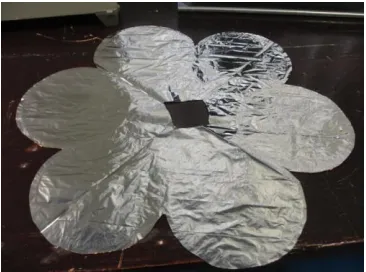
The material polyethylene terephthalate (PET) gold aluminized on one side and silver aluminized on the other side showed the best seam quality while inflatated in the vacuum chamber. This material can commonly be found in rescue blankets, also known as space blankets. The gold side has the best heat welding properties and was therefore chosen as the internal surface of the spheres, making the entire outside surface silver reflective. The inflation test showed seam consistency through various inflation tests. Figure 6 shows a bench test prototype with 6 inflatable spheres arranged around a central cut out point. The structure shown in Figure 6 has a diameter of 33.5cm.
D. Storage and folding patterns
In order to achieve the deployment of such a large self deploying structure, storage options and folding patterns needs to be investigated very verily. The flat nature of the un-inflated membrane enables the use of highly efficient origami folding techniques to decrease the storage volume. The two folding patterns investigated in this paper are the star (Figure 7a) and the Miura-ori folding pattern (Figure 7b). The star folding pattern is mostly used in the folding of solar sails. This folding pattern consists of valley and mountain folds rectangular arranged with a cross point at the edges. Symmetric deployment from one central point can be achieved with this folding pattern. The corners of the initial rectangular sheet are longer after folding then the edges in-between the corners. The extensive material can be wrapped around on central point for storage. The Miura-ore fold20 on the other hand can be packed into a very compact volume with its thickness which is only governed by the thickness of the material. The entire Miura-ori folded membrane can be easily unfolded by pulling on two corners of the membrane and likewise folded again by pushing the corners back together. This unfolding scheme can also be applied between just two folds of the Miura-ori fold which results in an unfolding of the entire structure. By applying this folding pattern to the multiple
Figure 6. PET Prototype with 6 spheres racially aligned
[image:5.612.71.281.159.277.2] [image:5.612.352.535.401.537.2]6
sphere structure of the Self-inflating Adaptive Membrane the deployment reliability of the entire structure is increased greatly because even if a few of the spheres don’t inflate, the other functional folds force a flat deployment with the Miura-ori fold. At the moment, the Miura-ori fold technique is recommended for the self-inflating adaptive membrane but bench tests and the sounding rocket experiment have to prove if this folding option is really the optimum solution for the Self-inflating Adaptive Membrane.
E.
Sounding Rocket Experiment StrathSat-R
To serve as a technology demonstrator for the Self-inflating Adaptive Membrane concept, a sounding rocket experiment was developed. The experiment has the purpose of validating different inflation deployment techniques in space conditions.
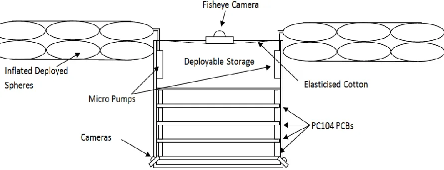
Two free-flying units of the size of a 1U cube satellite (10cm corner length) will be deployed shortly before apogee. The first cube satellite will deploy the Self-inflatable Adaptive Membrane (SAM) described in this paper (see Figure 8). The second cube satellite will deploy a cone that can be used as a deorbiting device for cube satellites.21 The two free-flying units will get ejected from the rocket in approximately 80km altitude with an apogee of around 86km. After achieving a necessary distance, the free flying units will deploy their inflatable structure. SAM will inherent forty percent of the cube satellite’s structure which should lead to a membrane diameter of 72.5cm once deployed with a packing efficiency of thirty percent. The diameter of the spherical elements is chosen to be 14.5cm to fit the storage box of 10cm by 10cm in the central sphere. With the opportunity of launching the experiment onboard a sounding rocket, SAM can show its capabilities in a vacuum environment without the perturbation of gravitational forces. Simulations showed that the deployment at atmospheric conditions varies compared to simulations undertaken in space conditions. The experiment has two main stages, the deployment phase and the adaptive phase.
a) b)
[image:6.612.131.501.148.293.2]
Figure 7. a) Star folding pattern applied to the bench test prototype b) Miura-ori folding pattern
[image:6.612.81.527.388.559.2]After ejection out of the rocket is achieved, deployment gets initiated by reducing the pressure in the inflatable storage compartment. The pressure will get decreased to ambient pressure at roughly 80km altitude. The deployable structure of SAM consists of two layers of spherical cells that are deployed by using the expansion of trapped air in the spheres when subjected to vacuum (space) conditions. The two layers of spheres are manufactured out of 12micron reflectively aluminized PET. Each cell
is manufactured by heat welding circular sheets of aluminized PET together. To ease the deployment of the adaptive membrane from the deployable storage box, an elasticized cotton film was added to help deploying the adaptive membrane after ejection of the cube satellite from the rocket module.
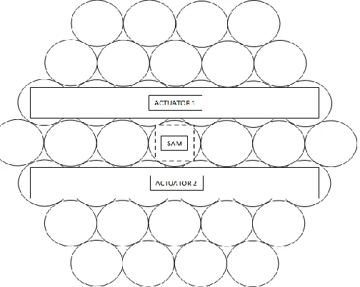
Mp6 micro pumps from Bartels Mikrotechnik GmbH (Dortmund, Germany) are used to change the pressure between two adjacent cells, one in the top layer, and one in the bottom layer. There will be two pumps mounted to the inside wall of the deployment storage (see Figure 8). The deployed state of SAM can be seen in Figure 9. The rows of spheres closest to the sides of the cube are joined to form one big actuator. The micro pumps will pump the residual air from the bottom to the top layer of Actuator 1 to lift up the up side and respectively from the bottom to the top layer of Actuator 2 to lift up the down side of SAM. The control software will alternate
between the actuation of Actuator 1 and Actuator 2 which will result in a flapping movement of the entire structure. During the deployment and adaptive phase, images from three cameras on the structure will be taken and stored on board the free-flying unit. The ejected cube satellites will be recovered after reentry. In December 2011, the experiment got selected for the upcoming REXUS/BEXUS campaign with the Self-inflating Adaptive Membrane experiment. The launch of the REXUS13/14 sounding rocket is scheduled for March 2013. The German Aerospace Center (DLR), the Swedish National Space Board (SNSB) and the European Space Agency (ESA) offer the opportunity to launch experiment onboard sounding rockets twice a year with the REXUS/BEXUS program.22 The authors’ experience on the last REXUS experiment SUAINEADH,23
which had the purpose of deploying a web in microgravity, will enhance the scientific return of the Self-inflating Adaptive Membrane mission.
III.
Conclusion
This paper should give a general overview on the design and the principle behind the Self-inflatable Adaptive Membrane (SAM) concept. The design presented is an ultra-lightweight, fully autonomously deployable, expandable due to its modular shape, resistant against micro meteoroids and space debris impacts because of its separated spheres and adaptable to various environmental conditions. The main difference of the presented structure is the cellular bio-inspired approach. The structure consists of trapped air inflating spheres with neighboring cells connected by micro pumps. The local pressure change introduced between two neighboring cells results in a global shape change. LS-DYNA™ was used to simulate the deployment of one single sphere and the entire bench test structure consisting of nineteen pairs of spheres using the control volume method. The biggest difficulty was to predict the mass of the residual air trapped inside the spheres after fabrication at sea level conditions. Currently, it is not possible to measure the amount of trapped air in the spheres. The mass of the trapped air required to set up the simulation was calculated using basic thermodynamic equations and assuming the ideal trapped gas and a pressure difference of 100Pa between the inside of the inflated spheres and the vacuum environment of space. Future research will be focused on verifying the amount of trapped gas and therefore increasing the accuracy of the simulation to the bench tests. In order to validate the obtained results, benchmark test in vacuum conditions were carried out at the University of Strathclyde. The spheres of the bench test model are manufactured by heat welding two 12 micron aluminized PET together at their circumference. For an actual space mission it is considered to use 2µm thick aluminized Kapton which is widely used in solar sail applications due to its high temperature and ultra violet resistance while still providing a high structural strength. In order to optimize the packaging efficiency, the
[image:7.612.286.538.133.334.2]8
Miura-ori folding pattern is recommended due to its interconnected folds. The interconnected folds enable the deployment of the structure even if a few spheres malfunction during inflation. The Miura-ori fold decreases the risk of the structure getting stuck at deployment. A sounding rocket technology demonstrator experiment for SAM is getting build at the moment and is about to be launched into micro gravity in March 2013 onboard DLR/SNSB/ESA’s REXUS13/14. The design of this cube satellite based technology demonstrator uses nineteen inflatable sphere pairs with two inter-connected actuator cells. Future research on the Self-inflating Adaptive Membrane can be followed under the blog address: http://sam-strathclyde.blogspot.co.uk/
Appendix
This appendix displays contour plots and plots of the mass inflow, the mass of one sphere, the internal pressure and the internal volume of one single sphere inflation simulation with LS-DYNA. The LS-DYNA set up for this simulation is outlined in Chapter II.B (Self-inflating Structure).
[image:8.612.86.550.229.531.2]
Acknowledgements
The authors would like to thank Strathclyde’s undergraduate student Adnan Mahmood for the experimental work he did on the fabrication and testing of the spherical samples. Furthermore we like to thank the German Aerospace Center (DLR), the Swedish National Space Board (SNSB), the European Space Agency (ESA) and everyone involved in the REXUS/BEXUS campaign for their support and for giving us the opportunity to launch StrathSat-R on their REXUS13/14 sounding rocket. We also would like to thank Bartels Mikrotechnik for providing us with the mp6 micro pumps and support for our upcoming sounding rocket experiment. A big thank you to all the students that are involved in StarthSEDS (Strathclyde subdivision of Students for the Exploration and Development of Space). Without the help of these undergraduate and postgraduate students it would be impossible to design and build the technology demonstrator for the sounding rocket mission StrathSat-R in just one year.
References
1Mangenot, C., Santiago-Prowald, J., van't klooster, K., Fonseca, N., Scolamiero, L., Coromina, F., Angeletti, P., Politano, M., Elia, C., Schmitt, D., Wittig, M., Heliere, F., Arcioni, M., Petrozzi, M., and Such Taboada, M. "ESA Document: Large Reflector Antenna Working Group - Final Report," Technical Note TEC-EEA/2010.595/CM. Vol. 1, 2010.
2
Freeland, R., Bilyeu, G., Veal, G., and Mikulas, M. "Inflatable deployable space structures technology summary," 49th International Astronautical Congress. Melbourne, Australia, 1998.
3
Bernasconi, M. C. "Flexible-wall expandable structures for space applications: forty years of trying"," 1st European Workshop on Inflatable Space Structures, 21-22 May. Noordwijk, The Netherlands, 2002.
4
Bernasconi, M. C. "Chemically rigidized expandable structures (CRES): rigidization and materials," 2nd European Workshop on Inflatable Space Structures, 21-23 June. Tivoli, Italy, 2004.
5
Defoort, B. "Polymerization of composite materials in free space environment," 4th European Workshop on Inflatable Structures, 16-18 June. Noordwijk, The Netherlands, 2008.
[image:9.612.87.553.70.376.2]
10 6
Straubel, M. "On-ground Rigidised, Inflatable CFRP Booms for Various Deployable Space Structures," 5th European Workshop on Inflatable Space Structures, 10-12 May. Noordwijk, The Netherlands, 2011.
7
Thomson, M. "Mechanical vs. Inflatable Deployable Structures for Large Aperatures or Still No Simple Answers," Large Space Aperature Workshop, 10-11 November. Keck Institute for Space Sciences, Pasadena, CA, USA 2008.
8
Freeland, B. "Deployable Antenna Structures Technologies," Large Space Apertures Workshop, 10-12 November. Keck Institute for Space Sciences, Pasadena, CA, USA 2008.
9
Lake, M. "A Vision for Reflector Technologies," Large Space Apertures Workshop. Keck Institute for Space Sciences, Pasadena, CA, USA 2008.
10
Venneri, S., and Wada, B. "Overview of NASA's Adaptive Structures program," 44th International Astronautical Congress. Graz, Austria, 1993.
11Crawley, E. F. "Intelligent structures for aerospace: a technology overview and assessment," AIAA journal Vol. 32, No. 8,
1994, pp. 1689-1699.
12
Sinn, T., and Barrett, R. "Shape memory alloy post buckled precompressed (SMAPBP) actuator concepts and theory," SPIE Smart Structures/NDE. San Diego, CA, USA, 2010.
13
Galen, C. "Sun Stalkers: How Flowers Follow The Sun", American Museum of Natural History, New York, NY, ETATS-UNIS, 1999, vol. 108, no5, pp. 49-51
14
E. B. Wilson, "The Heliotropism of Hydra", The American Naturalist , Vol. 25, No. 293 (May, 1891), pp. 413-433
15
M Leipold, , M Eiden, C.E Garner, L Herbeck, D Kassing, T Niederstadt, T Krüger, G Pagel, M Rezazad, H Rozemeijer, W Seboldt, C Schöppinger, C Sickinger, W Unckenbold " Solarsail technology development and demonstration", Acta Astronautica, Volume 52, Issues 2–6, January–March 2003, Pages 317–326
16
MacNeal, R. H. Meteoroid damage to filamentary structures: National Aeronautics and Space Administration, 1967.
17
Kiper, G., and Soylemez, E. "Deployable space structures." IEEE, 2009, pp. 131-138.
18
Cowan, T., Darling, A., Kruse, M., Llauro, A., Heitel, J., Kellam, C., Ohlson, M., Cheek, W., Lewis, M., VanPelt III, J., Buckley, D., Crosby, J., Sarisky, M., Argibay, N., Cabera, C., and Nipper, C. "Inflate-A-Brake - A Gossamer Structures Technology Demostrator for De-orbiting Pico-Satellites," FUNSAT Design Competition - Gossamer Gators / University of Florida, 2004.
19
Simburger, E. J., Matsumoto, J., Lin, J., Knoll, C., Rawal, S., Perry, A., Barnett, D., Peterson, T., Kerslake, T., and Curtis, H. "Development of a multifunctional inflatable structure for the powersphere concept," American Institute of Aeronautics and Astronautics (AIAA 02-1707), 2002.
20
K. Miura, Proceedings of the 31st Congress of the International Astronautical Federation, IAF-80-A 31, (American Institute for Aeronautics and Astronautics, New York, 1980), pp. 1–10
21
Lücking, C., Colombo, C., and Mcinnes, C. "A passive de-orbiting strategy for high altitude CubeSat missions using a deployable reflective balloon," 8th IAA Symposium on Small Satellites. Berlin, Germany, 2011.
22
Fittock, M., Stamminger, A., Maria, R., Dannenberg, K., and Page, H. "REXUS/BEXUS: launching student experiments-a step towards a stronger space science community," 38th COSPAR Scientific Assembly Vol. PE1-0005-10, Bremen, Germany, 2010.
23