IAC-14-C3.1.10
SMART SHAPE CHANGING STRUCTURES FOR SPACE BASED SOLAR POWER APPLICATIONS
Thomas Sinn
Advanced Space Concepts Laboratory, Mechanical and Aerospace Engineering, University of Strathclyde, United Kingdom, [email protected] / [email protected]
The ever increasing demand of energy in the world requires new solutions to sustain our current life standards. One option would be to collect the suns energy in already in space to decrease the losses through the atmosphere. For these space based solar power platforms, very large structures in space are needed to collect the suns energy and then beam it down to Earth. The only current option to assemble such large structures in space would be the use of deployable structures that can fit within the payload volume of launchers available today. This paper will present the concept and design of a biologically inspired smart membrane that is capable of increasing its volume once it reached its final destination as well as change its shape to adapt to the changing environment. An example would be the shape changing concentrator dish of the space based solar power station that needs to redirect the sun’s energy on solar panels depending on the position of the sun. A multi body code was developed to simulate the behaviour of such an ultra-light structure in space considering all the perturbations acting on the system. Furthermore, the economics and system design of a technology demonstrator mission is presented as well.
I. ACRONYMS
ESA European Space Agency
ISS International Space Station
JAXA Japan Aerospace Exploration Agency
MEMS Microelectromechanical Systems
NASA National Aeronautics and Space
Administration
NIAC NASA Innovative Advanced Concepts
SBSP Space Based Solar Power (also SSP)
TRL Technology Readiness Level
II. INTRODUCTION
By looking at the increase of energy consumption over the last decades, it becomes obvious that the energy sources here on Earth will be not enough to sustain the life standards that we are used to today, especially when more developing countries become wealthier and therefore will increase their energy demands as well. A viable option would be the more efficient use of the sun as an abundant energy source. By changing the ground based to space based solar power plants the losses of energy through the atmosphere can be reduced to just fractions [1]. For space based solar power to become a viable alternative in terms of reduced costs, the structures in space must be larger then everything that has been launched into space up till now. For this reason the use of deployable structures becomes necessary to overcome the launcher payload restrictions of rockets available today. The principle of a deployable structure is that they can be stored in a volume just a fraction of their full size but once they arrive at their final destination they will be expanded to larger dimensions. Another option to create large structures in space would be in orbit assembly like the International Space Station (ISS). This method
requires a substantial amount of subsequent rocket launches which would make the built up and assembly of the solar power plant increasingly expensive and will therefore not being discussed further. Deployable structures nowadays are already used in a variety of space missions ranging from antennas, reflectors and concentrators to habitation spaces to sunshields, booms and appendences [2].
[image:1.612.322.534.532.705.2]In recent years, increasing interest has developed in space based solar power especially within the big space agencies ESA, NASA and JAXA as well as various academic institutions all over the world. In 2012 as part of the NASA’s Innovative Advanced Concepts (NIAC) program, a team under the lead of John C. Mankins obtained funding to continue work on a modular solar power plant design called SPS-ALPHA [3]. The system is redirecting the suns energy via giant movable mirrors arranged in a bee hive kind of structure onto solar panels and then beams it to the ground via microwaves.
III. SYSTEM DESIGN
The proposed design of the space based power system has two distinct sections, one ground and one space based. Similar to SPS-ALPHA, concentrators will be used to redirect and focus the sun’s energy on stationary solar panels (Figure 2). An important aspect of space based solar power is the safety of the system because the energy needs to be beamed down from space to ground in a reliable and safe fashion. For this reason only the use of a geostationary space platform with a distinct ground station location is viable.
Figure 2: Schematic of functionality of space segment with
III.I Ground Segment
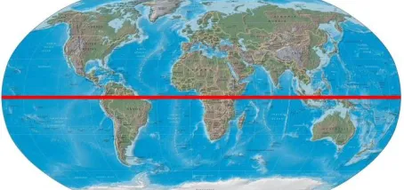
Depending on the region of the energy usage and the population density at the ground segment location as well as the available spot in orbit it is recommended to build the ground segment in Brazil or Columbia for the Americas, in Kenya or Congo in Africa depending on the political situation and Indonesia for Asia and Australia (Figure 3). Subject to the distance of the power plant to the grid, energy storage options needs to be considered.
Figure 3: World map with possible locations of SBSP ground segments
III.I Space Segment
As mentioned above, the orbital part of the SBSP station is based on a similar architecture then NIAC’s SPS-ALPHA [3]. The design consists of mainly two components, the rigid solar panel/energy transmitter and
a deployable concentrator that redirects the suns energy on the solar panel.
Solar Panel/Power Transmission Assembly
The solar panel and power transmission assembly is made up of rigid hexagons which have a diameter of just less than five meters in order to stack a few of them in the launchers available today. The hexagon shells that can be seen in Figure 4 have a high efficiency solar panel on the top and a power transmission system on the bottom pointing towards the ground segment. The energy transmitting systems will use either laser or microwaves for power transmission to the ground. Power transmission via laser or microwaves have currently the same technology readiness level (TRL) but their application depends on the legal framework and safety concerns of using those technologies for power transmission through the atmosphere.
Figure 4: Schematic of rigid solar array / power transmission system
The rigid shells are assembled in space shortly after arriving at their destination in a geostationary orbit. Each hexagon has mechanical and electrical interconnects on each of its six sides with which each panel simply locks into place with its neighbour’s. Over the interconnects, the panel shares health data with the other panels for transmission and monitoring to the ground. It is envisioned to use assembly robots to build up the panels in orbit and perform maintenance tasks of exchanging broken panels in case of damage through space debris or micrometeoroids for example.
Deployable Concentrator
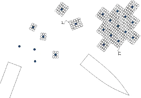
[image:2.612.74.295.209.328.2] [image:2.612.322.536.286.387.2] [image:2.612.71.298.501.608.2]Each colony is either a two dimensional plane or a three dimensional cube made up of inflatable cells surrounding a central pressure source. The modular colonies as well as the cells are scalable to be adapted to a desired application ranging from nano scale to macro scale. The high pressure source is filled at the beginning of the mission and uses the gas stored in the pressure tank to inflate individual cells and change the overall shape of the structure until the tank is empty. The global structure is made up of a number of similar self-sustaining and self-controlling cellular colonies deployed from a payload fairing, which is only a small fraction of the volume of the deployed structure.
Each of the flexible dishes of the space based solar power plant can be either free flying (or formation flying) in a predefined distance to the solar panel assembly or it could be mounted on a very light substructure like it is proposed in SPS-ALPHA [3].
[image:3.612.72.299.427.585.2]There are various options to deploy and assemble these colonies to create the full structure in orbit. One option is to deploy hundreds of these colonies in a single launch and inflate them with the desired cellular configurations. A construction robot can then assemble the global structure from the free flying colonies. The advantage of this approach is that the assembly robot can inspect the structures before assembly and use only the colonies which are fully functional. The assembly robot can also be used to simply reconfigure the structure and exchange broken components.
Figure 5: Schematic of deployment with the release of colonies from launcher and assembly via free-flying robot.
IV. BIOINSPIRED STRUCTURE
Over millions of years nature optimised it’s organisms to survive the harsh conditions on Earth. This evolution did not necessarily mean the survival of the strongest or biggest but more the survival of the best adapted. To take advantage of the millions of years of development, more and more systems in space [5] as
well as in our daily life are inspired by nature. A popular example is lotus effect paints enabling water and dirt repelling surfaces.
One approach is observing the performance of a plant or organism to a given stimulus, these phenomena are called tropisms.
IV.I Heliotropism and Phototropism
Certain flowers have the capability to follow the path of the sun over the sky during a day with their flower head or leaves. The phenomena was discovered and named Heliotropism by the Ancient Greeks but it was assumed it must be a passive effect with Aristotle’s logic of plants being passive and immobile organisms [6]. Following growth experiments in the 19th century, the observation was made that some sort of growth processes in the plants stem were involved and the phenomena was named Heliotropism in 1832 for the first time just to be renamed to Phototropism in 1892. The reason for the name change from Heliotropism meaning turned by the sun to Phototropism meaning deformation caused by light influences was the result of lab experiments on algae that showed strong dependence on the brightness and direction of light, not purely sun light.
The undertaken research was inspired by the movement of sunflower heads from East to West following the path of the sun during a day. In nature the phenomena Heliotropism and Phototropism can be treated as the same phenomena with having the sun as the only light source. This principle can be also observed by plants growing in arctic climates where the exploitation of heliotropism enables arctic poppies) to retain warmth within the plant [7].
IV.I Principle
of the cells resulting in an immediate collapse of the cells and therefore a closing of the leaf and trapment of the insect.
With this mechanism, the flower has the ability for comparably fast movement of its head without the need of growing additional cells. Due to the simplicity of the principle, the movement due to pressure change seems perfect for the application on deployable space structures.
IV.II Mechanical Analogue
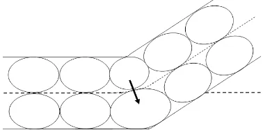
[image:4.612.327.512.220.461.2]The motor cells of plants can be taken as blueprints to develop a shape changing mechanical structure. For the mechanical analogue, a structure can be created consisting of hundreds to thousands of cells. The smallest reoccurring elements in this design are single cells which are capable of changing their volume.
Figure 6: Shape change of flat membrane induced by volume change of neighbouring cells
The shape of the overall structure can be altered by coordinated volume change of single cells in the multiple cell arrays. This volume change is undertaken by a differential pressure increase due to air molecule increase. Two methods of this pressure increase have been evaluated in previous work. One option would be the use of micro pumps in-between two cells to transfer air molecules in-between them, therefore always one cell would be inflating and the other deflating. Another option is the use of valves between all the cells with a central pressure source. The system of valves would transfer the air mass to the cell which needed to be actuated. Each method has its pros and cons and the use of one over the other needs to be evaluated for each proposed application and mission.
Cell Fabrication
An import aspect increasing the maturity and the viability of the concept is the investigation in possible fabrication techniques for the cells. Due to the wide range of application and the possible sizes, only a couple of cell types could be manufactured and tested.
The first option to manufacture the cells is to use flat circular thin Mylar sheets which are welded together on their circumference forming ellipsoids once they are inflated. An array of 5x2x1 (x,y,z direction) Mylar cells
can be seen in Figure 7. The big advantage of these materials is their availability for very thin sheets of thicknesses down to a few micro meters and there low weight but high in plane stiffness. The high in plane stiffness is advantageous for providing a semi rigid inflated cell but disadvantageous for increasing the volume farther once the cell is inflated. This is due to the high tensional stiffness of the material, keeping the cell surface area constant. The following fabrication techniques have been investigated: heat welding of the material, self-adhesive material and additional adhesive layer.
[image:4.612.83.272.280.374.2]
Figure 7: Prototype of 5x2cell deployed inflatable smart structure
overall fabrication process which allows for seamless integration all components into a single cell becomes a large design driver for the material. For this reason, a silicone based polymer material has been selected as the membrane material, which can be spun into thin sheets, cured, and then bonded at the cell borders.
IV.III Organism architecture inspired structures
The above mentioned design can be even taken a step further into the bio inspired structure by creating a system consisting of cells that have different properties creating as an analogue to a living organism. Each cell can be optimized for one specific application decreasing the overall mass of the system. Also a combination of highly specialized cells and common flexible cells is possible; the best approach depends highly on the application of the system.
Skeleton Cells
The possibility to have rigid elements in the system gives the structure a predefined shape to overcome gravity or other perturbations. The rigid elements can form a skeleton that can act as a backbone or supporting structure. The options of the deployment of these elements are either to already launch them in their rigid configuration or to inflate the cells in space and then rigidized them once deployed. When using thermal rigidisation, the possibility exists to reverse the rigidization by heating up the cell and rigidize it in a new configuration.
Muscle Cells
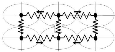
[image:5.612.335.530.390.478.2]The shape changing cells can be treated as an analogue to muscle cells in an organism. By adding arrays of these flexible or active cells in-between the interlinks of the substructure obtained by the skeleton cells the structure becomes more stable and the actuation can be better controlled due to the higher overall stiffness. An example can be seen in Figure 8 of an active joint with three types of cells, the rigid skeleton cells in red, the passive flexible cells in white and the shape changing cells in green.
Figure 8: Schematic of cellular principle: Red cells are rigid, green are actuator cells and white are flexible cells
V. SIMULATION
The undertaken simulation for the smart deployable structure focuses on the substructure for a concentrator or reflector that is deployed via inflation, taking advantage of the very low stored volume of the structure during launch. The focal point of the concentrator can then be adjusted by changing the curvature of the structure. This capability is required for space based solar power collectors, which must direct solar radiation to a single point in a geostationary orbit in order to have one stationary receiver on the Earth’s surface. Over the course of a day, the incoming light of the sun needs to be redirected by an adaptive mirror or concentrator on the surface of the solar panel collector.
All the following calculations and simulations are undertaken in the fixed geostationary reference frame of the spacecraft without any perturbations. The z-axis is oriented towards the solar panel assembly and the sun. During the mission, the concentrator changes its curvature in the z-direction in order to refocus the sun’s energy on the solar panel.
V.I Developed Code
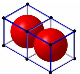
[image:5.612.74.286.563.658.2]Due to the multitude of potential applications and cell geometries, it was decided to create a parameterized simulation code which can be scaled to the appropriate application dimension.
Figure 9: Schematic of discretisation of cells
Figure 10: Two inflatable cells (red) inside discretisation cubes made out of beam elements (blue) in-between nodes (black)
Every array has (ncell x+1) × (ncell y+1) × (ncell z+1)
nodes (where ncell i is the number of cells in the
i-direction) resulting in a total of 108 nodes for a 5x5x5 cell array. The equation of motion is written with mass matrix M, damping matrix D and stiffness matrix K. Entries in all three matrices are dynamically modified based on the inflation and deformation that each cell experiences during the simulation cycle. An example of this change would be the added mass and stiffness while inflating a cell. The coupling terms in the stiffness matrix are especially important for the out of plane deformation of the entire structure.
̈ ̇
The equation of motion in above is continuously solved in the time domain to obtain the displacement
and the velocity ̇ . The input variable is the changing force within the cells and the external forces perturbing the structure. The actuation forces are the internal inflation force Finf and actuation force Fact as
well as all the external forces summarized by Fext. In the
developed model, all the forces are applied to the nodes of the cubes and algorithms have been created to distribute the forces according to their application.
V.III Inflation
Figure 11.b shows the qualitative displacement of the nodes of a 5x5x2 cell structure (Figure 11.a) with an inflation time of 4 seconds and a linear gas inflow. It can be seen in Figure 11.b that the whole inflatable structure oscillates slightly after the inflation is complete. Each of the lines in this plot shows the
displacement of each node in the structure over time. After inflation is complete, the differential pressure
stays constant but it is also possible to apply a leakage to certain cells or the entire array of cells. In practice, this leakage could be caused by micrometeoroid impacts, fabrication errors, degradation of materials, or
natural leakage of an inflatable in the space environment.
Figure 11: a) Inflated 5x5x2 cell array, b) Displacement of x-, y-, and z-positions
V.IV Actuation
The inflated dish has to be capable of changing its focal point on the surface of the target. After the deployment through inflation has formed a flat sheet, the cells are actuated to form the curved concentrator dish. During this actuation process, air mass is transferred from the top cells to the bottom cells resulting in a positive curvature of the dish. To change the focal point, the structure was actuated twice with the second actuation cycle having twice the air mass exchanged from the top to the bottom layer. Figure 12 shows the evolution of the deformation of cells from due to actuation. To increase the readability of the graphs, only the bottom layer of the full array from Figure 11 is displayed. Figure12.a shows the array before actuation, while Figure12.b shows the array after being actuated once, and Figure 12.c shows the increased curvature of the structure after being actuated twice.
Figure 12: Bottom layer plot of a) inflated structure, b) structure actuated once and c) structure actuated twice
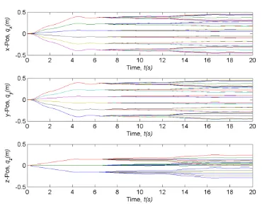
The position over time of all the nodes can be seen in Figure 13. In the first four seconds of the simulation the structure was inflated homogenously. After the oscillation was mostly settled, the first actuation was started at six seconds with a linear increase for four seconds. The second actuation, also shown in Figure 13, was started at 12 seconds and also lasted for four seconds with a linear increase.
[image:6.612.112.273.68.217.2] [image:6.612.318.526.112.184.2] [image:6.612.319.540.463.510.2]highly dependent on the chosen material and application.
Figure 13: Displacement of nodes during inflation in all directions (t<4s) and actuation (t>4s)
VI. TECHNOLGY DEMONSTRATOR Considering the economics to launch a technology demonstrator mission, various factors need to be considered including launch, development, fabrication and validation costs.
Based on the assumptions in 2013’s SGAC SSP paper [12], the average development and production costs for a communication satellite can be taken as 100,000 $/kg. Each of the hexagon solar panel / power transmission assemblies of the proposed design has a diameter of 4m and therefore an area of 10.39m2. A solar array coverage of 80% leads to a solar array area of 8.3m2 per hexagon. The area-specific mass of the hexagon arrays was assumed to be around 19kg/m2 with a thickness of 15cm [13] giving each array a mass of 197kg. For the technology demonstrator it is considered to create a circular array of 19 elements with a total assembled diameter of 16m and a solar array area of 158m2. By assuming a solar array efficiency and transmission efficiency of 12% and incident power of 1400 W/m2, the rigid hexagon array alone could produce 33.2KW. Of course this would be only the case if the array is perpendicular to the sun which is for a geostationary platform only the case for a few minutes every 24hours. By considering 19 of the rigid panels, a stacked height in the launcher of 5m is taken up including protective layers between the arrays.
Furthermore, an assembly and maintenance robot needs to be launched. For the robot a height of 1m, and a mass of 100kg and development and fabrication cost of just under 10M$ is assumed.
For the flexible array, the development costs are taken as double the amount of the hexagon assembly due to its low TRL level and low specific weight. The value was therefore set to be 200,000$/kg. For the technology demonstrator it is considered to use 5 free flying shape changing concentrators which are each
made out of six inflatable colonies. The six colonies for each concentrator are also stored in the launcher forming a hexagon outline with one colony in each triangle (Figure 14). The height of each stored concentrator is 50cm. Each colony consists of a rigid section with cold gas generator and central computing unit surrounded by the hyperelastic reflective cells with MEMS valves for actuation.
Figure 14: Six uninflated colonies forming one concentrator assembly stored in launcher payload
The mass of each colony is assumed with 100kg and an stored volume of 0.8m3 of which 0.5m3 are the flexible deployable and 0.3m3 are the rigid components. Experiments at the University of Strathclyde [14] showed that the hyperelastic cells are capable of expanding up to 900% of its original uninflated shape creating a rectangular concentrator with 5m edge length and a thickness of 20cm. Six of these single colony concentrators are assembled to one free-flying concentrator of 10m x15m giving each concentrator an area of 150m2. As there are a total of five concentrators, the total area becomes 750m2. The advantage of the smart concentrators is that they are changing their shape in a way that always redirects the maximum solar energy to the rigid solar array assembly. By assuming again an incident power of 1400 W/m2 and a transmission efficiency of 12%, the maximum power output of this technology demonstrator mission becomes 126KW.
[image:7.612.340.519.177.293.2]therefore the Proton launch vehicle was selected over the SpaceX launchers adding 100$ to the current costs. The Proton payload volume has a diameter of 4.1m and a height of the circular section of 9m for the Proton K and 15.8m for the Proton M. [18].
The total cost of the technology demonstrator mission is estimated to just over one billion dollars which results in a power cost of 8.3M$/kW which will probably increase because a ground station to collect the energy is needed as well.
VII. FURTHER APPLICATIONS
The developed smart structure and simulation method has numerous applications due to the structures scalability from atom size self-assembling and deforming nano machines up to hundreds of meter big cells to form very large space structures.
The proposed adaptive shape changing structure has various applications. One application could be as a substructure of a solar sail which would be deployed via inflation, obtaining a flat area for the solar particles to accelerate the spacecraft. Furthermore, the flat sail can then be bent to change the area subjected to the solar wind and therefore make the spacecraft steerable with just the solar sail, and no need for additional thrusters.
An application for planetary or terrestrial rovers can be envisioned as well. The smart cellular structure could be actuated to move similar to a snake over any kind of terrain, or even swim through water. Due to the fact that the actuation works with inflating and deflating the cells, the soft robot rover can actually squeeze through small openings giving it an advantage compared to conventional robots. Further applications of this soft robot can be in disaster relief, for example to search for survivors in a collapsed building after an earthquake.
.
VIII. ACKNOWLEDGEMENTS
The author would like to thank the Space Generation Advisory Council (SGAC) as well as the Space Power Committee of the International Astronautical Federation (IAF) for selecting this paper as the winner for the 2014’s International Space Solar Power (SSP) Competition for Students and Young Professionals. The competition was an initiative held in collaboration with the Space Power Committee of the IAF and sponsored by Space Canada.
IX. CONCLUSIONS
The overall system design of the space based solar power satellite described in this paper was based on a geostationary orbital platform that has one distinct ground location where the energy could be transmitted to for storage and distribution in the proper grid. The space segment consists of a rigid part made up of interconnecting hexagon shaped shells that have solar panels on top and power transmitters using either laser
or microwaves on the bottom towards the ground segment. Flexible shape changing concentrators are either free flying in formation or mounted on a substructure are used to redirect the suns energy on the solar panel assembly. The design of the flexible concentrator is biologically inspired by the capability of certain plant cells to change their shape in order to change the appearance of the whole organism. A mechanical analogue was created where a structure was made up of multiple colonies of inflatable cells fabricated of hyperelastic material. Microvalves and micropumps between the cells enable the cells to inflate and deflate in a coordinated measure to change the shape of the entire structure. A multibody code was created and undertaken simulation showed that the structure can adjust its focal point and orientation depending on the position of the sun to ensure that always the right amount of the sun’s energy is redirected towards the solar panel assembly. Especially the low storage volume und the reliable deployment of the concentrator should greatly decrease the costs of launching such a large structure into space. As an example, the system design, power budget and costs of a SBSP technology demonstrator mission that can be launched in just one launch has been presented. The technology demonstrator could be launched with a Proton rocket delivering 126KW for just over one billion dollar.
REFERENCES
1
J. Mankins, “The first International Assessment of Space Solar Power: Opportunities, Issues and Potential Pathways Forward”, International Academy of Astronautics (IAA), 2011
2
C. Mangenot, J. Santiago-Prowald, K. van't klooster, , N. Fonseca, L. Scolamiero, F. Coromina, P. Angeletti, M. Politano, C. Elia, D. Schmitt, M. Wittig, F. Heliere, M. Arcioni, M. Petrozzi, M. Such Taboada "ESA Document: Large Reflector Antenna Working Group - Final
Report," Technical Note
TEC-EEA/2010.595/CM. Vol. 1, 2010.
3
J. Mankins, N. Kaya, and M. Vasile. "Sps-alpha: The first practical solar power satellite via arbitrarily large phased array (a 2011-2012 nasa niac project)." In 10th International Energy Conversion Engineering Conference. 2012.
4
5
R. Vidoni, T. Mimmo, C. Pandolfi, S. Cesco and F. Valentinuzzi, ‘Mimicking the thigmotropic behaviour of climbing plants to design a tactile-based grasping device for the space environment’, European Space Agency, the Advanced Concepts Team, Ariadna Final Report (12-6402), 2013.
6
C. W. Whippo and R. P. Hangarter, “Phototropism: bending towards enlightenment,” The Plant Cell Online, vol. 18, no. 5, pp. 1110-1119., 2006
7
C. Galen, “Sun Stalkers: How Flowers Follow The Sun,” American Museum of Natural History, ETATS-UNIS, New York, US, vol. 108, no. 5, pp. 49-51, 1999.
8
N. Moran, G. Ehrenstein, K. Iwasa, C. Mischke, C. Bare and R. L. Satter, “Potassium Channels in Motor Cells of Samanea saman A Patch-Clamp Study,” Plant physiology, vol. 88, no. 3, pp. 643-648, 1988.
9
A. D. o. Biology, Encyclopedia.com, 2004. [Online]. Available: http://www.encyclopedia.com. [Accessed 13 04 2014].
10
T. Sinn, T. Bogicevic, M. Vasile ‘Self-folding Smart Structure inspired by Nature’s Heliotropism‘, European Conference on Spacecraft Structures, Materials and Environmental Testing (SSMET2014), Braunschweig, Germany, 1-4 April 2014.
11
T. Sinn, M. Vasile ‘Multibody Dynamics for Biologically Inspired Smart Space Structure‘,
AIAA-2014-1364, AIAA Science and
Technology Forum and Exposition
(SciTech2014), National Harbour, Maryland, USA, 13-17 January 2014.
12
M. Leitgab ‘Hypermodular Distributed Solar Power Satellites – Technology Option for Near-Term LEO Demonstration and GLPO Full-Scale Plants’, 64th International Astronautical Congress, IAC 2013, Beijing, China, 23-27 September 2013.
13
P. Jaffe and J. McSpadden, ‘Energy Conversion and Transmission Modules for Space Solar Power’ Proceedings of the IEEE 101, 1424 (2013)
14
E. Perez. "Ariane 5 User’s Manual Issue 5 Revision 0." Ariane 5 User's Manual (2008).
15
T. Sinn, T. Bogicevic and M. Vasile(2014) ‘Self-folding smart structure inspired by nature's heliotropism’ European Conference on Spacecraft Structures, Materials and Environmental Testing, SSMET 2014, 1-4 April 2014, Braunschweig, Germany.
16
‘Falcon 9 Launch Vehicle Payload User’s Guide, Rev 1’ SpaceX.
17
‘Falcon Heavy Overview’. SpaceX. 2013
18
![Figure 1: Artist Impression of SPS-ALPHA [3]](https://thumb-us.123doks.com/thumbv2/123dok_us/1649406.118472/1.612.322.534.532.705/figure-artist-impression-of-sps-alpha.webp)