City, University of London Institutional Repository
Citation:
Slabaugh, G. G., Mihalef, V. and Unal, G. B. (2005). A Contour-Based Approach
to 3D Text Labeling on Triangulated Surfaces. In: Fifth International Conference on 3-D
Digital Imaging and Modeling, 2005 (3DIM 2005). (pp. 416-423). IEEE Computer Society.
ISBN 0-7695-2327-7
This is the accepted version of the paper.
This version of the publication may differ from the final published
version.
Permanent repository link:
http://openaccess.city.ac.uk/4405/
Link to published version:
http://dx.doi.org/10.1109/3DIM.2005.7
Copyright and reuse: City Research Online aims to make research
outputs of City, University of London available to a wider audience.
Copyright and Moral Rights remain with the author(s) and/or copyright
holders. URLs from City Research Online may be freely distributed and
linked to.
A Contour-Based Approach to 3D Text Labeling on Triangulated Surfaces
Greg Slabaugh
Intelligent Vision and Reasoning Department
Siemens Corporate Research
Princeton, NJ USA
greg.slabaugh@siemens.com
Viorel Mihalef
Center for Computational Biomedicine Imaging and Modeling
Division of Computer and Information Sciences
Rutgers University
New Brunswick, NJ USA
mihalef@paul.rutgers.edu
Gozde Unal
Intelligent Vision and Reasoning Department
Siemens Corporate Research
Princeton, NJ USA
gozde.unal@siemens.com
Abstract
This paper presents a simple and efficient method of forming a 3D text label on a 3D triangulated surface. The label is formed by projecting the 2D contours that define the text silhouette onto the triangulated surface, forming 3D contour paths. Surface polygons upon which the 3D contour paths lie are retriangulated using a novel approach that forms a polyline defining the region outside the contour. This algorithm produces labeled 3D surfaces that conform to the specifications of the STL format, making them suit-able for fabrication by a rapid prototyping machine. We demonstrate the effectiveness of the algorithm in forming flat and extruded labels on non-trivial surfaces.
1
Introduction
Object labeling is essential for many tasks, such as in-ventory control, object identification, and tracking. For ex-ample, in manufacturing, assembly of a product composed of many parts is considerably simpler when each individual component is labeled so that it can be identified. Likewise, given an object, one might like to know about its history or attributes. If the object is labeled, one can input the label
into a database to retrieve such information.
In this paper, we present a digital, geometric approach to form a 3D label on a 3D triangulated surface. An appli-cation or user supplies the computer with a set of charac-ters and a position on the surface for placement of the label. The technique then back-projects the 2D contours of the text onto the surface, merges the text to the surface, and extrudes the text into a 3D label, in a way that produces a 3D model that can be fabricated by a rapid prototyping machine.
Several steps of this process, such as back-projection and 3D extrusion are quite straightforward. However, the most challenging aspect of this 3D labeling task is integrating the text geometry with that of the surface. In our application, this geometric integration must achieve the following goals:
1. It should not distort the geometry of the surface for points located outside of the projection of the label.
2. It should be fast; i.e., labeling an object should take at most a few seconds.
We achieve the above goals by introducing an algorithm that quickly integrates each text character of the label with the surface, by retriangulating the triangles upon which the character projects so that the region outside the character consists of triangles, and the region inside the character is empty space, as depicted in (a) and (b) of Figure 1. This algorithm is the primary contribution of this paper. Once integrated, the character geometry can be extruded into 3D so that the text label is indented, flat, or protruding rela-tive to the surface. This process can be repeated for more characters, forming a longer text string. The labeled surface can then be output as an STL file for fabrication on a rapid prototyping machine.
2
Relation to previous work
We are unaware of any papers specifically focused on the problem of 3D text labeling as described above. However, there is much literature devoted to merging and cutting 3D surfaces in the computer graphics and computer aided de-sign (CAD) literature. We discuss the most related work below.
Constructive solid geometry (CSG) [3, 6, 8] is a pow-erful way to model 3D surfaces by the application of reg-ularized Boolean set operations. For example, using such techniques, a complex polyhedral object can be formed as the union, intersection, and/or difference of simpler polyhe-dral objects. The method presented in [6] applies CSG to two polyhedral surfaces. First, all polygons in each of the two surfaces are subdivided so that no two polygons inter-sect. Then, the polygons of each object are classified with respect to the surface of the other object. This classifica-tion is achieved by casting rays from the polygon through the other object and checking the surface normal. Based on this classification and the set operation, the technique will retain or delete the polygon. Alternatively, the method presented in [8] implements polyhedral set operations using BSP trees.
These general-purpose CSG techniques require numer-ous tests to determine which polygons intersect and to clas-sify polygons of surface A as being in, out, or on the bound-ary of surface B. In contrast, the method presented in this paper reduces the complexity of the problem by first pro-jecting the points defining the text characters onto the 3D surface. Doing so obviates the need for complicated in-tersection tests, and reduces the 3D/3D surface inin-tersection problem to a simpler contour-based problem on the 3D sur-face. Furthermore, such CSG methods will not, in general, produce a triangle-based surface that satisfies the vertex-to-vertex rule. Therefore, if such methods are used, post-processing of the surface is necessary to generate a valid STL file for rapid prototyping applications.
Since our text labeling approach extrudes letter contours
from a 3D surface, it bears some relation to offset curve methods [7, 9] that appear in the CAD literature. The specific nature of text labeling ensures that the extrusion distance is kept small enough so that local or global self-intersection does not become an issue. In addition to pro-ducing offset curves during extrusion, we integrate the ex-truded text with the surface to produce the label.
One could regard the core of our 3D labeling method as a mesh-cutting technique; following [1], our method is characterized by placing a template through the mesh and remeshing the intersected primitives (triangles, in our case). The methods falling in the same category with ours cited in [1] do not report on the implementation of their local remeshing techniques so it is unclear to what extent their remeshing is STL compliant and geometry-preserving. With minimal modifications, our remeshing al-gorithm could be successfully applied to interactive surface surgery that preserves the STL attribute of the initial mesh. Given a set of 3D text character points, along with the surface triangle vertices, it would be possible to delete all surface triangles upon which the 3D text points project, and then retriangulate the region of space between the remain-ing surface triangles and the 3D text points usremain-ing a meshremain-ing algorithm like constrained Delaunay triangulation [10] or advancing front triangulation [4]. However, unless special care is taken, direct application of these methods will al-ter the surface geometry for regions outside the text, since these methods might form new triangles using vertices that lie on different triangles of the original surface. Where the surface is non-planar, the new surface geometry will dif-fer from the original surface geometry. When retriangulat-ing, in our method we only break apart existing triangles on the surface and therefore do not alter its geometry outside the text label. We implement our retriangulation by pass-ing contours to OpenGL and therefore do not require any complicated data structures.
Finally, we note that labeling of tracked objects in video [5] has appeared in the literature. However, unlike these methods that superimpose a label on top of the video, our technique modifies the scene geometry to include the label.
3
Description of the approach
In this section we describe the details of our 3D text la-beling algorithm.
3.1
Extracting 2D contours and placement on
sur-face
(a) (b) (c)
Figure 1. Letter integration and extrusion. In (a), the two gray triangles indicate a portion of a larger 3D surface. The darker gray polyline is the back-projection of a capital L letter onto the surface. The labeling problem seeks to retriangulate the triangles upon which the character projects so that the region outside the character consists of triangles, and the region inside the character is empty space, as shown in (b). Next, the character can be extruded from the surface and closed, as shown in (c).
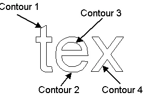
the software. We then extract the 2D contours of the letters in the text string. Most operating systems provide functions that allow one to obtain these contours. In particular, we use the GDI path functions [2] that are part of Microsoft Win-dows. These functions convert the text shape composed of B´ezier curves and straight lines to collection of closed poly-line contours as shown in Figure 2. Each contour is stored in a linked list. The points in the polylines are oriented so that the region outside the letter is always located to the right of the contour, as depicted in Figure 3.
Figure 2. 2D contours defining letter shape.
Next, the location on the surface where the text label should be placed is specified. This can be done automat-ically; however, in our application the user drags the text la-bel so that it hovers over the region of the surface to where the label should project. We demonstrate the positioning of the label in Figure 4.
[image:4.612.94.240.467.567.2]Next, the approach back-projects the 2D vertices that de-fine the text onto the 3D surface. These points are shown in
Figure 3. Orientation of 2D contours.
gray in Figure 5, for the capital L example. Figure 5 also shows the vertices of the surface triangles in black. In order to perform the retriangulation, we will also need the points at which the projected contour intersects the edges of the surface triangles. These intersection points are shown in white in Figure 5. We compute them by intersecting the surface triangle edges with a plane formed from pointsVi, Vi+1, and C, whereVi andVi+1 are two successive 3D
letter contour points, andCis the camera’s center of pro-jection from which the back-propro-jection occurs. In the ex-ample shown in Figure 5 (b), our approach computes the pointA, in betweenVi andVi+1. We insert point Ain
our list of contour points so that it appears betweenViand Vi+1. We repeat this procedure to find the other
intersec-tion points in the figure. At the end of this step, we have a new ordered list of 3D letter contour points that includes both the back-projected contour points (shown in gray) and the intersection points (shown in white). If the projections ofViandVi+1 fall inside triangles situated far from each
(a) (b)
Figure 4. Positioning of the 2D text label. The user clicks the black square to drag the label into position. We show both shaded (a) and wire-frame (b) renderings.
C Vi Vi+1. We use the local connectivity information to
find these triangles efficiently.
3.2
Merging the label and the surface
To avoid altering the surface geometry, we perform the remeshing only within existing surface triangles. This has the additional benefit of reducing the 3D remeshing prob-lem into a 2D remeshing probprob-lem. Each 2D region is remeshed using OpenGL’s (GLU, Version 1.2) tessellation functions. These functions create a series of triangles that satisfy the vertex-to-vertex rule given a closed polyline, and support triangulation of complex polygons. Thus, our task is to now identify, using only points on a triangle, a closed polyline that covers the region of space to be triangulated.
Figure 6 illustrates this process. The method starts with an entry point, which is an intersection point at which the text character contour enters a triangle. For example, such a point is vertex 1. The approach then follows the letter contour while it is on triangle T1, adding vertices 2 and 3
to polyline. At vertex 3, the letter contour exits T1. Since
we want to only remesh using points that are on T1, we add
vertex 4 to the polyline. We find vertex 4 by identifying the closest vertex that is on the triangle edge64that contains vertex 3, and positioned on the right (i.e., clockwise) of the letter contour. We always look in a clockwise direction, since the region of space to the right of the letter contour is the region to be filled in. Once at vertex 4, we look along the triangle edge45to see if the edge intersects the letter contour. If not, we add vertex 5 to the polyline and move to edge56. Again, we look to see if the edge intersects the letter contour. Again, it does not, so we add vertex 6 to the polyline and advance to edge64. Edge 64does intersect the contour, and we find the closest point of intersection to vertex 6. In this case, it is vertex 1, the starting vertex in the polyline. We now have a closed polyline representing a region of space to be triangulated. We give this polyline
to OpenGL, which triangulates the region, as shown in Fig-ure 6 (b).
At this stage, we have processed one region of triangle T1. We repeat the process for other regions of the triangle,
until all regions outside the text contour have been retrian-gulated. Next, we repeat this process for all triangles to which the text contour projects, until the entire text contour geometry has been integrated.
While we described the algorithm in the paragraphs above and illustrated it in Figure 6 for a specific example, the principles apply to any letter and any surface triangle. Pseudo-code for the general algorithm for processing a let-ter contour is shown in Code Listing 1. For the general algorithm, we must additionally consider the special cases where all the points of a contour lie within a triangle, for which no intersection points exist. However, these cases are simple to detect and handle. One case is when all ver-tices of the letter project to one triangle. In this case we pass a polyline consisting of the 3 vertices of the triangle to OpenGL, followed by all contours corresponding to the let-ter. OpenGL will then tessellate the proper region of space inside the triangle. Another case exists when the contours of the letter project to different triangles, but each contour lies within its own triangle. For example, such a case can occur when the dot of a lower case “i” projects to one trian-gle, but the base projects to another. In this case, for each triangle we again send polyline consisting of the 3 vertices of the triangle to OpenGL, followed by the text contour in the triangle.
(a) (b)
Figure 5. 3D points used in the integration. The black vertices at the 4 corners of the image represent the 3D vertices of the surface triangles. Each 2D point of the letter contour is projected onto the surface, yielding the gray points. Our approach computes the intersection points (shown in white), which are located at the intersection of the triangle edge with a plane connecting pointsC,Vi, and Vi+1, as shown in (b). See text for details.
[image:6.612.142.445.332.468.2](a) (b)
Figure 6. Remeshing. We find a polyline on triangle T1(a) and tessellate it (b) using OpenGL.
form the walls and the top of the extruded label. All of these newly formed triangles are added to the surface. This then completes the formation of the 3D text label for the letter.
It is worthwhile to consider under what circumstances this method may fail to produce a valid labeling of a surface. Clearly, if the 2D text contours do not all project onto the surface then an erroneous result may occur. However, this case is easily detected, and can be handled by moving the camera. Additional problems could occur for a surface that is extremely noisy. While the integration of the text works properly, extrusion based on the surface normal may cause the extruded geometry to self-intersect. As before, this case could be easily detected, and handled by prevention of self-intersecting extrusions. However, in practice such this issue has not appeared in our experiments.
4
Examples
We now present examples to demonstrate the labeling algorithm. In Figure 7 (a) we show a CAD part that we would like to label with the part number “A43”. We type the characters “A43” in our program and position the label. We then project the characters on the surface, merge the text geometry with the surface, and extrude the text towards the camera to produce protruding label. Flat shaded and wireframe renderings of the labeled part are shown in (b) and (c) of the figure.
function ProcessLetter()
extract 2D letter contours c1· · ·cN
back-project c1· · ·cN to the 3D surface, forming surface contours C1· · ·CN flag = false
if (all points C1· · ·CN lie in triangle T)
pass contour formed from T’s three vertices to OpenGL, set flag = true for each surface contour Ci∈C1· · ·CN {
if (Ci is the only contour in triangle T && flag == false && Ci is oriented counter-clockwise) pass contour formed from T’s three vertices to OpenGL
processContour(Ci)
}
tessellate using OpenGL
delete all original surface triangles to which the letter projects
function ProcessContour(Ci)
find contour intersection points (white points in Figure 3a) if (number of intersection points == 0) {
send Ci to OpenGL for tessellation return
} else {
insert contour intersection points into Ci
select starting point S on a triangle T so that S is an entry point into T, set P = S add P to L, the polyline that will be passed to OpenGL
P = P + 1, the next point on the text contour Ci while (true) {
if (P is a point on a triangle edge) {
add P to L
P = closest point on edge of T where point P is located, in a clockwise direction while (P is a triangle vertex) {
add P to L
P = closest point on edge of T where point P is located, in a clockwise direction
}
if (P == S) {
send L to OpenGL for tessellation, clear L if (all points in Ci processed)
return
P = next unprocessed entry point, S = P T = triangle being entered
} }
add P to L P = P + 1
} }
Code Listing 1. Detailed pseudocode for processing a letter. An example is described in Section 3.2.
[image:7.612.103.491.526.618.2](a) (b) (c)
Figure 7. A protruding label on a 3D CAD part. Before labeling, the surface is composed of 8,260 triangles. After labeling, it is composed of 8,775 triangles.
and wireframe renderings.
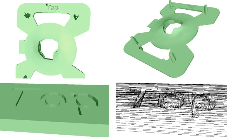
Figures 10 and 11 demonstrate the labeling of surfaces
Figure 8. An indented label on a 3D CAD part. The surface is composed of 27,800 and 28,799 triangles before and after labeling, respectively.
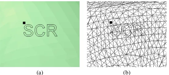
side of the surface, for which label is indented, and in (c) and (d) we show the back side of the surface, where the label protrudes. Finally, in Figure 9 we generate a flat label on the surface, but render the text triangles in a different color.
Figure 9. Forming a flat text label on a surface.
For all of these examples, the label was integrated into the surface in less than 5 seconds using a 2.66 GHz Pentium 4 processor and unoptimized C++ code. In addition, using VisCAM RP 2.01 [11], we have verified that our labeling satisfies the requirements of the STL format.
5
Conclusion
In this paper we presented a geometric approach to form a 3D label on a 3D triangulated surface. The method in-tegrates the geometry of the projected text with that of the surface, in a way that does not change the surface geometry outside the label. The algorithm is simple, efficient, robust in regions of high-curvature, and produces a 3D model that can be fabricated by a rapid prototyping machine.
For future work, we are interested in further automation of the method so that it automatically positions the label on the surface. In addition, we plan on adapting the remeshing algorithm to perform interactive mesh surgery.
6
Acknowledgements
We thank Jason Tyan and Tong Fang of Siemens Cor-porate Research for discussions and assistance with this project.
References
[image:8.612.114.227.459.594.2](a) (b) (c)
Figure 10. A protruding label on a surface with curvature. The surface is composed of 10,503 and 11,967 triangles before and after labeling, respectively.
(a) (b)
(c) (d)
Figure 11. An indented label on a surface with curvature.
[2] Chandler, D., and Fotsch, M., Windows 2000 Graphics API Black Book, Coriolis Technology Press, 2001.
[3] Foley, J., Van Dam, A., Feiner, S., Hughes, J., Computer Graphics, Principles and Practice, 2nd Edition, Addison-Wesely, 1996.
[4] George, P., Automatic Mesh Generation: Applications to Fi-nite Element Method, John Wiley and Sons, 1991.
[5] Geys, I., Van Gool, L., “Virtual Post-its: Visual Label Extrac-tion, Attachment, and Tracking for Teleconferencing,” Proc. of 3rd International Conference on Computer Vision Systems (ICVS), pp. 121–130, 2003.
[6] Laidlaw, D., Trumbore, W., Hughes, J., “Constructive Solid Geometry for Polyhedral Objects,” Proc. Siggraph 1986, pp.
161 – 170.
[7] Maekawa, T., “An Overview of Offset Curves and Surfaces,” Computer-Aided Design, Vol. 31, 1999, pp. 165 – 173. [8] Naylor, B., Amanatides, J., Thibault, W., “Merging BSP Trees
Yields Polyhedral Set Operations,” Proc. Siggraph 1990, pp. 115 – 124.
[9] Pham, B., “Offset Curves and Surfaces: A Brief Survey,” Computer Aided Design, 1992: 24(4), pp. 223–229.
[image:9.612.108.490.262.535.2]