IAC-12-E2.3.7
STRATHSAT-R: DEPLOYING INFLATABLE CUBESAT STRUCTURES IN MICRO GRAVITY
Ruaridh Clark
Mechanical & Aerospace Department, University of Strathclyde, United Kingdom, [email protected]
Thomas Sinn*, Charlotte Lücking†, Nathan Donaldson‡, Roy Brown§, Thomas Parry**, Iain Dolan††, Christopher Lowe ‡‡, Russell Bewick §§
This paper presents the concepts, objectives and design of a student-led sounding rocket experiment which shall test novel inflatable devices in space conditions. This experiment is envisaged as the first step towards developing a CubeSat programme at the University of Strathclyde, which can exploit the novel concepts developed and the technical skills gained. The experiment itself aims to test novel, student developed, inflatable space structures in micro gravity and reduced pressure conditions. It consists of three distinct sections, the ejection housing on the rocket and the two ejectable modules that are based on CubeSat architecture. Shortly before reaching apogee, the two modules are ejected from the rocket and will deploy their own inflating structure during free flight. After landing, the ejectable modules recovery will rely upon a GPS position relayed to the team from the module by Globalstar transmission and a RF beacon for tracking with the recovery helicopter. The two modules carry two different structures resulting in distinct mission objectives: The aim of FRODO is to deploy an experimental passive de-orbiting system for high altitude spacecraft which will in the future utilise solar radiation pressure for orbit removal. The aim of SAM is to serve as a technology demonstrator for the residual air deployment method of a smart bio-inspired space structure. This paper contains details about the science objectives of the mission and how they will be achieved, its experimental design and the management of the student-led project.
I. ACRONYMS
ASCL Advanced Space Concepts Laboratory
DLR Deutsches Zentrum für Luft- und
Raumfahrt*†‡§**††‡‡§§
EEE Electrical & Electronic Engineering Department
EMC Electromagnetic Compatibility
ESA European Space Agency
FIFO First in First Out
FPGA Field Programmable Gate Array
IMU Inertial Measurement Unit
FRODO Foldable Reflective system for
Omnialtitude De-Orbiting
*
ASCL, University of Strathclyde, Glasgow, United Kingdom, [email protected]
† ASCL, University of Strathclyde, Glasgow,
United Kingdom, [email protected]
‡
MAE, University of Strathclyde, Glasgow, United Kingdom, [email protected]
§ EEE, University of Strathclyde, Glasgow,
United Kingdom, [email protected]
**
EEE, University of Strathclyde, Glasgow, United Kingdom, [email protected]
†† EEE, University of Strathclyde, Glasgow
United Kingdom, [email protected]
‡‡
ASCL, University of Strathclyde, Glasgow, United Kingdom, [email protected]
§§ASCL, University of Strathclyde, Glasgow,
United Kingdom, [email protected]
GPS Global Positioning System
LO Lift Off
MAE Mechanical & Aerospace Engineering Department
MEO Medium Earth Orbit
MCU Microcontroller Unit
PCB Printed Circuit Board
PET Polyethylene Terephthalate REXUS Rocket Experiments for University
Students
RF Radio Frequency
RXSM REXUS Rocket Service Module
SAM Self-inflating Adaptive Membrane
SED Student Experiment Document
SEDS Students for the Exploration and Development of Space
SHIRE Storage Housing In Rocket for Ejection
SODS Start of Data Storage
SOE Start of Experiment
SNSB Swedish National Space Board
SPI Serial Peripheral Interface StrathSEDS Subdivision of UK SEDS at the
II. INTRODUCTION
In spring 2013, the StrathSat-R experiment will be launched onboard the REXUS13 sounding rocket from Esrange into space. The REXUS (Rocket Experiments for University Students) programme is organised and sponsored by the German Aerospace Center (DLR), Swedish National Space Board (SNSB) and the European Space Agency (ESA). The aim of the project is to use a sounding rocket as a test bed for novel, student developed concepts which utilise inflatable structures.
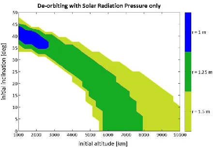
[image:2.612.77.297.416.569.2]The first concept is a solar radiation pressure (SRP) augmented de-orbiting system rooted in the research undertaken by the University of Strathclyde’s Advanced Space Concepts Laboratory. The ERC funded project is investigating highly non-Keplerian orbital dynamics and applications. The SRP-augmented de-orbiting concept is using solar radiation pressure and the J2 perturbation to passively increase the eccentricity of an initially circular orbit until the perigee is affected by drag and the spacecraft de-orbits. This technique is particularly effective in MEO but can be applied to even higher altitudes. After the deployment of the reflective sail the de-orbiting manoeuvre takes place completely passively. This research could open up new high altitude orbital regimes for future pico- and nano-satellite missions. A conical (or pyramidal) structure is needed to exploit the shuttlecock-effect which passively maintains the spacecraft in a sun-pointing position.
Figure 1: Regions in which a 1U CubeSat (1.3 kg) can be deorbited using solar radiation pressure only from an initially circular orbit using a reflective cone of given maximum cross-sectional radius (r)
The results of this research for orbits in the lower MEO regime1 are shown in Figure 1. It can be seen that a 1U CubeSat with a deployable reflective cone of around 1.2m radius can deorbit from high altitude circular orbits with a range of different semi-major axes and inclinations. The aim of this REXUS experiment is to show that such a device can be manufactured for low
costs and by students. This will hopefully pave the way for a follow up satellite mission to demonstrate the principle in orbit.
The second concept is an inflatable membrane with the capability to change its shape in orbit. This concept is driven by the constraints that are placed on space vehicle size due to launch vehicles dimensions. These constraints made the use of deployable structures necessary with their low stowage and high in-orbit volume. For the success of future space missions involving large space structures, the development of new deployable structures and the improvement of current designs are of great importance. Applications can be easily envisioned through truss structures, masts, crew quarters, transport tunnels, large solar arrays, solar concentrators, solar sails, balloons or antennas.2 Various research has been undertaken in the development of ultra-lightweight deployable structures and it cristallised out that the use of inflatable structures is a very promising approach for the middle to long-term development of space structures.3 Over the last 50 years, research has been conducted at various institutions all over the world in the field of inflatable structures; new membrane materials have been discovered that can withstand the space environment, advanced simulation tools were developed that capture the highly non-linear behaviour of the inflation process and rigidisation techniques have been investigated making the structure non-reliant on the inflation gas after deployment.4
The big advantage of the cellular element approach, used in this concept, is that a structure can be obtained which is simultaneously stiff and flexible due to the stiff pillow elements and the flexible seam lines. The second goal of this endeavour is to develop a structure that can adapt itself to various environmental conditions. For example, the structure could serve as a substructure for a solar concentrator and adjust its focal point autonomously by changing the curvature of the entire surface. By achieving an adaptable structure the number of possible applications becomes almost limitless.5 The high deployment reliability and the comparably low manufacturing costs of the inflatable structure providing a promising field of study in a university environment.
III. MISSION OUTLINE
modules will be ejected from the rocket after it has been de-spun and near to apogee, above 80km altitude. After which the structures shall inflate passively, using residual air inflation. The inflation is filmed initially by both the cameras on-board the rocket and those on the modules. During the whole flight images and measurements from sensors on the structure will be taken and stored on SD cards in the ejectable modules. Once the modules reach an altitude of around 5 km a barometric switch shall provide the release signal for the parachutes on both modules. This signal shall also activate the tracking system with GPS positions relayed through the Globalstar network and a RF beacon which will be tracked by the recovery helicopter. At this stage data should be recovered from SD cards on all three sections of the experiment, which shall be post-processed to recover the images and information.
Mission Objectives
Ejectable Module 1: Foldable Reflective system for Omnialtitude De-Orbiting (FRODO)
1) Test deployment of the device in micro gravity and near-vacuum conditions. (primary objective)
2) Test the passive attitude control. (secondary objective)
3) Observe the structural integrity of the device during the re-entry when ambient pressure rises. (secondary objective)
Ejectable Module 2: Self-inflating Adaptive Membrane (SAM):
4) Observe deployment behaviour of the full size membrane from the module in a space environment (primary objective)
5) Alter shape of the membrane autonomously without the influence of perturbing gravitational forces. (secondary objective)
IV. DESIGN IV.I Mechanical
The mechanical design of StrathSat-R is based around the three main subsystems; the SHIRE, SAM and FRODO that can be seen in Figure 2. The SHIRE provides the structural support and necessary elements for retention during launch and jettison of SAM & FRODO in space. The structure is largely machined from Aluminium 6082-T6, with electronic components, PCBs, steel machine elements, Perspex covers and Polyimide camera windows forming the rest of the assembly.
The loads experienced during launch are transferred to the Experiment Module skin via the D-Brackets and Hatch Reinforcement Blocks. Upon ejection of SAM and FRODO, the experiment is exposed to the environment. Therefore Perspex snow covers are
incorporated to prevent excessive ingress of debris during the landing phase.
The ejectable modules are segmented into three regions; one housing the subsystem electronics, one housing the deployable experiments and a third housing a parachute required for safe descent and landing. A loosely fitting lid panel is incorporated in order to enclose the deployable payload during launch, but is free to jettison upon ejection of the modules. It is held in place during launch by the compressive action between the hatch assembly and the spring platform.
Figure 2: Isometric view of experiment after ejection (hatches not displayed)
Mounting of the electronics within the ejectable modules is achieved by strapping two SAFT batteries securely against the plate that separates the payloads from the electronics enclosure. The PCBs fill the remainder of the space in the electronics enclosure, where they are evenly spaced using anti-vibration spacers.
IV.II FRODO
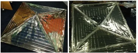
[image:3.612.319.536.216.390.2]FRODO’s payload consists of a self-inflating pyramidal structure that deploys from the module using residual air inflation in partial vacuum conditions once the module is ejected from the rocket (Figure 3).
[image:3.612.315.536.592.677.2]Residual air inflation occurs when small pockets of air are allowed to grow in volume due to the lack of external pressure.
The inflatable structure is a square-based pyramidal sail of base length 1.772 m and height 0.512 m, see Figure 3. A pyramid of this side length has a reflective surface area of 3.628 m2, which is equivalent in performance to a cone of radius 1m, shown in blue in Figure 1. This is the smallest structure which can de-orbit a 1.3 kg CubeSat effectively at altitudes just below 3000 km.
[image:4.612.322.536.344.483.2]The pyramid is comprised of eight separate and independent booms along the edges of the structure, and a reflective sail on the triangular faces of the pyramid. The square-based pyramid introduces redundancy in the base booms, where one can be deflated and the structure maintains its general shape. A partial or total deflation by a leak of one of the oblique booms may introduce deformations in the shape of the structure, but it is still an improvement from having all the booms interconnected, which could result in total failure if a leak occurred.
Figure 4: Packaged FRODO Payload
FRODO is a passively deployed structure, with no actuators in its design. The structure is deployed and its shape maintained by the inflated booms. The structure can therefore be packed very efficently, Figure 4 shows the packed FRODO payload in the CubeSat prototype.
IV.III SAM
SAM6 will inherit forty percent of the cube satellite’s structure which should lead to a membrane diameter of 72.5cm once deployed with a packing efficiency of thirty percent.
Figure 5: Schematic of SAM deployed from module
The diameter of the spherical elements is chosen to be 14.5 cm to fit the storage box of 10 cm by 10 cm in the central sphere. Figure 5 shows a cut through schematic of the SAM cube satellite with the deployable, the PCB boards and the cameras.
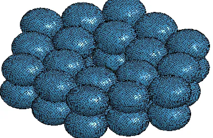
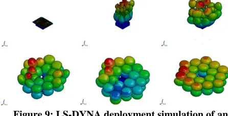
The experiment has two main stages, the deployment phase and the adaptive phase. After ejection out of the rocket is achieved, deployment gets initiated by reducing the pressure in the inflatable storage compartment. The pressure will get decreased to ambient pressure at roughly 80 km altitude. The deployable structure of SAM consists of two layers of spherical cells that are deployed by using the expansion of trapped air in the spheres when subjected to vacuum (space) conditions. The two layers of spheres are manufactured out of 12micron thick, reflectively aluminized, Polyethylene Terephthalate (PET). Each cell is manufactured by heat welding circular sheets of aluminized PET together. Figure 6 shows a LS-DYNA simulation of the inflated 36 spheres of SAM.
Figure 6: SAM with deployed structure (module to be placed in centre)
During the deployment and adaptive phase, images from three cameras on the structure will be taken and stored on board the ejectable module. The ejected cube satellites will be recovered after re-entry.
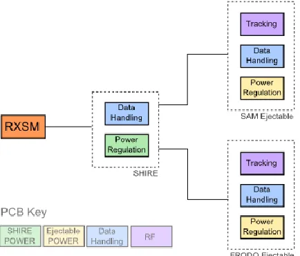
IV.IV Electronic
The system architecture is based around three core modules which are replicated for section in the experiment. The modules within the system are broken into; power, data handling and tracking. Each subsystem is located on its own PCB keeping in step with the modular design process as well as providing EMC isolation, a necessity when using high speed digital logic and RF circuitry within the same design.
[image:4.612.73.294.359.460.2] [image:4.612.72.299.621.691.2]module. The SHIRE module’s power board consists of power filtering to meet EMC conductivity requirements and high quality switching regulators regulate the sounding rocket’s supply to appropriate power rails. The tracking PCB is identical in both the ejectable units and consists of local power conditioning, GPS, Globalstar and RF beacon circuitry. Tracking is not needed in the main unit, SHIRE, as that will remain part of the recovered rocket. The data handling PCB contains a microcontroller, FPGA and I/O support circuitry. The data handling PCB is adaptable to the variety of sensors used in each module and has been designed to accommodate all the sensors needed. During manufacture only those components needed for each module will be populated which lowers PCB design and manufacture cost.
IV.V Embedded Software
The software will be developed using the MBed NXP LPC 1768 Microcontroller Unit (MCU). It utilises an ARM Cortex M3 and is a robust and flexible development unit for use in each module.
The entire development board shall be included on the surface of the flight computer PCB. This approach was chosen to allow a modular approach to be taken to developing embedded software for subsystems, to allow flexibility, and lower design complexity.
[image:5.612.79.296.478.663.2]There are not enough inputs and outputs provided on the development platform to support the intended applications alone, therefore an 8-channel I2C multiplexer, and a 16-bit SPI multiplexer has been used. The I2C multiplexer allows a single I2C interface to communicate with 8 different I2C devices. The SPI multiplexer serves to increase the number of digital I/O pins.
Figure 7: Electronic System Architecture
IV. VI Data Handling
Common to each modules’ operation is a requirement to store multiple camera feeds onto SD cards. An FPGA will be used to perform data handling from the cameras and other sensors. Due to the relatively high throughput needed for multiple cameras, the use of a microcontroller, such as the MBed, for data storage is impractical. The implementation using an FPGA allows the use of hardware optimization and parallel architectures to achieve the sufficient processing power.
The camera module provides 16 bit RGB-565 data for each pixel with a time domain multiplexed (TDM) 8 bit output. The image is raster scanned and with vertical and horizontal synchronisation flags. All control of the camera module is delivered through the I2C interface by the microcontroller. The microcontroller will also supply a data acquisition signal to the FPGA to indicate when to start and stop data acquisition and storage. Further communication between the microcontroller and FPGA will be used for the health monitoring systems, i.e. to indicate the correct programming of the FPGA at start up.
The FPGA provides the means to store all information from the sensors into parallel SD cards providing redundancy. The data from each sensor is stored in the memory whilst awaiting storage. The data from each sensor is multiplexed into blocks of data suitable for storage on the SD card. In this way the data from each sensor will be saved to the SD card in a round-robin schedule, i.e. camera one, camera two, IMU, pressure sensor, camera one, camera two etc. The multiplexed data is stored in a FIFO (First In First Out) register to avoid overflows when transferring data to the SD card. The native four data line SD bus is used to provide a data rate of up to 50Mbps. Data stored on the SD card has a header indicating the current data allowing correct data recovery even if some data is corrupted.
IV.VII Experiment Timeline
Once the experiments are ejected, at T+140s, they will use their own internal timelines, with SAM aiming to perform 5 shape changing manoeuvres before switching the cameras off while FRODO’s cameras are left on till after the parachute’s deployment.
At T+250s the microcontroller begins to sample the barometric switch, with the switch activating the tracking and recovery stage of the mission once the modules reach an altitude of 5 km above ground.
IV. VIII Tracking & Recovery
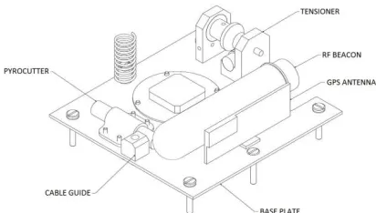
[image:6.612.78.284.436.553.2]The tracking and recovery stage of the mission is triggered by the barometric switch, which activates a pyrocutter. This severs a tensile retention wire, releasing the parachute enclosure lid. A spring and spring loaded RF beacon will then assist in removing the lid, allowing the parachute, which is fastened to the four corner screws, to unfurl. The RF beacon, as mentioned, is spring loaded and attached to hinges which allow it to be stored in a horizontal position, as seen in Figure 8, and then rotated into a vertical position in order to achieve an optimal gain pattern. After the parachute is deployed, the GPS receiver and Globalstar transmitter activate and continue to relay GPS coordinates to the team until shortly after touchdown. Once on the ground the GPS system is deactivated to maximise battery life while the RF beacon transmits a specific frequency which can be tracked by the recovery helicopter.
Figure 8: Drawing of the devices stored inside the parachute enclosure
V. PROJECT MANAGEMENT
The REXUS programme requires the team to maintain a detailed Student Experiment Document (SED), which is reviewed on a regular basis, and to complete panel reviews, with StrathSat-R having passed its Preliminary and Critical Design Reviews already. This strict structure poses management difficulties due to the mainly extra-curricular student involvement. It requires a flexible approach to the definition of roles within the team, with many contributing students
requiring a broad understanding of the project allowing more personnel to be focussed on priority tasks. Even the use of undergraduate projects, which have clearly defined schedules and outcomes, can still cause challenges as a result of conflicting schedules and the loss of contributing students upon the completion of the project.
These issues are tackled by maintaining two levels of management with a core team of students meeting to monitor progress, identify and solve issues and gain the project wide understanding required to contribute to different areas of the experiment when required. Below this the project is managed in three distinct groups; the mechanical team, the payload team and the electronic and software team. These teams plan their work out and feedback information to the core team when they identify any potential interface issues or require more support.
Two key tools for this project have been a comprehensive risk register and the use of resource charts to map out team member availability. The risk register has been employed successfully, as early identification of problems enable the team to have back-up technical solutions as well as personnel, with the strict deadlines of the project not allowing one area of work to fall far off schedule.
Finally the nature of a student project results in high turnover of team members, therefore the team is continuously seeking new members and support in the expectation of some absences and departures.
VI. POST FLIGHT ANALYSIS VI.I FRODO
The scientific objective of FRODO is to serve as a technology demonstrator for the residual air inflation of a pyramidal structure to be used for solar radiation pressure de-orbiting. At the altitude that this experiment will be performed, the solar radiation pressure perturbation is negligible in comparison to atmospheric drag, but the pressure is low enough for the testing of the deployment of the structure in near-vacuum conditions.
layers of the atmosphere with higher density, meaning the pressure becomes too large for the structure to remain inflated.
VI.II SAM
The scientific objective of SAM is to serve as a technology demonstrator for the residual air deployment method with a novel spherical cell element design approach. The unique architecture of the membrane sub-structure opens the possibility of changing the shape of the membrane to be adapted to various space mission stages or environmental conditions.
[image:7.612.72.295.317.431.2]On-board SAM there are three cameras and two IMUs capturing the deployment and the shape change of the membrane. This data will be used to validate a LS-DYNA simulation on ground. The LS-LS-DYNA deployment simulation can be seen in Figure 9. The cameras will be compared to the visual image from the simulation and the IMU data will be compared to specific node trace lines of the simulation.
Figure 9: LS-DYNA deployment simulation of an array of 18 pairs of spheres with resultant
displacement contours
VII. ACKNOWLEDMENTS
First of all we would like to thank Strathclyde’s PhD student Daniel Yarnoz for his dedication on work for StrathSat-R. The authors would like to thank their supervisors Dr. Derek Bennett, Dr. Malcolm MacDonald, Professor Colin McInnes and Dr. Massimilano Vasile for their continuous support of the project. Furthermore we would like to thank the University of Strathclyde Alumni Fund for supporting StrathSEDS. The authors also would like to thank Strathclyde undergraduate Adnan Mahmood for the manufacturing of SAM’s inflatable spheres. Thank you to Sobriety s.r.o. for their support on manufacturing of SAM flight model.
VIII. CONCLUSIONS
The experimental design of StrathSat-R was presented in this paper. The student project consists of a rocket module and two ejectable CubeSat-like modules containing novel deployable structures. Furthermore, the data acquisition and post-processing and the project
management were discussed. The design philosophy throughout the project has been to aim for simplicity wherever possible, to minimise single points of failure through passive actuation and other means and to provide redundancy not only in how data is recorded, but also in how it is recovered and where it is stored. By aspiring to fulfil these three criteria in our design, the StrathSat-R team believe that it will be a robust and successful experiment launching from Esrange Space Centre in May 2013. The data gathered from which serving a meaningful purpose in advancing not only the devices on-board FRODO & SAM, but also driving the development of inflatable technologies which could expand the capabilities of CubeSats and other nano-satellites.
REFERENCES
1Lücking, C., Colombo, C., and McInnes, C. R. "A Passive Satellite Deorbiting Strategy for Medium Earth Orbits Using Solar Radiation Pressure and the J2 Effect," Acta Astronautica 77, August–September 2012, pp. 197-206,
ISSN 0094-5765, doi:
10.1016/j.actaastro.2012.03.026
2Mangenot, C., Santiago-Prowald, J., van't klooster, K.,
Fonseca, N., Scolamiero, L., Coromina, F., Angeletti, P., Politano, M., Elia, C., Schmitt, D., Wittig, M., Heliere, F., Arcioni, M., Petrozzi, M., and Such Taboada, M. "ESA Document: Large Reflector Antenna Working Group - Final Report," Technical Note TEC-EEA/2010.595/CM. Vol. 1, 2010.
3Freeland, R., Bilyeu, G., Veal, G., and Mikulas, M.
"Inflatable deployable space structures technology summary," 1998.
4Bernasconi, M.C. "Flexible-wall expandable structures
for space applications: forty years of trying"," 1st European Workshop on Inflatable Space Structures, 21-22 May. Noordwijk, The Netherlands, 2002.
5
Crawley, E. F. "Intelligent structures for aerospace: a technology overview and assessment," AIAA journal Vol. 32, No. 8, 1994, pp. 1689-1699
6Sinn, T., Vasile, M., Tibert, G. “Design and