City, University of London Institutional Repository
Citation
: Kloukinas, C., Spanoudakis, G. and Mahbub, K (2008). Estimating Event
Lifetimes for Distributed Runtime Verification. Paper presented at the 20th International
Conference on Software Engineering and Knowledge Engineering, 1 - 3 Jul 2008, Redwood
City, CA, US.
This is the unspecified version of the paper.
This version of the publication may differ from the final published
version.
Permanent repository link:
http://openaccess.city.ac.uk/2890/
Link to published version
:
Copyright and reuse:
City Research Online aims to make research
outputs of City, University of London available to a wider audience.
Copyright and Moral Rights remain with the author(s) and/or copyright
holders. URLs from City Research Online may be freely distributed and
linked to.
City Research Online:
http://openaccess.city.ac.uk/
[email protected]
Estimating Event Lifetimes for Distributed Runtime Verification
Christos Kloukinas, George Spanoudakis, Khaled Mahbub
Department of Computing, The City University, London, EC1V 0HB, UK
{C.Kloukinas, G.Spanoudakis, K.Mahbub}@soi.city.ac.uk
Abstract
Runtime system verification has been proposed as a form of dynamic verification of software systems which can be applied in settings where complete static verification or exhaustive system testing is not practical. Runtime verification checks properties against runtime events generated during the operation of a system. Current approaches to runtime verification assume that runtime events are time-stamped by a single clock and, thus, can be totally ordered. They also assume that events are received by the reasoning engine in the same order as they have been produced. These assumptions are apparently true only in systems with a single clock. In this paper, we present the extension of a framework for runtime verification which can monitor distributed systems, in which events are produced by different components, each having its own clock.
1.
INTRODUCTION
Runtime (or dynamic) system verification has been proposed as a complementary approach to static system verification and testing, which can enhance confidence in the correctness of system operations by monitoring and identifying violations of required system properties during the normal system operation [3][6][10]. Runtime verification is needed due to the inability to guarantee the completeness of system models that have been used for static analysis and the preservation of these models by system implementations. It is also useful as it is difficult to foresee all the different circumstances that may arise during the operation of a system and therefore guarantee that the assumptions, under which its correctness can be statically proved, hold at runtime.
Typically, platforms for runtime verification (e.g. [6] [9][11][20]) provide support for specifying formally the properties of a system that should be verified at runtime, identifying the events that should be available in order to assess if certain properties are satisfied, capturing these events at runtime, and checking for violations of the required properties.
The main limitation of existing runtime verification platforms is that they assume that the systems to be monitored consist of components running on a single machine. In such cases, the events of the system that is being monitored are: (i) time stamped by a single clock, (ii) totally ordered, and (iii) received by the monitor in the same order as they are generated by the system that is being monitored.
Whilst valid in the case of centralised systems, these assumptions do not necessarily hold in cases of distributed systems with components running on different platforms. In such systems, runtime events may come from distributed components operating with different time clocks. Furthermore, distributed system components may have different types of connections with the monitor and, therefore, generate events which arrive at the monitor with different communication delays and possibly in an order that is not the same as the order of their generation.
Thus, in order to check properties involving events from distributed components, a monitor would have to overcome two problems: (i) to synchronise the clocks of the various event sources, so that the timestamps of the different events can be ordered and compared to each other, and (ii) to establish until when a particular event needs to be stored, so that it can reason about the system properties in a sound way or, equivalently, to compute the required monitoring lifetime of each event.
Consider, for instance, the case of monitoring the availability of the communication channel between two components C1 and C2 of a system by ensuring that the dispatch of a request R from C1 (Event-1) will always be followed by the receipt of R by C2 (Event-2) within a specific time period. In this case, Event-2 may arrive at the monitor before Event-1 due to different communication delays in the relevant channels. Thus, when the monitor receives Event-2 it will have to decide for how long it should wait for Event-1 and wait for this event before dropping Event-2 or otherwise it may report a false violation of the availability of the communication channel between C1 and C2. This would happen in cases where, after dropping Event-2, the monitor receives an Event-1 corresponding to it.
In this paper, we present an extension of a dynamic verification framework described in [20] which addresses these problems. The original framework monitors systems against properties expressed in Event Calculus (EC) [19] and was initially developed to support monitoring based on events which are generated by a single source. The extension of the framework that we present in this paper enables it to monitor systems in which events are generated by distributed sources having different clocks and communication channels to the monitor.
computing the lifetime of events that the framework receives from distributed sources and show how these lifetimes are used during monitoring. In Section 4, we give an overview of related work and, finally, in Section 5 we summarise our work and outline directions for further research.
2.
MONITORING FRAMEWORK
2.1.
Overview
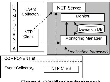
As shown in Figure 1, the dynamic verification framework that we have extended consists of a monitoring manager, a monitor, a Network Time Protocol (NTP) server, and communicates with different event collectors attached to the components of the system that is being monitored.
The monitoring manager has responsibility for initiating, coordinating and reporting the results of the monitoring process. Once it receives a request for monitoring a specific set of properties, the manager checks whether it is possible to monitor them and, if it is, it sends the properties to be checked to the monitor, and starts listening to events which are generated by different types of external event collectors. These events are received via TCP/IP sockets and sent to the monitor.
[image:3.612.61.277.500.660.2]After receiving events from the manager, the monitor checks whether they violate any of the properties given to it. The monitor is a generic engine for checking violations of EC formulas against a given set of runtime events. During monitoring, it also takes into account information about the state of a system that it derives from runtime events using a special type of EC formulas called assumptions (see Section 2.2). When a violation of a property is detected, the monitor records it in a deviation database which is polled regularly by the monitoring manager to retrieve detected deviations.
Figure 1 : Verification framework
The framework assumes that the components of the systems to be monitored have associated event collectors that can capture events during their operation and send
them to the monitor. When a collector captures a runtime event, it wraps it into an envelope with additional information including the source of the event (i.e., the component where it was captured) and a timestamp indicating when the event was captured at the component. To enable the synchronisation of event timestamps, the framework incorporates components that realise the Network Time Protocol [17] (i.e., a protocol based on the clock synchronisation scheme described in [12]). The implementation of this protocol allows event collectors to compute the difference of their clocks with the clock of the monitor at regular intervals. This difference is used to transform timestamps taken according to the clock of each collector into timestamps that express time in terms of the monitor’s clock. This is achieved by implementing an NTP client at each event collector and an NTP server at the machine that hosts the monitor, as shown in Figure 1. The NTP clients call the NTP server at regular intervals to synchronise their clocks with the clock of the server. The use of NTP can synchronise distributed clocks at a very high level of accuracy since recent versions of NTP (version 4) use a resolution of less than one nanosecond.
2.2 Specification of Properties
As indicated in Section 1, in our runtime monitoring framework the properties to be monitored are expressed in a language based on Event Calculus (EC) [19]. EC is a first-order temporal logic language which can be used for representing and reasoning about events and their effects over time. An event in EC is an occurrence that takes place at a specific instance of time (e.g., invocation of a system operation, receipt or dispatch of a message) and may have an effect. The effects of events are represented by fluents. Fluents are conditions which may change over time (e.g. a condition indicating that a system has received a message) and are initiated and/or terminated by events.
The occurrence of an event in EC is represented by the predicate Happens(e,t,ℜ(lb,ub)). This predicate denotes that an instantaneous event e occurs at some time t within the time range ℜ(lb,ub) (i.e., lb ≤ t ≤ ub) . The boundaries lb and ub that define time ranges are specified as linear expressions over time variables of Happens predicates in an EC formula of the form:
lb = l0 + l1 t1 + l2 t2 + … + ln tn ub = u0 + u1 t1 + u2 t2 + … + un tn
Given our focus on runtime system monitoring, the events we consider represent invocations of system operations, responses from such operations, or exchanges of messages between different system components. Thus, events have the following structure which captures the information required for monitoring such system interactions without affecting the overall expressiveness of the framework with respect to standard EC:
event(_id, _sender, _receiver, _status, _sig, _source) Event
Collector1
NTP Client
NTP Client
Monitoring Manager Monitor NTP Server C
O M P O N E N T
A
Deviation DB
Verification framework
COMPONENT B
In this structure:
_id is a unique identifier of the event
_sender is the identifier of the system component that sends the message represented by the event
_receiver is the identifier of the system component that receives the message represented by the event
_status is the processing status of an event (i.e. whether or not its processing has started when the monitor receives it)
_sig is the signature of the dispatched message or the operation invocation/response represented by the event, comprising the operation name and its arguments/result.
_source is the identifier of the component where the event was captured.
Fluents are defined as relations between objects of the form rel(O1, …, On) where rel is the name of a relation which associates the n objects O1, …, and On. The initiation or termination of a fluent f due to the occurrence of an event e at time t is denoted in EC by the predicates Initiates(e,f,t) and Terminates(e,f,t), respectively. An EC formula may also use the predicates Initially(f) and HoldsAt(f,t) to denote that a fluent f holds at the start of the execution of a system and at time t, respectively.
The rules to be monitored at runtime are specified in terms of the above predicates and have the general form body ⇒ head. The meaning of a rule is that if its body evaluates to true, its head must also evaluate to true. The Happens predicates in a rule which have no constraints for their lower and upper time boundaries are what we call “unconstrained” predicates. During the monitoring process, rules are activated by events that can be unified with the unconstrained Happens predicates in them. When this unification is possible, the monitor generates a rule instance to represent the partially unified rule and keeps this instance active until all the other predicates in it have been successfully unified with events and fluents of appropriate types or it is deduced that no further unifications are possible. In the latter case, the rule instance is deleted. When a rule instance is fully unified, the monitor checks if the particular instantiation that it expresses is satisfied.
An example of a rule that can be expressed in the EC language of our framework is given by the formula below:
Rule 1: ∀ _eID1,_C1,_C3:String; t1:Time
Happens(e(_eID1,_C3,_C1, REQ, authorise(),
_C3),t1,ℜ(t1,t1)) ⇒∃ _eID2:String ; t2:Time
Happens(e(_eID2,_C3,_C1, REQ, authorise(),
_C1),t2,ℜ(t1+1,t1+10))
This rule states that when an event e(_eID1,_C3,_C1, REQ, authorise(), _C3),t1,ℜ(t1,t1)) representing a call of the operation authorise() in a component _C1 by a component _C3 is dispatched, it must be followed by an event e(_eID2, _C3, _C1, RES, authorise(), _C1)
represening the receipt of the call by _C1 in no more than 10 time units after the dispatch of call. Thus, Rule 1 expresses a bounded availability property for the communication channel between the component _C3 and other components of the system (_C1) since it requires that the requests generated by _C3 are transmitted within a bounded time period.
The unconstrained predicate in this rule is the predicate Happens(e1C3,t1,ℜ(t1,t1))1, since the lower and upper bounds of its time variable are defined without any references to other time variables in the rule. Thus, at runtime, new instances of Rule 1 will be generated as soon as an event that can be unified with this predicate is received. Each of these rule instances will remain alive until it is fully unified or until no further unification of an event representing the receipt of a response of the call dispatched by _C3 in the rule instanceispossible.
Note that, as in the above example, our framework requires all the constrained predicates in a rule to have time variables with constrained upper bounds. This is to ensure that rules can be verified. For example, if the Happens predicate for e2C1 in the head of Rule 1 did not
have an upper bound, then its absence would never cause the monitor to flag the rule as violated, since the monitor would always wait for some e2C1 event at some point in
the future.
3.
COMPUTING LIFETIME OF EVENTS
As we discussed in Section 1, the problem that arises with the use of events which are generated by distributed sources is two-fold: firstly we need to synchronise the clocks of the different event sources so that the timestamps of the events that they generate can be comparable to each other and secondly we need to know until when we need to store a particular event in order to be able to reason about the system state and check rules. The clock synchronisation that is performed through the use of the Network Time Protocol (NTP) by our framework solves the first problem but not the second.To appreciate the second problem, consider Rule 1, assuming without loss of generality that _C3 and _C1 denote both the source of the event and the clock of the source system component where the event was captured. As the occurrence of events of type e1
C3
in Rule 1 is unconstrained, events of this type can instantiate the rule during monitoring. Unlike them, events of type e2C1 are
temporally constrained by e1 C3
events in the rule and cannot, therefore, create new instances of the rule; they can only be unified with existing rule instances.
1
e1C3 is an abbreviated reference to the event e(_eID1,_C3,_C1, REQ, authorise(), _C3), in which the subscript denotes to the event ID and
Thus, if the monitor receives an event of type e2C1, in
addition to unifying it with all the current instances of Rule 1, it must keep it until there is no possibility to receive an e1
C3
event that could be correlated with e2 C1
through Rule 1. This is necessary since if e2C1 is dropped
and later the monitor receives an e1C3 event with an earlier
timestamp than e2 C1
, it would report a false violation of Rule 1. The possibility of e1C3 and e2C1 events arriving at
the monitor in the opposite order of their occurrence arises due to different (and dynamically changing) communication delays in the channels that connect C1 and
C3 with the monitor or even attacks in these channels that
can cause the loss of events. Whilst keeping events of type e2C1 in this case is necessary for the soundness of the
monitoring results, the monitor must also ensure that it keeps these events only for the maximum time that is necessary for the soundness of the results. This is because if the monitor keeps them longer the size of its event store will increase monotonically with a deteriorating effect on both the space and time required for monitoring. The maximum time point until when events e2
C1
would need to be kept by the monitor, in this example, can be established by finding the maximum value of the time variable t1 of e1C3 events that satisfies the constraints: (1) t1 ≤ t2−1 and
(2) t2 ≤ t1+10.
In general, for a rule with n+1 Happens predicates, there will be 2n+1 such inequalities to solve. This is because one of the rule predicates is unconstrained (the one firing the rule), the remaining Happens predicates contribute two inequalities each, and we need an extra equality to establish the exact value for the time variable of the event in question (t2 in our previous example with the e2C1 events).
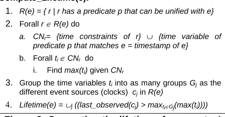
Figure 2 shows the algorithm for computing the lifetimes of an event. According to this algorithm, when an event e occurs, the set R(e) of rules which have predicates that can be unified with the event e is determined (this set includes rules that have event types which are the same as the type of e or supertypes of it). The set R(e) will include rules that may specify time constraints for the event that cannot be fully evaluated yet. Subsequently, the constraints of each rule in R(e) are identified and expanded with an equality expressing that the time variable of the predicate of the rule that has been unified with e is equal to the timestamp of e (step 2.a). Given the time constraint set that results from this process, the algorithm computes the maximum possible value for each of the time variables of the rule using the Simplex method [8] (step 2.b.i). Subsequently, it groups the different time variables according to the clock of the event source they are related to (step 3), and generates a set of all the conditions (Lifetime(e)) for computing the upper bound of the lifetime of e (step 4). A condition in Lifetime(e) states that e won’t be needed after the last event that is seen from a channel which is relevant to e has
a timestamp (last_observed(cj)) that is greater than the maximum possible value of the time variables grouped in this channel’s group (see condition last_observed(cj)> maxti∈Gj(max(ti))). The reason for using the timestamp of the last event that has been observed from a clock in the evaluation of the Lifetime(e) conditions is because events are communicated to the monitor through TCP/IP sockets which guarantee a FIFO transmission within the same component (clock)-monitor channel. The conditions in Lifetime(e) determine the lifetime of e since when their conjuction becomes true, the lifetime of e will expire.
Compute_Lifetime(e):
1. R(e) = { r | r has a predicate p that can be unified with e}
2. Forall r ∈ R(e) do
a. CNr= {time constraints of r} ∪ {time variable of
predicate p that matches e = timestamp of e}
b. Forall ti ∈ CNr do
i. Find max(ti) given CNr
3. Group the time variables ti into as many groups Gj as the
different event sources (clocks) cj in R(e)
[image:5.612.319.550.223.343.2]4. Lifetime(e) = ∪j ((last_observed(cj) > maxti∈Gj(max(ti))))
Figure 2: Computing the lifetime of an event – I
In our previous example, if Rule 1 is the only rule that is being monitored and an event of type e2C1 is observed at
t2=10, step 1 will produce the set R(e2C1) = {Rule-1}, step 2.a will produce CNr = {t1 ≤ t2−1, t2 ≤ t1 + 10, t2 = 10}, step 2.b.i will produce the solutions max(t1)=9 and max(t2)=10 by finding the maximum value of t1 for which the constraints in CNr are satisfied, and step 3 will produce two groups of time variables {t1} and {t2}, for the two clocks C1 and C3, respectively. Finally, in step 4, the
lifetime constraint set for e2C1 will be established as:
Lifetime(e2C1) = {(last_observed(C1)>10), (last_observed(C3) > 9)}.
coming from the same clock need to be grouped together, as done in step 3 of the algorithm.
Note that at this step, the algorithm of Figure 2 assumes that the clocks/sources of the events in the rules are fully specified when a rule is matched with an incoming event. In the example of Rule 1 this is the case, since the sender of an event e2
C1
(i.e. C3) is also the source of events e1C3. Thus, when Rule 1 is matched with an e2C1
event, the identity of C3 becomes known. However, there might be cases where the exact source of events that could potentially be matched with a rule is not known after the rule is matched with arrived events. Consider, for instance, the following rule:
Rule 2:
∀ _eID1, _eID2, _U: String; _C1,
_C3: Terminal; _C2: Component; t1, t2:Time Happens(e(_eID1,_C1,_C2, REQ, login(_U,_C1),
_C1),t1,ℜ(t1,t1)) ∧
Happens(e(_eID2,_C3,_C2, REQ, login(_U,_C3),
_C3),t2,ℜ(t1,t2)) ∧ _C1 ≠_C3 ⇒∃ _eID3: String; t3:Time Happens(e(_eID3,_C1,_C2, REQ-A, logout(_X,_C1),
_C1),t3,ℜ(t1+1,t2-1))
This rule requires that if a user _U logs in to a system _C2 from a terminal _C1 and later he/she logs in again from a different terminal _C3, he/she must have logged out from the former terminal before the second login. The rule effectively monitors cases where users are logged in from different terminals at the same time. When an event e(_eID2,_C3,_C2, REQ, login(_U,_C3), _C3) (or e2C3 in
our abbreviated form) arrives at the monitor, its lifetime will need to be estimated in reference to the maximum possible values of time variables t1 and t3. In this case, however, the algorithm of Figure 2 does not work, since at step 3 it is not known which other terminals the user of e2C3 may be using or, equivalently, which source clocks
should be associated with the time variables t1 and t3.
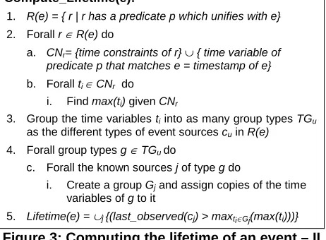
Compute_Lifetime(e):
1. R(e) = { r | r has a predicate p which unifies with e} 2. Forall r ∈ R(e) do
a. CNr= {time constraints of r} ∪ { time variable of
predicate p that matches e = timestamp of e}
b. Forall ti ∈ CNr do
i. Find max(ti) given CNr
3. Group the time variables ti into as many group types TGu
as the different types of event sources cu in R(e)
4. Forall group types g ∈ TGu do
c. Forall the known sources j of type g do
i. Create a group Gj and assign copies of the time
variables of g to it
[image:6.612.63.294.505.675.2]5. Lifetime(e) = ∪j {(last_observed(cj) > maxti∈Gj(max(ti)))}
Figure 3: Computing the lifetime of an event – II
To deal with such cases, we use an extension of the algorithm, shown in Figure 3. The extended algorithm
initially groups time variables into groups corresponding to the types of the event sources that are associated with them in the rules. Then, for each of the source type groups, it finds all the sources of the particular type that are known to the system, creates different groups for them and assigns copies of the time variables of each source type to each of the source groups that were generated from the type. Thus, if it is known that the system that is being monitored with Rule 2 has 3 terminals, the algorithm of Figure 3 will create different variable groups for each of these terminals and assign copies of the time variables t1 and t2 to each of these groups.
Having computed the Lifetime(e) constraint set, upon the arrival of an event e at runtime we use it to compute a vector with the maximum time values for e with respect to the different clocks related to it. For the ongoing example of Rule 1, the vector of e2C1 would be < 10, 9 >. The event
and its vector are then stored in the database of the monitor. Also, when a new event arrives at it, the monitor checks if the lifetime of some other events which depend on the clock of the new event has expired. The above process is shown in Figure 4.
1. Observe an event e
2. Update the global vector of observed clock values 3. Lifetime(e) = Compute_Lifetime(e)
4. Store e in the DB with its vector of different clock limits 5. Remove events from the DB if their clock limits have been
exceeded
Figure 4: Using event lifetimes
4.
RELATED WORK
Forms of dynamic verification have been developed and investigated in the context of program verification, safety critical, and service centric systems.
monitoring of [9] on the other hand does not support fluents or general expressions for time and does not clarify how the bound of the size of the event histories is decided. Event correlation has also been considered in [18] where event observers are produced as transducer automata recognizing and rewriting the input events. Compared to our framework, the approach in [18] does not support fluents or metric time.
The extension of the framework in [20] with the capabilities described in this paper makes it possible to verify complex properties, based on events captured from distributed sources, thus, exceeding the capabilities of other approaches.
5.
CONCLUSIONS
In this paper we have presented extensions of the monitoring framework described in [20] that render it applicable to multi-clock distributed systems. Our extensions address two of the problems of distributed systems monitoring: (1) the need for synchronizing the clocks of different event sources so that the events they emit can be correlated, and (2) the estimation of the lifetime of events within the monitor in order to ensure that unknown transmission delays of other events that may need to be correlated with them will not affect the monitoring process. To address the first of these problems, we have incorporated an implementation of the NTP protocol in our framework. To address the second problem, we compute the maximum lifetime of an event by identifying, the constraints between the time variable of the event and time variables of other events that co-exist with it in rules and solving these constraints to find the maximum possible lifetime for the event using the Simplex method (see [12] for full details).
One possible optimisation of our solution is to statically solve all the linear constraint systems at initialisation, so as to only need to instantiate the specific values of the different timestamps associated with a new event and its related rules when the event arrives, instead of solving the corresponding linear system each time. This would require a symbolic solution of the linear constraints system instead of the more straightforward numerical solution which we currently employ. For this reason we have decided against the symbolic solution in the current implementation, and intend to examine this option once we have gained more experience with the behaviour of the current implementation in a distributed setting.
6.
ACKNOWLEDGEMENTS
This work has been funded by the European integrated research project Serenity (FP6-IST-2006-27587).
7.
REFERENCES
[1] Adler I, et al. "An Implementation of Karmarkar's Algorithm for Linear Programming". Mathematical Programming, 44: 297–335, 1989.
[2] Ghezzi C., Guinea S., Runtime Monitoring in Service Oriented Architectures, In Test and Analysis of Web Services, (eds) Baresi L. & di Nitto E., Springer, 237-264, 2007.
[3] Barringer, H., Goldberg, A., Havelund, K., Sen, K. “Rule-Based Runtime Verification”, 5th International Conference on Verification, Model Checking, and Abstract Interpretation (VMCAI’04), 2004.
[4] Chen, F., Rosu, G. “Towards Monitoring-Oriented Programming: A Paradigm Combining Specification and Implementation”. In Electronic Notes in Theoretical Computer Science, 89(2), 2003.
[5] Clarke, E.M., Grumberg, O., Peled, D. “Model Checking”. MIT Press 1999
[6] D'Amorim, M., Havelund, K. “Event-based runtime verification of Java programs”, Proc. of 3rd Int. Workshop on Dynamic Analysis, 2005.
[7] Feather M. S., Fickas S., Van Lamsweerde A., Ponsard C. “Reconciling System Requirements and Runtime Behaviour”, Proc. of the 9th Int. Workshop on Software Specification & Design, 1998.
[8] Gale D. “Linear programming and the simplex method”. Notices of the AMS, 54(3):364–369, Mar. 2007.
[9] Jahanian, F., Rajkumar , R., Raju, S. C. V. “Runtime Monitoring of Timing Constraints in Distributed Real-Time Systems”. Real-Time Systems 7(3):247-273, Nov. 1994 [10]Havelund, K., Roşu, G. “An Overview of the Runtime
Verification Tool Java PathExplorer”, In Formal Methods in System Design, 24(2):189-215, 2004.
[11]Karaoman, M., Freeman J. “jMonitor: Java runtime event specification and monitoring library”. Proc. of 4th Workshop on Run-time Verification, 2004.
[12]Mahbub K., Spanoudakis G., Kloukinas C., “V2 of dynamic validation prototype”. Deliverable A4.D3.3, SERENITY Project, http://www.serenity-forum.org. [13]Marzullo K., Owicki S. “Maintaining the time in a
distributed system”. ACM SIGOPS Operating Systems Review, 19(3):44–54, July 1985.
[14]Mills D. L. “Network time protocol (version 3)”. RFC 1305c, Network Working Group, Internet Engineering Task
Force (IETF), 1992.
http://www.ietf.org/rfc/rfc1305.txt?number=1305.
[15]Mok, A. K., Liu, G. “Efficient run-time monitoring of timing constraints”. In Real-Time Technology and Applications Symposium, 1997
[16]Nelson, S., Pecheur, C. “V&V for advanced systems at NASA”, TASK NO: 10 TA-5.3.3 (WBS 1.4.4.5.3), prepared for Northrop Grumman Corp,2002
[17]NTP, www.ntp.org
[18]Sanchez, C., Sankaranarayanan, S., Sipma, H., Zhang, T., Dill, D., Manna, Z. “Event Correlation: Language and Semantics”, Proc. of Embedded Software (EMSOFT), LNCS 2855: 323-339, Oct. 2003
[19]Shanahan M. P. “The event calculus explained”. In Artificial Intelligence Today, Lecture Notes in Artificial Intelligence, 1600:409–430, 1999.