http://pil.sagepub.com/
and Applications
Engineers, Part L: Journal of Materials Design
http://pil.sagepub.com/content/225/3/195
The online version of this article can be found at:
DOI: 10.1177/0954420711402877
195 originally published online 13 June 2011
2011 225:
Proceedings of the Institution of Mechanical Engineers, Part L: Journal of Materials Design and Applications
C Walker
stabilization of large-scale fabrications
A theoretical review of the operation of vibratory stress relief with particular reference to the
Published by:
http://www.sagepublications.com
On behalf of:
Institution of Mechanical Engineers
can be found at:
Applications
Proceedings of the Institution of Mechanical Engineers, Part L: Journal of Materials Design and
Additional services and information for
http://pil.sagepub.com/cgi/alerts
Email Alerts:
http://pil.sagepub.com/subscriptions
Subscriptions:
http://www.sagepub.com/journalsReprints.nav
Reprints:
http://www.sagepub.com/journalsPermissions.nav
Permissions:
http://pil.sagepub.com/content/225/3/195.refs.html
Citations:
What is This?
- Jun 13, 2011
OnlineFirst Version of Record
- Jul 7, 2011
Version of Record
A theoretical review of the operation of vibratory stress
relief with particular reference to the stabilization of
large-scale fabrications
C Walker
Department of Mechanical Engineering, University of Strathclyde, Glasgow G1 1XJ, UK. email: [email protected]
The manuscript was received on 10 January 2010 and was accepted after revision for publication on 15 February 2011.
DOI: 10.1177/0954420711402877
Abstract: Vibratory stress relief (VSR) is widely used on large welded fabrications to stabilize the structures so that they do not distort during further machining or during operational duty. The level of applied stress achieved during VSR on such structures is only 510 per cent of the yield stress. It is, therefore, not obvious how these applied loads come to modify the level of residual stress. It is suggested here that the reason for the success of VSR applied to large fabri-cations lies (a) in the origin of the residual stresses and (b) in the partial relief of these residual stresses by the initiation of the transformation of retained austenite particles (in the size range from 1 to 25mm) by the movement of dislocations into positions that are favourable for the nucleation of martensite embryos. The shear deformation associated with the transformation of retained austenite into martensite will reduce the residual stress field to the point where the stability of the structure may be assured.
Keywords: vibratory stress relief, retained austenite, phase transformations, residual stress, constraint
1 INTRODUCTION
All structures contain residual stresses. These may interact with service loads to distort or crack the structure. Accordingly, the control of residual stresses is a matter for concern. In the main, the control of residual stresses is accomplished by careful design, choice of materials, and thermal stress relief. Since it was first reported in 1943 [1], the use of vibration to modify residual stresses (vibratory stress relief VSR) has been repeatedly proposed as an alternative to thermal stress relief, and is widely used to this day. In general, VSR is applied to a structure by means of an out-of-balance weight driven by an electric motor. This is clamped to the structure and the frequency of the motor is increased until a resonance is reached. The structure will be supported on rubber pads placed at points where the nodes in the vibration pat-tern will occur. The process is monitored by noting
the reduction in the resonant frequency of the struc-ture and is held to be complete when the resonant frequency is stable.
While there is an ample body of work relating to the satisfactory operation of VSR as a means of stabilizing fabrications, research studies set up to investigate VSR have not progressed greatly since Dawson and Moffat [2] indicated their belief in 1980 that ‘the various research investigations, aimed at assess-ing and explainassess-ing the process, have arrived at a vari-ety of conclusions ranging from open scepticism to guarded optimism.’
The range of materials that have been studied include low-carbon and alloy steels and aluminium alloys, while the structures range from small labora-tory specimens to castings and fabrications weighing many tonnes [36].
essence, the details of the material have been regarded as of passing importance and this has contributed greatly to the diversity of the outcomes, since even materials which are of the same nominal chemical composition may have quite different ther-momechanical processing histories, and in conse-quence, the grain size and phase composition may be different.
Nevertheless, it must be said that VSR has had suc-cess in applications where it would be difficult to achieve the same ends with thermal heat treatment. Recently, the welded rails for the Maglev high-speed train, built to enable rapid access from Shanghai to its airport, have been fabricated and given a VSR treat-ment to ensure that they will remain flat and stable for the working life of the railway [7]. The relevant residual stresses were reduced by up to 40 per cent in the fine-grained, normalized low-carbon steel (StE355). In this application, VSR may be said to have been entirely satisfactory. The use of thermal stress relief was not considered desirable, as the rails were given a spray coating of aluminium to resist corrosion, and also the size of the rail sections at 3 m of length was larger than the available anneal-ing facilities.
On the other hand, a careful study by a DutchGerman group which set out to evaluate the potential for VSR to (a) reduce residual stresses and (b) measure how this affected the subsequent fatigue life of the components, came to the conclusion [8]
that VSR was not at all effective in prolonging the fatigue life of the welded T-joints that were the sub-ject of the investigation. The material concerned steel alloy StE 690 was chosen as having a high yield strength (774 MPa) in order to obtain high levels of residual stress in the welded components. In this case, the thermal stress relief process was more successful in controlling the residual stresses. A comment was made by the suppliers of the vibra-tion equipment that the specimensat 50 kgwere at the lower end of the size range that were suitable for treatment by VSR.
These two examples show the diversity of outcome expected of the technique first, it was stability that was the aim; second, it was an extension of fatigue life.
2 THEORY OF THE OPERATION OF VSR
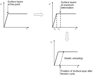
In its simplest form, VSR may be understood by refer-ring to Fig. 1, in which a beam is considered. Initially, the outer layer on each side of the beam is presumed to be in a state of residual tension, parallel to the length, equivalent to the yield stress in the material; as the beam is bent, the outer layer on the outside of the curve follows a load path that takes it along the plastic section of the stressstrain curve. As the beam is released, the outer layer will be unloaded elasti-cally, so that when the beam is straight, the outer layer is in a state of zero stress. The top of the beam
[image:3.595.126.457.495.758.2]has been stress-relieved, since if the bending is repeated, the top element will simply load and unload elastically.
The element on the inside of the curve, on the other hand, will be unaffected by the compressive loading it will unload elastically. However, if the bending is reversed, it will now be on the outside of the curve, and follow the same strain path of plastic yielding followed by unloading.
Thus far, it would appear that in real materials, rather than the artificial situation envisaged above, a few cycles of vibration should decidedly reduce the levels of residual stress in a component, even if the state of stress is more complex than that consid-ered here. In essence, the residual stresses and the vibration-induced loads have combined to cause local yielding that has reduced the global state of stress. This has been named the plasticity model for the operation of VSR. A similar conclusion was reached by Dawson and Moffat [2] who also showed that there was a threshold stress below which no effect was observed, reaching a situation where at an applied cyclic load of 0.85 of the 0.2 per cent yield stress, one could completely relieve a residual stress of 0.4 of the 0.2 per cent yield stress. The method they used to induce the residual stresses reverse bending did not allow them to evaluate a residual stress level higher than 0.4 of the 0.2 per cent yield.
The existence of a threshold effect was also con-firmed [9] by a study of residual stress in mild steel induced by a precisely controlled rolling process. This gave a residual stress profile similar to that postulated in Fig. 1, with a thin surface layer close to the material yield point, and the body of the specimen under a low level of residual compressive stress. At levels of applied stress below 50 per cent of the yield, there was no evidence of a VSR effect, even after 10 000 cycles of applied loading. Higher levels of applied vibrating stress were effective in reducing the levels of residual stress in these specimens (Fig. 2).
If these two studies of small-scale specimens are summarized, it may be seen that the plasticity model of the operation of VSR is basically confirmed, with the caveat that a substantial threshold effect does exist.
However, if the experience obtained with larger specimens is reviewed, it is found that the plastic-ity model no longer has the power to explain the observed behaviour.
As an example, the stress levels applied to the 18-m long beam described in Adamset al.[3] (Fig. 3) may be evaluated.
From the acceleration measured at the extreme end of the beam, it may be calculated that the maximum stress induced at the midspan was no greater than 10 per cent of the yield stress in the material (mild steel AISI 1018 yield stress, 300 MPa). This is well
Fig. 2 The effect of vibration on residual stress induced by rolling (1 per cent reduction) in a sample of mild steel
Note that there is no effect till the induced stress reaches 250 MPa
[image:4.595.151.466.490.732.2]below the threshold measured on the smaller speci-mens, and if the same conditions were to apply, there should have been no VSR effect observed. In fact, the VSR was successful in stabilizing the whole central section of the beam against distortion despite further radical machining processes the removal of more
than 1000 kg of material. This experience has been replicated in other applications, including a large tur-bine generator retainer ring (Fig. 4). Further examples may be found in Mordfin [4].
One may conclude that there is a difference between the way that VSR operates in small, labora-tory-scale specimens, and the multitonne compo-nents where it has been found to be a viable and successful process. It is the central hypothesis of this article that the difference lies in the way that the residual stresses are generated in the two cases.
3 ORIGINS OF RESIDUAL STRESS IN FERROUS ALLOYS
If the small-scale specimens used by Dawson and Moffat [2] and Walkeret al.[9] are considered, these both derive from cold plastic deformation from reverse bending in the case of Dawson and Moffat, and from rolling in the case of Walkeret al.The resid-ual stresses arise from the intense shearing of the material, with consequent dislocation entanglements and grain deformation.
The origins of the residual stresses in welded com-ponents is quite different in that they arise from dif-ferential thermal contraction and the progress of the phase transformations during the cooling of the material after welding (Fig. 5). During the later stages of cooling, the levels of residual stress rise rapidly due to the thermal contraction of ferrite, which has a large coefficient of thermal expansion, and a high yield stress [10,11] (Fig. 6).
Fig. 4 Hydropower wicket gate bearing ring during VSR treatment. Material cast steel, with welded repair. The ring has an internal diameter of 5.6 m. Approximate weight is 40 tonnes. Photograph courtesy of the VSR Group of Airmatic Inc
[image:5.595.40.270.192.411.2] [image:5.595.125.451.515.734.2]Due to the mass of the component, the rate of cool-ing is slower in larger specimens than in small-scale specimens, especially if they have been preheated to minimize the thermal shrinkage stresses, giving
ample time for the low-temperature equilibrium phases to develop, and for the residual stresses to arise by these mechanisms. As an example of the timescale in large componentsin this case a turbine Fig. 5 CCT diagram for a typical low-carbon steel
Fig. 6 The development of residual stresses by the differential expansion of phases during cooling (after Bhadeshia [10])
[image:6.595.143.466.89.483.2] [image:6.595.144.472.490.671.2]rotor Shi et al. [12] found a cooling time of 3.5 h from 840C to 100C, whereas a prismatic bar of dimensions 55 mm10 mm10 mm cooled through the same range of temperature in 30 s [13].
In fact, this mechanism, whereby the final level of residual stress may be largely derived from the phase transformations, explains why some fabrications resist post-weld heat treatment to reduce the residual stresses since the stresses arise from the cooling process itself, further heating and cooling will not necessarily reduce the room temperature residual stresses.
3.1 Effect of constraint on the residual stresses
In large components, it is to be anticipated that the degree of constraint will be high, since the cooler outer layers will exert a compression on the still-hot inner layers of the structure. The dependence of the residual stress state on the state of constraint has been evaluated for a TRIP steel by Berrahmoune et al. [14] in a study that showed that the retained austenite could end up in a state of stress ranging from 275 MPa in tension to 75 MPa in compression before being strained.
The detailed operation of these mechanisms will depend upon the actual alloy composition, and upon the geometry of the component. In a study of small-scale welded specimens, Munsi et al. [15, 16] measured the effect of VSR on low-carbon steel speci-mens 3 mm thick and 20 mm wide, with a weld bead laid down on one side of the specimen at midspan. The residual stresses were measured by X-ray diffrac-tion and were found to be insensitive to the applied vibration at stress levels below the yield stress in the base material. In these specimens, the rate of cooling was such that the austenite was not stabilized by the combination of carbon diffusion and the subdivision of the austenite grains, (see section 6 for a discussion of this effect) and so the low-stress mechanism could not operate. VSR was only effective in reducing the residual stresses according to the plasticity model i.e. after the application of vibratory stresses that were a large fraction (70100 per cent) of the local yield stress.
4 REACTION OF THE RESIDUAL STRESS PATTERNS TO APPLIED VIBRATION
4.1 Cold-deformation-induced residual stress
The two sets of specimens can now be differentiated by the way in which their residual stresses were induced. The specimens that were cold-deformed were unaffected by applied vibration until the local
applied stress exceeded the local yield strength of the material. A threshold effect was observed, and the application of stresses that were a large fraction of the yield stress was required for the residual stress regime to be altered.
4.2 Residual stress in large welded components
By contrast, in larger components where the residual stresses have arisen as a result of the slow cooling from the welded state, and the consequent differen-tial phase contraction, the residual stresses were reduced by low levels of applied stress in the range 210 per cent of the yield stress in the material. In this case, the definition of ‘large’ will depend upon the alloy, the detailed weld design, and the mechan-ical constraints that result from the geometry of the component.
5 RESIDUAL STRESS REDUCTION IN LARGE COMPONENTSREVISED THEORY
A situation is now reached where consideration may be given to the mechanism whereby VSR reduces the residual stress levels in the large components as described in section 1. It is possible to rule out a ther-mally activated process since the rate of diffusion at room temperature is very low [17, 18]. Bulk plastic flow, as observed in the specimens where the stress was induced by cold plastic work, may also be ruled out on the grounds that the applied stress levels are too low by a factor of 510.
It is proposed here that the mechanism depends upon the vibration creating nucleation sites for the transformation of retained austenite to martensite. When the austenite transforms, it does so by a shear mechanism that involves large strains, which in turn can act to reduce the residual stress field. Since no diffusion is involved, the transformation, once initi-ated, goes to completion almost instantly (the trans-formation front moves at the speed of sound). The details of the mechanism for the transformation are well known, and have been reviewed in depth [17,18].
recently, it has been shown by modelling that arrays of dislocations may be brought into alignment such that they will create favourable conditions for mar-tensite embryos to form [20] (Fig. 7).
5.1 Dislocation mobility
VSR is normally controlled by monitoring the fall in the resonant frequency of the structure that is being used for excitation. This fall is related to the mobili-zation of dislocations within the structure and the associated fall in the stiffness modulus, and is not related to the phase changes [9]. The VSR treatment is terminated when the resonant frequency is stable i.e. the process of mobilization of the dislocations has reached a limit. From a practical standpoint, this is both convenient and logicalthere is little to be gained from further prolongation of the treatment. In fact, Walkeret al.[9] showed that the resonant fre-quency shift reached a plateau after 10 000 cycles and remained stable for a further 250 000 cycles. This experimental experience shows that even low levels of applied alternating stress can mobilize dislocations in the manner required for them to create martensite nuclei.
5.2 Martensitic reaction
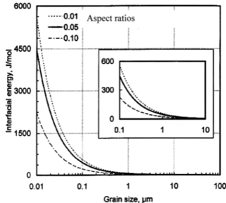
Briefly, then, the austenitemartensite transforma-tion proceeds when (a) a nucleus approximately 20 nm in diameter is present to allow the formation of a martensite embryo and (b) retained austenite which can transform is present, since austenite may be in a state of stability that ranges across the spec-trum from large grains that will transform readily (Fig. 8) to submicron grains which will not transform at all owing to the large surface strain energy that
begins to be significant at grain sizes below 0.1mm (Fig. 9, [21]). If it is postulated that the VSR operates to create nuclei by moving dislocations into the correct configurations it may be understood, how the process of VSR proceeds over many cycles of vibration, as there is an element of chance as to just when dislocation interactions will generate the cor-rect condition at each nucleus site i.e. all the retained austenite grains are not going to transform on the first cycle of applied stress.
Fig. 9 Stabilization of austenite during cooling inter-facial energy of the transform surface as a function of grain size in a 1.6 per cent carbon steel [17]
Fig. 8 Stabilization of austenite during cooling crit-ical grain size as a function of aspect ratio and martensite nucleus density
Fig. 7 The interaction of the two dislocations creates regions of tensile stress which are favourable for the creation of martensite embryos [18]
[image:8.595.326.555.239.444.2] [image:8.595.322.552.517.723.2] [image:8.595.61.291.578.736.2]For this to be accepted as a viable explanation of the observations in large structures, there are a number of points that need to be addressed as follows: (a) what evidence is there that there will be retained austenite at room temperature, despite the fact that this phase should transform well above room temperature and (b) how does vibration interact with the material to enable the austenite to transform in the absence of other driving forces?
6 STABILIZATION MECHANISMS OF RETAINED AUSTENITE
From an examination of the continuous cooling transformation (CCT) diagram for a typical low-carbon steel (Fig. 5), one may see that the high temperature phase austenite should transform com-pletely at temperatures well above ambient, even if the material is quenched. At rates of cooling found in large structures, the room temperature structure may be evaluated from the CCT curve, where it may be seen that the equilibrium structure will be a mixture of martensite, pearlite, ferrite, and bainite.
There are, however, several mechanisms that serve to stabilize the austenite so that it may be retained at ambient temperatures [21]. This topic has been dis-cussed in detail by Wang and van der Zwaag [21] with particular reference to the behaviour of TRIP steels. For the alloys commonly used for large-scale fabrica-tions (basically low-carbon steels), the principal sta-bilizing mechanism is the subdivision of the austenite grains into smaller and smaller units by the products of transformation, till at grain sizes below about 25mm, when the austenite grains cannot transform as they no longer contain nuclei for the martensite embryos (Fig. 8). This is a geometric effect, which was first observed by Turnbull and Vonnegut [22] in 1954, and has more recently been investigated by Bai et al. [23]. The density of martensite embrionic sites may be calculated [21], once the grain size reaches a diameter of 25mm; there are no longer enough embryonic sites for each grain to contain at least one, and the reaction ceases.
If further transformation is to take place in the small grains which are without nuclei, more nuclei need to be generated, since the energy barrier for nucleation is well above that which may arise from thermal fluctuations [17].
6.1 Carbon diffusion during cooling
Also, the slower rate of cooling in the larger structures allows time for carbon to diffuse out of the ferrite into the austenite. Higher carbon levels in the austenite grains act to inhibit transformation [21] by lowering
the temperature at which austenite will transform spontaneously to martensite [14].
6.2 Stress reduction during transformation
As each grain of austenite transforms, the energy released equilibrates with the energy stored in the surrounding crystal grains to reduce the local stress field. Since the energy released by the transformation is 12 orders of magnitude greater than the elastic energy stored in the material at yield, the transfor-mation of a small proportion of retained austenite will relieve the stresses in a large volume of steel. This effect has been modelled by Ferguson et al. [13], using the Dante simulation package, to the effect that the martensite transformation may gener-ate a stress of 400 MPa during the quenching and tempering of a prismatic bar of Pyrowear 53 steel alloy.
These stabilization mechanisms have been inves-tigated by Baiet al.[23] in a study where they cooled a Nb-microalloyed TRIP steel at two different cooling rates from a 400C holding temperature. The slower cooling rate (2C/s) resulted in retained austenite grains mostly larger than 2mm, while the faster cool-ing rate (10C/s) resulted in a retained austenite grain size below 1mm. The larger grains were rela-tively unstable, in that they transformed at low levels of applied strain, and so did not contribute to the TRIP effect as desired in that material. From the VSR viewpoint, it is the larger retained austenite grains which will transform, given the creation of a martensite embryo. The small grains are inhibited from transforming by the increasing relative impor-tance of the surface energy as the size decreases [21]. The stability of small grains of retained austenite has been confirmed by Jimenez-Meleroet al.[24]. They performed X-ray diffraction studies on a TRIP steel during cooling and were able to follow the transfor-mation of individual grains. Their work confirmed the hypothesis that size effect and carbon concen-tration work together to stabilize the austenite grains.
Modelling of welds [25,26] and of the interaction between diffusive and displacive transformations [27, 28] have shown that the development of the phase structure that arises does so as a result of a dynamic interaction between composition and ther-mal history that may not be evident from a consider-ation of the CCT curves alone (Fig. 5).
Bouville and Ahluwalia [27] have shown using GinsburgLandau theory how the phase transforma-tions in a model system are a matter of ongoing evolution owing to the interaction between the trans-formations that depend upon diffusion, and those that do not (the displacive transformations e.g. the martensite reaction), and that the observed mechanisms for the retention of austenite may be predicted from the thermomechanics of the lattice.
It may be concluded from these strands that the state of phase composition in large specimens is rad-ically different from those in small specimens, even when they have nominally been prepared by the same welding process, and that there will be quantities of retained austenite as a finely divided set of grains.
7 APPLICATION TO VSR
A revised theory for the operation of VSR was intro-duced earlier. The evidence for the necessary condi-tions for this theory to operate has been reviewed. The functioning of VSR will now be discussed in more detail.
It should be recalled first that all metals contain distributions of dislocations. Under the alternating stress field of the VSR process, these will be mobile, and will rearrange themselves within each grain and subgrain. It was first suggested by Olson and Cohen [19] in 1976 that dislocation cores could act as the necessary precursors for martensitic embryos. More recently, Li et al. [20] have shown using molecular dynamics modelling that arrays of dislocations do give rise to the conditions conducive to the nucle-ation of martensite. Once the martensite is nucleated, the transformation will propagate through the aus-tenite grain. VSR may be seen as a grain-by-grain stress reduction process, dependent upon the fact that some grains will transform immediately, while others will not transform until many cycles of applied stress eventually create the conditions for the crea-tion of a martensite nucleus.
The application of VSR to structures has to date been a matter of trial and error; however, given an alloy composition and the details of the welding pro-cess, it is now possible to predict the phase composi-tion that will result from a specific cooling regime. By this means, one may identify those structures which will respond readily to VSR, by computing the extent of retained austenite in the as-welded fab-rication and its state of stability.
8 CONCLUSION
There is a body of experimental evidence to show that large welded fabrications may be stabilized by the
application of resonant vibration which induces low levels of stress (in the range 510 per cent of the yield stress). The reduction in residual stress which is accomplished by the vibration cannot be explained in this case by the plasticity theory that has been developed to explain the operation of VSR in small specimens.
It has previously been shown that the martensite reaction may be stabilized so that small grains of aus-tenite may exist at room temperature. A revised theory of VSR has been proposed based around the concept that the vibration activates mobile dislo-cations, so that they move into configurations that promote the nucleation of martensite in these grains of retained austenite, allowing the austenite to transform. When the austenite transforms to mar-tensite, it undergoes a shear transformation which will act to reduce the local residual stress by interac-tion with the stress field imposed externally on the austenite grain. The use of VSR on large fabrications may then be seen to be related to the slow cooling rate of the structure, after welding, which promotes the stabilization and retention of the austenite. In smaller welded specimens, of the type used in laboratory investigations, the cooling rate is much higher, and the carbon does not have time to diffuse from the ferrite phase, which is a necessary step in the stabili-zation of the austenite grains. In specimens where the residual stresses are induced by cold working, there will be no retained austenite for the proposed mech-anism to operate, and so these specimens conform to the plasticity theory of VSR.
By the use of modelling software, it should now be possible to predict alloy compositions and process variables which would predispose a structure to the useful application of VSR.
!Authors 2011
REFERENCES
1 McGoldrick, R. T.andSaunders, H. S.Some experi-ments in stress relieving castings and welded struc-tures by vibration.J. Am. Soc. Naval Eng., 1943,55(4), 589609.
2 Dawson, R.andMoffat, D. G.Vibratory stress relief: a fundamental study of its effectiveness.J. Eng. Mater. Technol., 1980,102, 169176.
3 Adams, C. M., Berry, J. T., and Klauba, B. B. Productive applications of mechanical vibrations. In Trends in welding research 2005, Pine Mountain, Georgia, 1620 May 2005 (ASM International, Materials Park, Ohio), available from www.airmatic. com
4 Mordfin, L. (Ed.) Mechanical relaxation of residual stresses, ASTM STP 993, 1988 (American Society for Testing and Materials, Philadelphia).
5 Gnirss, G. Vibration and vibratory stress relief. Historical development, theory and practical appli-cation.Weld. World, 1988,26(11/12), 284291. 6 Munsi, A. S. M. Y. Investigation and validation of
vibratory methods for stress relief and weld condi-tioning. PhD thesis, University of Strathclyde, UK, 1999.
7 Rao, D., Ge, J.,andChen, L.Vibratory stress relief in manufacturing the rails of a Maglev system.Trans. ASME, J. Mf. Sci. Technol., 2004,126, 388391. 8 Sonsino, C. M., Muller, F., de Back, J.,andGresnigt,
A. M.Influence of stress relieving by vibration on the fatigue behaviour of welded joints in comparison to post-weld heat treatment.Fatigue Fract. Eng. Mater. Struct., 1996,19(6), 703708.
9 Walker, C. A., Johnstone, D., and Waddell, A. J. Vibratory stress relief an investigation of the underlying processes. Proc. IMechE Vol 222 Part E: J. Process Mechanical Engineering, 1995,209, 5158. 10 Withers, P. J.andBhadeshia, H. D. K. H.Residual stress. Part 2 Nature and origins. Mater. Sci. Technol., 2001,17, 366375.
11 Francis, J. A., Bhadeshia, H. K. D. H.,andWithers, P. J.Welding residual stresses in ferritic power plant steels.Mater. Sci. Technol., 2007,23, 10091020. 12 Shi, W., Zhang, X., and Liu, Z. Model of
stress-induced phase transformation and prediction of internal stresses of large steel workpieces during quenching.J. Phys. IV France, 2004,120, 473479. 13 Ferguson, B. L., Li, Z.,andFreborg, A. M.Modeling
heat treatment of steel parts. Comput. Mater. Sci., 2005,34, 274281.
14 Berrahmoune, M. R., Bervillier, S., Inal, K., Moulin, A.,andPatoor, E.Analysis of the martensitic trans-formation at various scales in TRIP steel.Mater. Sci. Eng. A, 2004,378, 304307.
15 Munsi, A. S. M. Y., Waddell, A. J.,andWalker, C. A. Modification of residual stress by post-weld vibra-tion.Mater. Sci. Technol., 2001,17, 601606. 16 Munsi, A. S. M. Y., Waddell, A. J.,andWalker, C. A.
Vibratory weld conditioning: treatment of speci-mens during cooling. Proc. IMechE Part L: J. Materials: Design and Applications, 2000, 214(3), 129138.
17 Porter, D. A.andEasterling, K. E.Phase transforma-tions in metals and alloys, 1988 (Van Nostrand Reinhold (Int.), New York).
18 Bhadeshia, H. D. K. H.Some phase transformations in steels.Mater. Sci. Technol., 1999,15, 2229. 19 Olson, G. B.andCohen, M.A general mechanism of
martensitic nucleation: Part I. General concepts and the FCC !HCP transformation. Metall. Trans. A, 1976,7(12), 1905.
20 Li, B., Zhang, X. M., Clapp, P. C.,andRifkin, J. A. Molecular dynamics simulations of the effects of defects on martensite nucleation. J. Appl. Phys., 2004,95(4), 16981705.
21 Wang, J.andvan der Zwaag, S.Stabilization mech-anisms of retained austenite in transformation-induced plasticity steel.Metall. Mater. Trans., 2001, 32 A, 15271539.
22 Turnbull, D.andVonnegut, J. A.Nucleation cataly-sis.Ind. Eng. Chem., 1952,44, 1292.
23 Bai, D. Q., di Chiro, A., and Yue, S. Stability of retained austenite in a Nb microalloyed Mn-Si TRIP steel.Mater. Sci. Forum, 1998,284286, 253266. 24 Jimenez-Melero, E., van Dyke, N. H., Zhao, L.,
Seitsma, J., Offerman, S. E., Wright, J. P., and van der Zwaag, S. Martensitic transformation of individual grains in low-alloyed TRIP steels.Scripta Mater., 2007,56, 421424.
25 Taljat, B., Radhakrishnan, B., and Zacharia, T. Numerical analysis of GTA welding process with emphasis on post-solidification phase transforma-tion on residual stress. Mater. Sci. Eng. A, 1998, 246, 4554.
26 Becker, M., Jordan, C., Lachhander, S. K., Mengel, A., and Renaud, M. Prediction and measurement of phase transformations, phase dependent proper-ties and residual stresses in steels, OSTI report no. 8550544, May 2005.
27 Bouville, M. and Ahluwalia, R. Interplay between diffusive and displacive phase transformations: time-temperature-transformation diagrams and micro-structures.Phys. Rev. Lett., 2006,97, 055701–14. 28 Lusk, M. T., Wang, W., Sun, X.,andLee, Y.-K.On the


![Fig. 6The development of residual stresses by the differential expansion of phases during cooling(after Bhadeshia [10])](https://thumb-us.123doks.com/thumbv2/123dok_us/1688644.122235/6.595.143.466.89.483/development-residual-stresses-differential-expansion-phases-cooling-bhadeshia.webp)