D. G. Hattingh et alii, Frattura ed Integrità Strutturale, 33 (2015) 382-389; DOI: 10.3221/IGF-ESIS.33.42
1
Multiaxial fatigue of aluminium friction stir welded joints:
preliminary results
D. G. Hattingh
Nelson Mandela Metropolitan University, Private Bag X6011, Port Elizabeth 6000, South Africa danie.hattingh@nmmu.ac.za
M. N. James
University of Plymouth, Drake Circus, Devon PL4 8AA, England, United Kingdom m.james@plymouth.ac.uk
L. Susmel
The University of Sheffield, Sheffield S1 3JD, United Kingdom l.susmel@sheffield.ac.uk
R. Tovo
University of Ferrara, via Saragat 1, 44100 Ferrara, Italy roberto.tovo@unife.it
ABSTRACT. The aim of the present research is to check the accuracy of the Modified Wöhler Curve Method
(MWCM) in estimating the fatigue strength of friction stir (FS) welded tubular joints of Al 6082-T6 subjected to in-phase and out-of-phase multiaxial fatigue loading. The welded samples being investigated were manufactured by equipping an MTS I-STIR process development system with a retracting tool that was specifically designed and optimised for this purpose. These specimens were tested under proportional and non-proportional tension and torsion, the effect of non-zero mean stresses being also investigated. The validation exercise carried out by using the generated experimental results allowed us to prove that the MWCM (applied in terms of nominal stresses) is highly accurate in predicting the fatigue strength of the tested FS welded joints, its usage resulting in estimates falling with the uniaxial and torsional calibration scatter bands.
KEYWORDS. Friction stir welding; multiaxial fatigue; critical plane.
INTRODUCTION
D. G. Hattingh et alii, Frattura ed Integrità Strutturale, 33 (2015) 382-389; DOI: 10.3221/IGF-ESIS.33.42
2
[image:2.595.88.502.228.377.2]also be used to join dissimilar metals and alloys that are difficult to be welded metallurgically. There has therefore been a substantial take-up of FS welding in structural manufacturing across a wide range of industrial sectors [1] including ship building [2], transportation [3], and aircraft [4]. In the case of the aircraft industry both the American Welding Society and NASA have recently published technical standards for friction stir welding of aerospace hardware fabricated from aluminium alloys [5, 6]. Whilst the fatigue behaviour of aluminium FS welded joints subjected to uniaxial cyclic loading has been studied in depth over the last two decades (see, for instance, Ref. [7] and references reported therein), examination of the state of the art suggests that no systematic theoretical/experimental work has been carried out so far in order to formalise and validate specific criteria suitable for performing the multiaxial fatigue assessment of this type of welded connections. In this complex scenario, this paper summarises a part of a large programme of work on the issue of multiaxial fatigue design for FW welded tubular structures.
Figure 1: Schematic of the tube welding system and final setup on the MTS I-STIRTM platform.
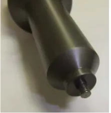
Figure 2: Retractable tool shoulder (10mm) and pin. Figure 3: Al 6082-T6 FS welded tubular specimen.
PIPE WELDING SYSTEM FOR FSW OF TUBES
Friction stir welding of tubes presented particular challenges in terms of pin plunge depth, support for the material during welding and arranging tool retraction as not to leave the typical plunge pin hole in the joint line after retracting the tool. An MTS I-STIR™ Process Development System (PDS) provided the foundation for this work, which involved incorporating a Helical SEW Worm Gear Motor with a tube support system for the welding process. This drive system control was integrated with that of the I-STIR platform to ensure optimal process control. Figure 1 shows a schematic of the worm gear drive and actual integration into the I-STIR platform.
An important consideration was the development of a small diameter shoulder retracting tool to match the small diameter thin wall tube samples. The retractable pin tool differs from the fixed pin tool in that the pin length can be adjusted during welding. This adjustability allows the welder to compensate for variable plate or component thicknesses, ensuring that the correct ligament between the tool tip and the backing plate is maintained. In addition, the tool tip can be retracted towards the end of the weld thus eliminating the pin exit hole. The elimination of the pin exit hole cannot be realized in all applications as the pin must be retracted over a minimum distance or at a rate that prevents the formation of defects. Figure 2 shows the final tool being developed and optimised with a 10 mm shoulder and threaded pin configuration.
Flange coupling SEW Helical Worm Gear Motor
[image:2.595.90.201.408.521.2] [image:2.595.271.531.411.519.2]D. G. Hattingh et alii, Frattura ed Integrità Strutturale, 33 (2015) 382-389; DOI: 10.3221/IGF-ESIS.33.42
3
Control of this additional fixture was integrated with that of the I-STIR platform. Via an iterative optimisation process the optimum values for the manufacturing process variables were determined. This allowed FS welds of high quality to be made in small diameter aluminium tubes. Figure 3 shows a typical Al 6082-T6 specimen manufactured by using this innovative FS welding technology. The FS welded tubular samples used to generate the necessary experimental results had outer nominal diameter equal to 38 mm and inner nominal diameter to 31 mm. Both the static and fatigue results were determined by testing samples in the as-welded condition.
This new FS welding technology was developed and optimised at the Nelson Mandela Metropolitan University (NMMU), South Africa.
BR=0, R=-1
Nf=1664764 cycles to failure
BR= 3 , R=-1, =0°
Nf=369237 cycles to failure
BR=1, R=-1, =0°
Nf=650684 cycles to failure
BR= 3 , R=-1, =90°
Nf=173954 cycles to failure
BR=0, R=0
Nf=1071840 cycles to failure
BR= 3 , R=0, =0°
Nf=501988 cycles to failure
BR=1, R=0, =0°
Nf=857370 cycles to failure
BR= 3 , R=0, =90°
[image:3.595.37.556.200.409.2]Nf=224230 cycles to failure
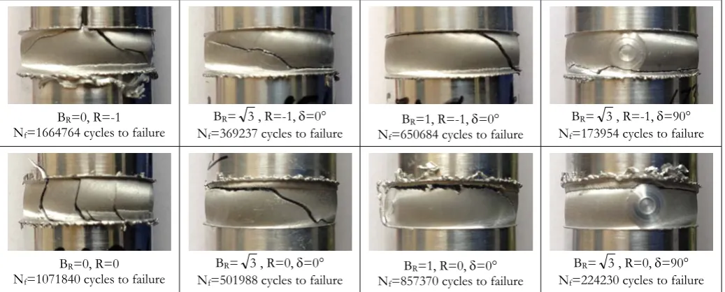
Figure 4: Examples of the observed macroscopic cracking behavior under biaxial fatigue loading (BR=nom,a/nom,a,
R=nom,min/nom,max=nom,min/nom,max, = out-of-phase angle).
EXPERIMENTAL DETAILS
Since welded joints’ mechanical properties are a suitable indicator of the overall weld quality, several static tests were run by testing the manufactured tubular joints under pure tension as well as under pure torsion. Irrespective of the type of applied loading, cracks were seen to initiate at the tip of the undercut resulting from the FS welding process. As a further check of the tensile strength, the axial strength was also determined at the University of Plymouth, UK, via microtensile quasi-flat specimens tested by using a Gatan Microtest 2000EW device. Such a systematic experimental investigation resulted in an average value of the ultimate tensile strength for FS welded Al 6082-T6 equal to 152 MPa, the axial static strength of the parent material being equal to 303 MPa. This allowed us to prove that the average efficiency of the manufactured welded joints (which is defined as the ratio of weld over parent plate tensile strength) approaches 0.5; this value compares well with the figure of 0.49 which is usually reported for FS welds in 3 mm thick plates of 6082-T6 [8]. The average static strength under torsion was seen to be equal to about 120 MPa.
The axial tests were performed at the University of Ferrara, Italy, by using an MTS 810 Mod. 318.25 servo-hydraulic axial testing machine. The samples were tested under a load ratio (R=nom,min/nom,max) equal to 0.1 as well as equal to -1.
The fatigue behaviour of the Al 6082-T6 FS welded specimens under biaxial loading was investigated at the University of Sheffield, UK, by using a SCHENCK servo-hydraulic axial/torsional testing machine equipped with two MTS hydraulic grips. Both the torsional and the biaxial tests were carried out under nominal load ratios equal to -1 and 0. The force/moment controlled tests were run under in-phase and 90° out-of-phase constant amplitude sinusoidal load histories. The pictures seen in Figure 4 show some examples of the typical cracking behaviours displayed by the Al 6082-T6 FS welded joints tested under biaxial loading.
D. G. Hattingh et alii, Frattura ed Integrità Strutturale, 33 (2015) 382-389; DOI: 10.3221/IGF-ESIS.33.42
4
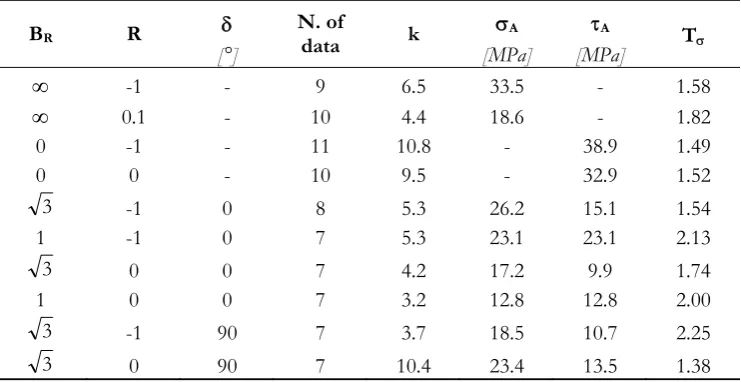
summarised in Table 1 in terms of SN curves. In particular, BR=nom,a/nom,a is the ratio between the amplitudes of the
axial and torsional nominal stress, R is the nominal load ratio (R=nom,min/nom,max=nom,min/nom,max), is the out-of-phase
angle, k is the negative inverse slope, A and A are the amplitudes of the axial and torsional endurance limits extrapolated
at NA=2106 cycles to failure, and, finally, T is the scatter ratio of the amplitude of the endurance limit for 90% and 10%
probabilities of survival. To conclude, it is worth observing that the fatigue curves summarised in Table 1 are determined in terms of nominal stresses referred to the annular section of the parent tube.
BR R N. of data k A A T
[°] [MPa] [MPa]
-1 - 9 6.5 33.5 - 1.58
0.1 - 10 4.4 18.6 - 1.82
0 -1 - 11 10.8 - 38.9 1.49
0 0 - 10 9.5 - 32.9 1.52
3 -1 0 8 5.3 26.2 15.1 1.54
1 -1 0 7 5.3 23.1 23.1 2.13
3 0 0 7 4.2 17.2 9.9 1.74
1 0 0 7 3.2 12.8 12.8 2.00
3 -1 90 7 3.7 18.5 10.7 2.25
[image:4.595.111.482.182.373.2]3 0 90 7 10.4 23.4 13.5 1.38
Table 1: Summary of the generated experimental results.
FUNDAMENTALS OF THE MODIFIED WÖHLER CURVE METHOD
The MWCM is a critical plane approach which predicts the number of cycles to failure via the maximum shear stress amplitude, a, as well as via the mean value, n,m, and the amplitude, n,a, of the stress normal to the critical plane. In this
setting, the critical plane is defined as that material plane experiencing the maximum shear stress amplitude, a [10]. The
combined effect of the relevant stress components relative to the critical plane is taken into account by means of stress index eff which is defined as follows [11]:
a a , n m , n eff
m
(1)
In definition (1), m is the so-called mean stress sensitivity index [10]. This index is a material property ranging in between 0 and 1 whose value has to be determined by running appropriate experiments [11]. Ratio eff is a stress quantity which is
sensitive not only to the presence of superimposed static stresses, but also to the degree of non-proportionality of the applied loading path [10].
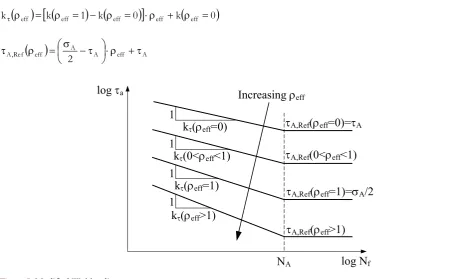
The way the MWCM estimates fatigue lifetime under multiaxial fatigue loading is schematically shown via the modified Wöhler diagram sketched in Figure 5. This log-log diagram plots the shear stress amplitude relative to the critical plane, a,
against the number of cycles to failure, Nf. By performing a systematic investigation based on numerous experimental
results generated under multiaxial fatigue loading [12-14], it was observed that fatigue damage tends to increase as eff
increases. This results in the fact that the corresponding fatigue curve tends to shift downward in the modified Wöhler diagram with increasing of eff (Fig. 5).
By taking full advantage of the classic log-log schematisation which is commonly adopted to summarise stress based fatigue data, the position and the negative inverse slope of any Modified Wöhler curve can unambiguously be defined via the following linear laws [10, 12-14]:
eff eff
D. G. Hattingh et alii, Frattura ed Integrità Strutturale, 33 (2015) 382-389; DOI: 10.3221/IGF-ESIS.33.42
5
eff a eff bf
Re
(3)
In relationships (2) and (3), k(eff) is the negative inverse slope, while Ref(eff) is the reference shear stress amplitude
extrapolated at NA cycles to failure (see Fig. 5). Constants, , a and b are material parameters to be determined
experimentally. In particular, by recalling that eff is equal to unity under fully-reversed uniaxial fatigue loading and to zero
under torsional cyclic loading [10], the constants in the MWCM’s calibration functions can directly be calculated as follows [10, 14]:
k
1
k 0
k
0
k eff eff eff eff eff (4)
A A eff Aeff f Re ,
A 2
[image:5.595.42.494.200.479.2] (5)
Figure 5: Modified Wöhler diagram.
In Eq. (4) k(eff=1) and k(eff=0) are the negative inverse slope of the uniaxial and torsional fatigue curve, respectively; in
Eq. (5) A and A are instead the endurance limits extrapolated at NA cycles to failure under fully-reversed uniaxial and
torsional fatigue loading, respectively.
It is worth pointing out here that the reference shear stress, A,Ref(eff), and the negative inverse slope, k(eff), to be used
to estimate lifetime under multiaxial fatigue loading are assumed to be constant and equal to A,Ref(lim) and to k(lim),
respectively, for eff values larger than an intrinsic threshold denoted as lim [10, 11]. This correction, which plays a role of
primary importance in determining the overall accuracy of the MWCM, was introduced to take into account the fact that, under large values of ratio eff, the use of the MWCM is seen to results in conservative estimates [15, 16]. According to the
experimental results due to Kaufman and Topper [17], such a high level of conservatism can be ascribed to the fact that, when micro/meso cracks are fully open, an increase of the normal mean stress does not result in a further increase of the associated fatigue damage. This important finding is taken into account by the MWCM via lim that represents the upper
bound for stress ratio eff [10, 16].
According to the theoretical framework briefly summarised above, the MWCM can be used to estimate fatigue lifetime by following the simple procedure described in what follows. Initially, the maximum shear stress amplitude, a, and the
effective critical plane stress ratio, eff, have to be determined at the assumed critical location [18, 19]. Subsequently,
according to the calculated value for eff, the corresponding modified Wöhler curve can directly be estimated from Eqs (4)
and (5). Finally, the number of cycles to failure under the investigated loading path is predicted via the following trivial relationship [10, 14]:
log Nf
log a
1
1
k(eff=0)
k(eff=1)
NA
A,Ref(eff=0)=A
A,Ref(eff=1)=A/2
1
k(0<eff<1) A,Ref(0<eff<1)
1
k(eff>1)
A,Ref(eff>1)
D. G. Hattingh et alii, Frattura ed Integrità Strutturale, 33 (2015) 382-389; DOI: 10.3221/IGF-ESIS.33.42 6 ) ( k a eff ref , A A f eff t ) ( N N
(6)
To conclude, it is worth observing that the MWCM has proven to be highly accurate in performing the multiaxial fatigue assessment of conventional welded joints when it is applied not only in terms of nominal [20-22] and hot-spot stresses [23, 24], but also along with the reference radius concept [24-27] as well as the Theory of Critical Distances [26-30].
1000 10000 100000 1000000 10000000 100000000
1000 10000 100000 1000000 10000000 100000000
[image:6.595.85.463.209.475.2]Nf [Cycles]
Nf,e[Cycles]
Axial loading, R=-1 Axial loading, R=0.1 Torsion, R=-1 Torsion, R=0
=0°, =√3, R=-1 =0°, =√3, R=0 =90°, =√3, R=-1 =90°, =√3, R=0 =0°, =1, R=-1 =0°, =1, R=0
PS=90%
PS=10%
Non-Conservative Conservative Torsional Scatter Band Uniaxial Scatter Band
FSW Aluminium Tubes
BR
BR
BR
BR
BR
BR
Run out
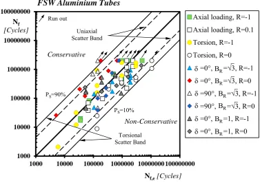
Figure 6: Accuracy of the MWCM in estimating the fatigue lifetime of the tested Al 6082-T6 FS welded joints.
VALIDATION BY EXPERIMENTAL DATA
In order to check the accuracy of the MWCM in estimating the fatigue lifetime of the tested FS welded joints, initially the calibration constants in Eqs (2) and (3) were determined, according to Eqs (4) and (5), by using the fatigue curves generated under fully-reversed uniaxial and torsional fatigue loading (see Table 1), i.e.:
4.3 10.8k eff eff (7)
eff 21.2 eff 38.9f
Re
[MPa] (8)
D. G. Hattingh et alii, Frattura ed Integrità Strutturale, 33 (2015) 382-389; DOI: 10.3221/IGF-ESIS.33.42
7
After calibrating the MWCM, multiaxial fatigue software Multi-FEAST (www.multi-feast.com) was used to systematically post-process all the experimental results that have been generated so far.
The experimental, Nf, vs. estimated, Nf,e, number of cycles to failure diagram reported in Figure 6 summarises the overall
accuracy which was obtained by using the MWCM to predict the lifetime of the FS welded tubular samples being tested. The chart of Figure 6 makes it evident that the use of the MWCM resulted in estimates falling within the wider scatter band between the two characterising the fully-reversed uniaxial and torsional fatigue curve used to calibrate the constants in the MWCM’s governing equations. It is possible to conclude by observing that the obtained level of accuracy is certainly satisfactory, since, from a statistical point of view, we cannot ask a predictive method to be more accurate than the experimental information used to calibrate the method itself.
CONCLUSIONS
The novel FS welding process developed via this project is seen to be capable of producing high quality FS welds in aluminium tubular joints. Such an advance in joining technology is anticipated to have high industrial impact.
The MWCM applied in terms of nominal stresses is a powerful design tool suitable for performing multiaxial fatigue assessment of FS welded connections.
More work needs to be done in order to formalise a comprehensive design approach suitable for designing FS welded joints against multiaxial fatigue loading by directly post-processing the local linear-elastic stress fields acting on the material in the vicinity of the crack initiation locations.
ACKNOWLEDGEMENTS
The Leverhulme Trust (www.leverhulme.ac.uk) is acknowledged for fully supporting the present research investigation (Project’s Reference Number: IN-2012-107).
REFERENCES
[1] S. Shah and S. Tosunoglu, Friction stir welding: current state of the art and future prospects, in: 16th World
Multi-Conference on Systemics, Cybernetics and Informatics, Orlando, Florida, 17-20 July 2012 (available at www.eng.fiu.edu). [2] K. J. Colligan, Friction stir welding for ship construction, Contract N0014-06-D-0048 for the Office of Naval Research, Concurrent Technologies Corporation, Harrisburg, PA, (2004) (available at www.nmc.ctc.com).
[3] Thomas, W. M. , Nicholas, E. D., Friction stir welding for the transportation industries, Mater. Design, 18 4/6 (1997) 269-273.
[4] Burford, D., Widener, C., Tweedy, B., Advances in Friction Stir Welding for Aerospace Applications, in: 6th AIAA
Aviation Technology, Integration and operations Conference, (2006), American Institute for Aviation and Astronautics. doi: 10.2514/6.2006-7730
[5] American National Standards Institute, AWS D17.3/D17.3M:2010, Specification for friction stir welding of aluminum alloys for aerospace hardware, American Welding Society, (2010).
[6] MSFC Technical Standard EM 30, MSFC-SPEC-3679, Process specification – welding aerospace hardware, National Space and Aeronautics Administration, (2012).
[7] Lomolino, S., Tovo, R., dos Santos, J., On the fatigue behaviour and design curves of friction stir butt-welded Al alloys, Int. J. Fatigue, 27 3 (2005) 305-316.
[8] Moreira, P. M. G. P., Santos, T., Tavares, S. M. O., Richter-Trummer, V., Vilaça, P., de Castro, P. M. S. T., Mechanical and metallurgical characterization of friction stir welding joints of AA6061-T6 with AA6082-T6, Mater. Design, 30 (2009) 180-187.
[9] Spindel, J. E., Haibach, E., Some considerations in the statistical determination of the shape of S-N cruves, in: R. E. Little and J. C. Ekvall (Eds.), Statistical Analysis of Fatigue Data, ASTM STP 744, (1981) 89–113.
[10] Susmel, L., Multiaxial Notch Fatigue: from nominal to local stress-strain quantities, Woodhead & CRC, Cambridge, UK, ISBN: 1 84569 582 8, (2009).
D. G. Hattingh et alii, Frattura ed Integrità Strutturale, 33 (2015) 382-389; DOI: 10.3221/IGF-ESIS.33.42
8
[12] Susmel, L., Lazzarin, P., A Bi-Parametric Modified Wöhler Curve for High Cycle Multiaxial Fatigue Assessment, Fatigue Fract. Eng. Mat. Struct., 25 (2002) 63-78.
[13] Susmel, L., Petrone, N., Multiaxial fatigue life estimations for 6082-T6 cylindrical specimens under in-phase and out-of-phase biaxial loadings, in: A. Carpinteri, M. de Freitas and A. Spagnoli (Eds.), Biaxial and Multiaxial fatigue and Fracture, Elsevier and ESIS, (2003) 83-104.
[14] Lazzarin, P., Susmel, L., A Stress-Based Method to Predict Lifetime under Multiaxial Fatigue Loadings, Fatigue Fract. Eng. Mat. Struct., 26 (2003) 1171-1187.
[15] Susmel, L., Tovo, R., Lazzarin, P., The mean stress effect on the high-cycle fatigue strength from a multiaxial fatigue point of view, Int. J. Fatigue, 27 (2005) 928-943.
[16] Susmel, L., Taylor, D., The Modified Wöhler Curve Method applied along with the Theory of Critical Distances to estimate finite life of notched components subjected to complex multiaxial loading paths, Fatigue Fract. Eng. Mat. Struct., 31 12 (2008) 1047-1064.
[17] Kaufman, R. P., Topper, T., The influence of static mean stresses applied normal to the maximum shear planes in multiaxial fatigue, in: A. Carpinteri, M. de Freitas and A. Spagnoli (Eds.), Biaxial and Multiaxial fatigue and Fracture, Elsevier and ESIS, (2003) 123-143.
[18] Susmel, L., A simple and efficient numerical algorithm to determine the orientation of the critical plane in multiaxial fatigue problems, Int. J. Fatigue, 32 (2010) 1875–1883.
[19] Susmel, L., Tovo, R., Socie, D. F., Estimating the orientation of Stage I crack paths through the direction of maximum variance of the resolved shear stress, Int. J. Fatigue, 58 (2014) 94–101.
[20] Susmel, L., Tovo, R., On the use of nominal stresses to predict the fatigue strength of welded joints under biaxial cyclic loadings, Fatigue Fract. Engng. Mater. Struct., 27 (2004) 1005-1024.
[21] Susmel, L., Nominal stresses and Modified Wöhler Curve Method to perform the fatigue assessment of uniaxially-loaded inclined welds, P. I. Mech. Eng. C-J. Mec., 228 16 (2014) 2871-2880.
[22] Susmel, L., Tovo, R., Benasciutti, D., A novel engineering method based on the critical plane concept to estimate the lifetime of weldments subjected to variable amplitude multiaxial fatigue loading, Fatigue Fract. Engng. Mater. Struct., 32 (2009) 441–459.
[23] Susmel, L., Tovo, R., Local and structural multiaxial stress states in welded joints under fatigue loading, Int. J. Fatigue, 28 (2006) 564-575.
[24] Susmel, L., Three different ways of using the Modified Wöhler Curve Method to perform the multiaxial fatigue assessment of steel and aluminium welded joints, Eng. Fail. Anal., 16 (2009) 1074–1089.
[25] Susmel L., Sonsino C. M., Tovo R., Accuracy of the Modified Wöhler Curve Method applied along with the rref=1
mm concept in estimating lifetime of welded joints subjected to multiaxial fatigue loading, Int. J. Fatigue, 33 (2011) 1075-1091.
[26] Susmel, L., Askes, H., Modified Wöhler Curve Method and multiaxial fatigue assessment of thin welded joints, Int. J. Fatigue, 43 (2012) 30–42.
[27] Susmel, L., Four stress analysis strategies to use the Modified Wöhler Curve Method to perform the fatigue assessment of weldments subjected to constant and variable amplitude multiaxial fatigue loading, Int. J. Fatigue, 64 (2014) 38-54.
[28] Susmel, L., Modified Wöhler Curve Method, Theory of Critical Distances and EUROCODE 3: a novel engineering procedure to predict the lifetime of steel welded joints subjected to both uniaxial and multiaxial fatigue loading, Int. J. Fatigue, 30 (2008) 888-907.
[29] Susmel, L., The Modified Wöhler Curve Method calibrated by using standard fatigue curves and applied in conjunction with the Theory of Critical Distances to estimate fatigue lifetime of aluminium weldments, Int. J. Fatigue, 31 (2009) 197-212.
[30] Susmel, L., Estimating fatigue lifetime of steel weldments locally damaged by variable amplitude multiaxial stress fields, Int. J. Fatigue, 32 (2010) 1057–1080.
[31] Brandt, U., Lawrence, F. V., Sonsino, C. M., Fatigue Crack initiation and growth in AlMg4.5Mn but weldments, Fatigue Fract. Engng. Mater. Struct., 24 (2001) 117-126.