Rochester Institute of Technology
RIT Scholar Works
Theses
Thesis/Dissertation Collections
1970
Interference Coatings
Bruno Glavich
Follow this and additional works at:
http://scholarworks.rit.edu/theses
This Senior Project is brought to you for free and open access by the Thesis/Dissertation Collections at RIT Scholar Works. It has been accepted for inclusion in Theses by an authorized administrator of RIT Scholar Works. For more information, please [email protected].
Recommended Citation
ba
h
al'
~the
no
~r~agn tio radl-tionas ..,1e1 J.e l.a.gh't) +'0
fUlcier
e1
ther
favorab'J..-lt or
unt'
.I.e
r'¢S1J.lta.
T!lar~are tm,dlefif.
'w.~111cl'faof
r.lQSSHHitcomo!liatl.one
or
coating
for.
Jl.J.J..kind's of uses, but sine
'Re Vr0m.aiu.1., cOllcerned
witt.
()ptics.
Wld tU,nce
tho
mn.jlOl':.I.ty
Qf'
'IJ.Safl
for
tb..1n
fi,uQ8 18
in
optiOS,
thle
report pregen'tti
i
tSf.!lf
a8
Iisoliti-geners.l
~.~troducim1
ill
the D •• 1eB
of thin
coatings.
Sino.
tl1~s,.,coati
gO
ar~
usually very
thin·so
al
to
approach
the
wave
1
ngths
of llgh
t
~'the
au
thoro
~at.rto them' as
thin
coat:Lnge or
f1.1m£!
re.
taer
"tUM.1nt·erferenee
coatings.
,ThIn
films
in
optics
usually
1nvol'~~.uithrfl6 oin
8ubdlvie1one
a)
intern
1·
and
0xtel'llal
reflection being the most important b) retract on
and~)the
comb 'Hations of
both
reflection
and, r'efraotion
of.
Waveeh
.
This
r~portilln
'therefore,
tend "to deal ma1.nlJ witb thin films jn
coneet1on
with the three main 8ubd1v1eionao
The report oan
'be'
'broke'
a'on
into the following areas:
I)
l.:Tenere
Introduct1.on
p.
one-Il)
ore
Specific
Introd'liotlon
,.SGvan
,.
III) Production
Propert10~
and'manufaoturing
of Thin f11ms
p.
thirteeoo
IV)
Theory~Calculations
t ~dormulRs for Th2n
Filma
po
twant1~ev$nV)
ppllcatlans
ot Thin lilms
po
fifty
VI) Conclusions
p~81xt1oneVII)
RtoferiIDCtU1"
-'-
£\1
---
.
~~
.~.--"..
~ )----..
. - - -- -.. ...,-"&.
7
" 'AI PO
•
.,.
lI,e
JJ&
P~
.
.
. '
I NTRODU CfI ON
'.,wl/a ~ tAl im,~:Jrl4m;
if
t-'un films-J.M,tMIs
~ fiJm dt~1t-rcu14litN..t
t.*IeGjItical
;rope,.,;,., tif thin
film f/stems-M,4Mf-'mndJ on lI,i/l films-Tht lISt.!
of
litUJ jilms1.1.
GROWTH 01 TIlE h&POP.TANCE OF THIN FU.tMI •nearly the fi~ half of this century, u:\tet'eSt in the optical mies of thin films was largely confined to the use of refleding in interferomeu y. Their importance in this connection Will
decable. . Th~ h:'gh resolving powen attainahle in suth
blltru-! as tb~
Fabry-Per
t interferometer enabled an impressive-7 tHTllOD1JCTIOH
~
certain .pedal circumstanC:e:B. The low state of order~U
many of the apparent anomalies oIY..e·rved in the beba\iour of ti
films and po.ses a!! ere problem
in
the developmentora
theore,t'
• .approach.
'acy to be ft'.ad'.ed in pectroscopic work and in consequence
1.2.
MITHODI OF FILM DEPOIIT(OIfprogress WM made in thlr field. ''fhe role ptayed by the film.
nowever, a pmdy utilitarian one. Little Qttention was paid to By far the most widely used metbod of depositing filnu, paroccla
udy of th.ir fihr.s for their intrwic interett. for usc in optical aysteml, is that of thermal t:vaporation and
it
ise results of ear'y !tudie5
fir
the optical behaviour of films this meth~that most attentit:miJ
given in the neAt chapter. Wed
large differences from those obtained on bulk materiaL1. n~ other method can so complete a measure of control bit obwn~ .was especlaily ilUe 'If 8~rbing t'aateriala. The diffetencea By ~he use of suitable shutters and diaphragms and by ~ubtl~ roo 4
much grea~r than could be a-cC'ourted for by considering the ment of the target during the deposition of the film, practically z;
Ilion
or
the extent ofthc: WAllteriai in one direction.'thin
fiim distribution of material on a iurface may be obtained.fhe'
noW' was at that time acknow~edgoo to be anomalous but the mediate application which spring) to mind in
thw
conne.coon is tne«W\ry t'" ~r.!llble an explanation of the anomalies to be ~ of producing the various aspheric 5urfacez which W'~ know fro
-
~.verc: net then nvtt.1labie. Within lhe Jast two d~eJ, ... geomeb'icai optical studies to be 10 useful. ,,\>iany such£orrtl.!
~.!It in the ppticai and other properties of thin films haa grown ... extremdy difficult to produce by methods other thar, the eV:iporaG: Jerabty. De'/dopm ents of t,'le techniques of pro<:!ucing and process-so difftcult M to be of no practical interest.
'I'hae
a."ldct!-ing thin filrru have enabled a f..url), clear picture
or
the nature applicatinm ofthU
type are d~UMed in the concluding chapter. h films to be (,btained and have led to an understanding of their The multiplicity of. variables attending the deposition proreII behaviou-, ,. by which such effective control may be obta.ined, is in some mea!!!
~ ine~as:ng Ils.e and study of thin films are in part due to the
roespOiuibJe
for the lack of concordance which is so orten evident.. trides whkh have been made in yacuum technique and to - the results of thin film investigatioN made by dift'ctent o~rve'
~velopment ·)f eJectron-optical methods of ex:anunation. Th£ Until an appreciation of the dependence of .film
properties
onI.e
Iment of tho! Jow pm:sures Ot.'Ces5l!ry for the produ(;tion And conditiora of formation of the .film was obtained, little attentiof films
1u>:o
been so fl'idfitated. that rapid progress hal! bI-...tn was directed to keeping the many important V:lriab~ ~lndet ~()ntr(Jpossible. Eiectron miel'cscopy has roabled information to 0.: Amtlng the facton whk.h are liable to influena: the propatiee of
led directi .. whic:'l could otherwise be inferred only with 'Veat J film are: rate of deposition, velocity of impinging ah~ lttroccu
Illy and urlt:ert~irlty. From the: eJ~tron.optical evidence. the and condition of target surface, hi.ttory of film
between
deposidoilm i!l \leen to be i. 1\ somewhat dioordered at=tte. except in lOnd examination. ctc. Lack ofinforrnation on these Ilnd thcHna: other variables wIDch may determine the nature of the film
Conn
£.
makes comparison of different worken°rerulu
very tJfficu'''._1 1
:
<~
Electron-optica! methods have enabled an $\ppraiW tobe
rr~e
.'the effectofrhe evaporation conditions on
the
structure rutd prope. tiel of fihra produced, We may now hope, therefore,
for
a i're$tf; degree ofoo1W8tency
among thin film usulu ({'Om different QOuw.;/,
1.3. C.u.otl'
...
n0Jo13ol!'
THE OP~(JCJ.L rRO!\'~~TXiESl 01l"Tl!HN
Fn.u
SvnE!>U .Whtn a
beam
of light traverses I!i stratified m:dhamt!l
whlcll ( ~ " Ilre d~ntilil\l.oUj -changes·i.n Y'l"fractive inclie.'IC (01' e'ha.ngell whi taiu:p)M"e
Sn a dUtancesnu.U
compared with _he tightwavcltng"
...
CAlLOlJloA (.'III'S
or
OPTit"...u: PROI"I!l\nupie rcliccti 1:3 oct It.
Ifth(;
distanoel b~'Ween boUDdarl~;ilJ'C ~.I
10that
~\! l:lultiplyerdlectedbeanta
are
rohere?t
WIthune •
et then the !ote.n:ilty of light reflected 04' tran..q;nutle(\ by the
m
i~
oiJtJJine.1 from the algtbmic um of the",mpH~iJ!tl~.
!he lit de5 to e. summecl arc cakulaa~lli'OD1 Maxwdlll equations£
the applicatio, of t.he apprupriate boundary conditioM. For a
e
mm
ound.t:C~ i:.y surfa('eI of known f~nectance, the rd!ectance . ;,;;:.. "'___'.4 .... I< lNTROPUCTlOHtrallsmlttance are a1ven by t.\e Airy sununation; .this
itl
th,e .~~
1.
....
M •• UUJlEWIUfTI ON TRHtl Fn.lura caY.: of the Fab,~' .. P .. tot etalon. The treallllent 111 .pp~i- ~
• inasm~lch as i' i~ m;omed that the cIDlnge of pltaIC on re5~tiOR If. Whh the increasing importance of
thin
film
wor'&~th.<e
need •e light at eithe. II/de of tlle ref1ecting
8~irfate5
01 h. etalon ".th.e~
arisen for information on the propertb of films and this:. In prae ':e, ... here a metal reftectmg surface lS used, tlll~ 11 necessitatw the devdopm.ent of methods ofinve!titr-'.dol'\ suitabl
rue. The error is :srn Ut however, fur the case ~vhere. hlgh dealing with thin! yen. Many earli methods of l.11ea!urlng f!
~tances are used and thl. is .the usual atTanger.lent in an tnter-.. thlckm:s.'l required a knowl~ of the refl"acdve index of the
r
" ~tef.
U'
th~
pl'opt:rties of the e.ta1on are to be.cal~ulated
~rom
and vice ve!:1a. Procedures now devdoped " ... hlch enable lptical COll5tants of all the laycr3, instead of conslderU1g the Sliver . quanti.ties to ~ determined in<kpendently have rsM-Nn hm'1 gr~a,"$ as
~!me;
an effecti,:"e reflectanct;. then the problem be- . the need for methods which are independen.t of the aesurnption tcs cry c.om.r1:""'ted. This, however, .15 a cn!C of the gener,,1
~c:~
an)' of the prf.lpe.ties of a film (save, perhaps, its chem!cal co e of cal ll.atir.g th~ optkal proper.tleD of a act of fihm,trom.
y
po!!ition) are the same as those of the material in bulk.11 "aIm's of the.:
.;op
ical constants and thicknesses. •' T h e
greatest difficulties ariu: in conn~tion with filnuof
a.bsorbmoment'3 con·k!er tio!! sh?W$ that the method of counting up '" materials and especially with those in which the abwrption is t
suroming the Pl'..l:t:pk rdlecuoM i51!l:cly t.o l;.eof1i~ted appeal (me~a!s). Unequivocal determirnation of the optical eoru.tant. I tems of ma..,y byers. Mort: eh:gant ways are poslUble.
~he
such fi!m!l is ~.ible only by making measurements of the ampiitl:n~ ion may be amm"\ed to have been effected .before
,!,C
amve and phase of light beams transmitted by and reflected from ~..:ene 5(\ that >N: d.eal with the resultAnt atllphtu<!e of the wave " tides or the film. 'I'hese measurements aIe difficult to make w
.,' m.edium. ExPfes!b.:;
tor
the l'efi«:t\lIlCt; and transmit~nct:- high accuracy. The pitfalb of earlier methodl, whkh wen-c unn. en reaciit found hy the. ~pp!ic:atio~10f boundary Clon(hur.mfl to give the optic.;U COllstantt and thianC',ss simultancol.Tsly, areC l"eS"itant y ~ ..
u.
In princip! .... ~he ~oiution for any number illustrated by the alanning ranges 'i:.QveJ'ed by the varlou," .-epO( lyers i~ siraightfot"wnd .(laml lch 9.$ the refi'!(:tance and trans·· ' ., valuesofd .... :
optical constants.Such
differences may in part h-:mce may be oll(:~l ted explicitly in terl1l!l of the parameters of arben from the use of UDlIui.table meth::xls of me..-uurement an:,.y5~em.
Yn pia::dceth"~preuioru
forR
andT
for mo;cth~l1
part from the fact th.at the optical constantsd'
filffil may vary c-layet! are verv cuml.'e~ome or intCllernbly cumbersome. liepend- siduably wi h the conditions of preparation,:m whethter
th,.
layen are transparent (ira~rbi?g. ~e
effect The viole:nt variations with thickness of the optical comtaa suting compl ... ..x "alu- 0 the Fre$no!l <:.oeffi:le!lt3 in th~ mn~~nt. thin metal films have been shown to be a consequence of the ~g iog expressiols for!' 11: and T fot e"/en a I1ngle hIm 15 strlkmg, gated nature nf thefiJ.ms.
The structure of meta! film.:! decl' ,11 unpleasant v:ay. •• • from obsetvat"oru of the optical properties shows remarkable agr
he methods used in de- ling with this problem are dealt "'JUt in ment wid1. that observed directly by dec"ron microscopy Oil' ~edu pter 4. The -;eatm_t'Hs given are tho.2: which call
bcapp1i~d
indh"\!ctly from dcctron diffraction and othc" ("'..<perimentl.lout extensive }1ighc" mathematical equipment. Although 10
n
ain imtanca, mvre t"1egan~ tratmel'lts and mere compact ferms , possible, these; goene .Illy rquire a c(ln~iderably greate:' ~egree ., nathematical rkHl tha~ that possessed
by
the S'MJOtAtyor
,icists.3
...
.,
1.5. Tez UU'
OF THINPrull
With
tho:
rapid development of the design of demountable V<leu S}'!teros, the number and divenity of wes of thinfi!nu
have inc~apace. The IIman vacuum evaporation plant has b«ome an l\hc euential part of the furniture of the res.~ai'ch labora~ry.
0'1
industrial sule, the vacuum evaporation s,rr.tem ~ joined the f" of routine indmtrial p:rocesses even tl) the pCliot ofbcing ~oorpor
....
.
f,
I
.,
Tim UIBS 0' ""lIN I"!UO
bloomed 1m-race making the bloomed product leu I ~uptihle ~a(ches Ll.an
i.-
the raw glass.}In the laooratory, thin fil.rm find zPl'ilcation
in
a wi e 'Va..-ir.ty of typesof
work. Electrical «pcrlm~nts mAy often be fadlitAted by&he
t:fC of evaponued d.eetvodCi, which make intimate cr.·ntact with~
wdac:e
without ta\WDgmc:c:ha.niaJ dam.age. The hfB1"OV..opic
optical Q)mpo~ents uaed in Wr-a-red fI~py may be protected
by O)11uog with I! luhablc iruloluhle
film.
RefteetingIIW'facea
maybe .imilarly protected against detenoration by the atmOfPlm'e.
Electrottattc charging, &0. often the bugbear of aperiments
employ-ing fine auspen!iom, may IOmetim~ be rccl\lted by metallizing the offending oomponentl; the same pr~ applied to the flUQrC$Cf" .. nt
screen
of
a cathode-ray tube both eliminates charging trouble! and results in It brighter pictwe. The difficu1ti~or
measuring jJlll'facetemperatura are largely owm:ome by the we of e'vllpottdM
fi1m.a
a.~ thennocoupJes whilst the bUik of optical tneMUrerflc",ts in the
near'itura~led depend on tl-.e photCoCOoductirlg properties of layers
prodl.leed by thermai (..-vaporatlon (with a ('..ert:~in arnoullt of
; dd"ional pt!Nuaaion).
fetI1alU thl! ~ost 5trikipg of th~ many developm.enu have be~n in
th~ {i~'d ()f IDuitila.-u filtc.... from the simple low .. refle~tlng l~N'
index la}Cf and high reflecling hig ~mdex layer, mug, ifiCC'ntly
complicated mu~tibyer By~teIru have beal evolved po~~essing
im-prt':Ssive and
w.e.fw.
optical properties" Narrow transrni5sion bands, wide band., with Ilt~p edges. low- and h.igh~pjl,u filt .. n may now ~elmOllt tailOT'"mMe to i.at Nf-luireloena
The
fact that for semefiltern large numbers oflayen are caH (;. for is of 00 mnsequence 3inee
the devclopm-en! ohechniqut3 ;)f deF;;.sh:on and ormonitc;ring have not largcd behind the thooretica! work.
}t'rOtn the large f\uml~r ofpllpen which have appeared tn the last few ycen 011 the optica! properties of thin solid films, it i: clear that
an exhausti 'e tr~at~ mw be of encydo,~«Iic pl"oponic!U. In
thi; -",ork
oC<lmpJes
h.."ve b~eJi drawn from a field in whic~ progress is still rapid; they give a repr entative pic-tmc bDt.h of thepcJtl!nti-alitks .. nd {lfthe limitation, of
thin
films in relation to Dptkal !tudics,.
5
.
,
• t.
,
,
.
.,
'1(
. "
T .. L H.
I ,
'.f ," : ; r ._ f ~t.
,If <dJ}.
l' ,
..
• 1-
&.
...
,.
,..
.,~
.
'.LJ
,
•
.
,"
..
.
oou
\'\-itl
c:;nprodze
requiremenb.ADotber
4IJ'eil ofmulU.1a)4r
~today
~th3
'
beam
Ii
.
In
the
past,thtn
metmJllOmw
were '
sp ~ . S; eve.!'.
fin
Y
CUeI ~pnwOO
~clentdue
totho abcozption
of Jlght.
1M
~
«am
splittercompaced
fA ncmabaorbmg
Stl!milLII «Ul
produce
ref!don and
traDllDfalon
addm
upro
~.5%oE
the
incidentlight.
The
~ve
beam
spUtters orkmg-weve
and
~• 'W Yti kn IU8 often' call~
dk-..broic
mrJrrors.
~
multi-layer
typo minor,the
"'hltAtcentro!
'.," _ cmnmooly
tefemd
ro
AS IA"cold mirroT."
.
1m
~ tobe a
~ltool.
tu
epplic.&ticm are
ad
1
;ri!I 1iDdoo~be used
to
a
g1f:4teT.
~bi
tho
yean&htid.
1'he
huic
principleof
this
dmfSU
itto
rcl!~villble
eoe:zgy
and
tlaDt'mlt
the
m-&&rod.
fir.functloD, the
beat oontrol ruler enables
WIto utilize
rv.d.iant ~
withoot the
unWQutedbat
.
~ WI)' ~U:dwith
it.
Mucll
of
~,
:.e
auc~
of
q~
thinfllint
'a
in
the
"
lmlds
of
th~aeu
um
teclwi_
fffZ
it
bhis
~~. . ~ ~1M' ~:ajh
lis
~ctilly.
fair m:;d ~mf~
in
a'YlOOm
.
SmnN •
tb
Y
~ 0!&t8b&dl)!
m.
.h«t
th
q"Aak, ~durfug ftVa~ rnte
of
(tUP,1Q[
&
~ ~tJhEamWarlty
tmUmll1,t ~ ZDt. ~
of
me
~ O!~'~~N
. ~ ~ .' ' ....
.
...
-
,
.f'
..
..
.'.2 A .. .I 1.0 1.2 U U 1.8 2.0 ~.I WAVELENGTH MICRONS _ I
CI~ ~ IWtectlvltJ Of AIlU ~ . ... Cit Honnellncklencra. IkII.latlatec GIaM ... ",. Ul,
-
-
-.
.
",
";-.'-
---
--
-N
,
• ..1
I&-()
~d~'fc1ithe
baa
appreciab width,tNt
'IeIW'faoee
will
overlapand
rtilfd.uI
wave
tftma
can produce int&'ierence
e«ecta.
F4lr ~.
we
aIW1
UlUmfl ~ lightiI
incident
at riab'
anglesto
the
film.
Lee; , repressntthe
tbiclr.neze
pithe
fUm
and
ftita
index
01.
retra.ct.iGll.
U). Ja the wave1encth
of
the
light
waves
in air.
the
wave-~~~~~~
lqth
m
tM
fllm is '"AI''',
and
thenumber of waves contained
intho
path
,,<
IaD&th
tbroup
the
film
and
back,
01'2t,
fl21/~").Buppoee
\hia i8
00Jne. l' ".
Intesral
Dumber.
Then towave
eunaee
in
the lipf. that hal
t\"CftIed
< ' •
thro\¥gb
Ule film
aDd
beck
eme!pl from the filmat the
eame timethat
a
~;
...
~,wave
IAIIface
in the
inddent
wave
train .. mVeiat and i8 reflected from
the
: :
~«~
film.
If
DO
other
OODI!iideratioM
wc.re involved,
the
wav. refteet6d
from
~~.t.'
.... ~ '1
the
'wo
_UN
vouId be in
the comet
relation
tointerfere
~,~
~
is, their displacement. would &dd. Hc'We'YW, at the upper
&W&.ce
~
the
JiP\
iI
~
from a medium of index
greater
than that in
which
~~~~~
;
it
itr UayeIinI, wbne the reverse
is
trua at
the
lower mrfa.ee. .AI.J
-
shown
with IAoyd'.
mirror, when a
trainof
way.
ia !'eftected
at
the
auf.
~~;...
~~,,-,~M
facs 01 • medium of lUgher blde:a:,
the reflected wave
trainloses
(or
piDa)
.; baH
~wawleDgth.
Bence the wavea thz.t have traveled through
t.he
6Jm
"'.~~'I>./-:
and
bHkan
~1
out.
of phMa
with
thfl~avee
reflected at
Ule~pper ~~"&
.
~.~~?"~~~
...
_ace
fUd the . .
ve VaiDllntslere
cr.tnvNilr.
In other words,
if
the
~
:.&
potblenath
throu&h
thefilm.
o.nd
back
contaiM anintegral·
number01.
. :::. nVM, DO ligbtII
~
It
-.n lA
ueen without further detailedex-' .
.J..I;.::~Jst;:r.,..,-I'o7...
/~ ~tht
if the
pth
~through the film and back oontWln some
~...
~: ~ '. Integralnumbu of
'nVeipltu
MJI
0 tiNH,conditions
U9right for
CCIO-~.
.truCltiw IDtaiwClU0e
laUd
the1e
will
Itroq
reftection.
l <I...~..P,/;
:.r.
Ii
tbt
»
ollemeiyt.bin
O4l¥1lparndwith
the
nmqth
of
light..
If ,'" ;';"the
paUl
~
t.hroughthe
filmand
b&ok
isM&1igible and the only
out-.
~~.~att.ndin&
.eo~Jo
the lc!es
ofhalf a
wr.~in the waves
refl&l)tfla
Z-:
'
:
AirA
1IA1lface.
Then,
reprd1e18of wavelength,
~ewaves reftoctotl
.
,~ ~
~
twoawl:
are out of
Itepe.nd
~1
{)D$,other. Hen
li
, -/, II
~
and
tb film
appeans blJ.ck
by
reflected
li&ht.
•
£10, '"
~
-:' violation
01
til
principle of conservatiol'.
of
energy
m
dfJldructAve
lr.\
. .,. •
~,
~
hrence, Iinoe what3ver
Ollmgyia absent.
in
tha rei1ecteci.Jiaht
f
. .(!
the tnwmIttOO light
)
r-~
If
~
film II
in
the
bpo
of
a
thin
w~p
cf
lWTOW~
Ib1"~mt';d
. by reft9Cted
monoohmmtitie
light,
it wi'il appeal to
be
by
PiIDiWQ; bright
ndiJ
of Ule color of the !i&ht
\mOO~ ~tet1by
d k
. .'
t
the
~th
fUm
will 00 da.rk. A.t ..
d~eef
tho apex !1iJ.ch
th&tlit
111m
tIDe
il
one-q\W'ter
of
I.'Rl'01engtb,
it
wi"
be
bright.t
tho
ihi~...
tIJ\Jam one-hrJI a Q.VI engtb, it Wl1J
be dark,,,,d "'-'
On.';, ttl
6lr4
it,.,
~~:mine.tedtimt by b!ut\:,
th
1by red light, tb
i
'b!.-'l!1i
~ ~then that
(i,jftJ
1
~,fu
t.o .
IX,
'1. : ' .
'?:
.. .r
.. .?(.
....
.
678
IN'!'EIU'UENCII AND DIFfRACTION (OHAP, 35W~V()~
oeoopy
inl4'l'mediate poaitior&8
,
If
the film
is
illumina.ted
by
whi
ligh.t,
ita calor
at
86J7 pointis that
due
tothe
mixture of
tb~ 00101'8wbi.ch
may be reRected
at
W
point,while
the ~ forwhich tho
thick-n
U.
GUeh u
to IUUitin
datNctive
intedeteDl!lli
are
at.nt.
Just.
til . .
001
which
are
r.b1ent.
ia
She nfto6ted
licht,
bnever,
are foUlld
to
pre-~~te in
the
tnna=
Disht.
At
any ~t.t.be color
of
the
film
by
r-eftected
licht is
camp
t.uy
to
it,.,
color
by almamitted light.The
phenomenon of
ia
enmce
ia
utili.u. ...
the
produetion
of ...
..:a.Uoo
"nonrefWctins-
A
tbin.l&yer
or
~tramparent
mat.erla!
ia
depoaited on
the ewfli
~the
sIMa,
as
in.
35-8.
If
tho
index of
. . .
ma~rltlf.a
proP'fll'b'
Atcome value
ten:nediate
between
that
Md
the
g2MJ,
Equal
of
lightwid
be
reflected fl"Om
itaouw
aum.oe.
.end !l\ml
the
bo l'IildlPMbetw . .
it
~dt.he
gluI.
Further-rumo, ~inboth
~ light is reftecnd (rom &moomm
of
Uoatel'
ida
~that, in
which
it
iJ
t~the
=me pMaec.baIIlp
0CCW'8 ineI:ICh
It,(olllO,", tMt
if
tht
Aim
fa
one-quarter
1ftWoolqth
(1lGI'IEtaI
iiw.idene1
i.e
MWmed), the
n&cted
frGm
th$ . .i'1lilff~
will
be
ur
6t&
of
~with
thBt
from the
8000Dd,
ADd
romp). ~WI b'~~1tIiU ~~
The
tbiolme
~ cf~U"be ~~m
'ft,.,,~ ,~OOO
'
IW'"
tloo1&r qvd _ _
ow,.
.
JI8":,w~tb.M4
In
the
f6Iiow-peen
pol-tioo
of
~ ~r ~ eye i;a . .IIlBUitlve. &rcw
reftection
then
takes
PH
at both
1
am
thorier
""V~GAnd
the
reflected
light bya purp!@
huo..
'11te
~ ~OBfrom .. lens
or
prismIIUl'Iaoa
e:.t.D be ~in
tblt
if
from
4
or
6 J*CeIlt to
&fraction
011
p8rcent.
The
tra&tIlI_tfI extnmel,y
tift
.limiatiDc
stray
reft0ot«l
light.
and
increui.ngthe conf.raut m
am
imep
formed
bJ
·
bigbly corrected
1enIee
~ Iha~
a_
Wp
n~berof
a1r-sJa.u
IUJfMea.
Fi~.
3&-8.
DedlUllt!ve interference rewlt. Who!D the film thicltMil is oge.'q\Ul.liu of • _wleqth
of
lightin
thE! film....
,
, ,.
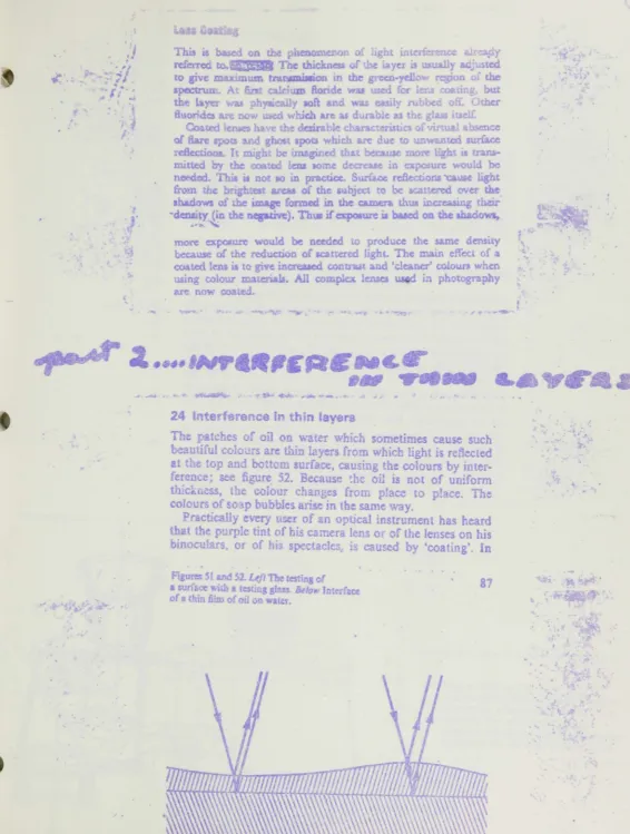
more expo;ure would be needed to prod\:cc the same density because
0;
the reductionof
scattered light. The m:Un effect of acoated len.
itto give
increaucd contrut and 'cleaner' coloun when
using colour materials. All complex lenus in photographyare no . coate.:!.
24
Interference in
th
n layers
The itches of oil on water which sometimes ceuse such
beautiiul cdo\.!rs are thin I yers from ;vhkb
light
is reButed
at 'he top and bottom surface, causing the colours
by
mter-ference; see figure
52.
Jiecause
~hcoil
is
not of uniform
thlc~n~s.
the
colour ch&.nges
f:
om place to place. The
colours of so p bubbles arise in the same
way.
p
cticaUy
every user of an optical instrument ha heard
that the purple tint of his camera lens or cf the lenses on his
[image:13.588.8.574.10.759.2]binoculars, or of his spe';taclcs is
caused
by ·coating'
.
In
Figura SllJ".d ~2.
uft
The testing of• SW't"&ce with It testing
sIl!!!.
&10 Intffl~or a t in film of oil ell Itir.
# - • • •
t A . !In
connection
with the previous
diac.wlSi08we
can
now
explain
how this works and why coatings are used,
We examine
tothis end what happens
if
there
is
-a
layer
A
(figure 53) with refractive index
11on a piece of glass
B.
whose
refractive
index is
n'. such that
ffis less
than
n', The
differ-ence in the paths of
the
reflected beams
is
2d,
where
d is
the
thickness of L'le layer. For the beam
a
which comes from air
(refractive index 1) on to
A,
there
is a jump in phase
equival-ent to a
Joss
of
balf
a wavelength, The reftcction at the
mterl'eoe
bctY.otll Aand
lJ
also camet! such a pbase
change,
and we must. therefore, take as the path difference between
Qand
b
just the distance
2d.
There
will, therefore,
be
an
extinction where
2J
equals a half wavelength; to be precise
the
half
of a
wavel~ngtbin
the:
medium
A.
The thicknesa is
t'hen one quarter wnve!ength. Such
lay~saxe
caned
quArter-lambda laYl.'lrs; quArter-lambda is the name
Gf
the Greek letter
l
which is always
wed
to denote the waveEengtb
or
light.
•
.
. 1 .. ;1t-
....
•
'"
..
#.
•
r
...
•
f
< • ~
;
f-r<
.
!>.~.,
.
~4:\v;..t-ft .... 41 iii 1,"" ~ "".
h'
\~
,<
\ ' \
l-1gun:s i9.20tuKl21. &kM
A <:iOSHeCtlon tbrou@,h
priam
~",owing the prism eomhlnatioo bl ligUle i 8. Top riglr' A.1l(<i.her ... y
o!
interchanging top arid boUom. l:irJItr..'ff rim ten
if •
.-IUch a lhit
(1 I 18, f'rl:cent of the
t<:sa'.
:r
0-y
I
'f.m
c
r~!w)" 0TIl
1l'"()ce~sf
f
g!.
'~tll ':U~'\..J ('nGrefiecli!'l&I.ycrlJl calkdcom/l".lht ,1 nn ges8cd
'IrU:1.In a pair !Jf bilo\;ular. COf c.tam1- 11, figur
)
heir
1 nten
glasf,/·air surf.,ces.
By reflect. ns a
It.:: iH~,about 40
pel
r:c
,t(If
the
fght
would
be
lost, smce
Qe
,;,a~-ir
mlerf~cc fOlect.s
4 to 6 per cent of the light.
Dy
coating
an
the surfaces, thi> 10.;5
is
reduc«l to 10 per
u-ntThere is ant,ther ac1vantase, at
~p.a...
tas
Il'fiporttUitIhf
light
reflected at the glass
sulfate
can, afl"'r subsequr.ot rdk:c
:ion~,go
in
the direction in
wh",,)
he
ina
"C is
lorn}d
t
ig'.H
~5{
The beQms
whieh
r~.achei"her
H·efilm of the (I\rnera,
ifthe
eye of the observer after never nurne
of .. e1J~dions
(
IJOi•
it
is
true, give rise to a sharp
J1'.1.' ~ebut
! Ileydo form'
~la1.eOWl'
the
din'lct
~age.They
reducllth
contrallt.t.r
1
the
unplcasantnea can take on quite set
101.1$aspects. The
r
IctUle
or
a landscape can for example
be
fl)gged by
the li~ht
)f _
e
sky
above the JandllCape. The great expanse ,hereof eft \ses
ilot or stray
light
to reAch the
film;
see figure 55, That is why
one must oot sllow tht sun to shme into the
lem.
The
fhotc-graph
in
figure .55 is made with an uncoated lens.
The coatmg enh.nces \ite
brillianct
of the
piClurtFrom
tbia
discusslOn
it
will
be
dear th~
t
it is im possible to
1;6/ VIi ;'ftthe
whole spectrum with one coating
If
the
illaycr
i\
u~t t(or green light with
J.
=
56()nm,
it
is obviously
llot dgh1k"
red lipt
with
A
a;no
om, or for violet
light wlth
A
4C{)
{OSf
,
Those
parts
of the speclfum arc, t.herefore. reOeded.
tll'ldthis
....
.
, ,..
-
-,.
'
~
..
),.
.
~""f~ • t
F
.~
see
the
pwplc bloom of
web
laych:
in
Nflected
li~;..R.c4
!
blue--vic:Jet together make purple.
Iy ha~..n.
more than one layer and
'Y
ChO<lrSlng ~teria!G carefully, it
is
poMible to
Obtaiilan impot'Wlt
IlctiOIl of rc&ctiQn o,'er the whoJe viJible 'ipt.(:trum..
~
few
word. about the
Makins
of
the:le layer!.
who~kness b only aoo,ut a thoU!Alodili of a mJlhmeier. For one
:f,
magnesium fluoride
is
used. If more than one layer is
fed,
one can for example nte
1lltemately
magnesium
ride
and
zinc sulphide.
hese
iubst.an~ are salts whicb melt ilnd evaporate at Itemperatures.
Tbey
are ptacul in
little ooats
of high
lng-point metal, in
tilvacuum chamher, which
is
pumped
n
to
one
bundred·millionths
nO-a) of lin atmo!ph<;u. In
chamber. suspended above the boats,
TCglau surfat::ea
: coated. The
ooats
are heated electrically. TIle saJt
meits
eV4porat-t-5.
The vapour hits the glus and
conden:,.~. Bysuring '.he reflection
of
hght
from one of
tht
glas:uurfaces
" ~
.
....
...'\< ••
.
,.
hi;II'C'l. 54 Bild 5,) &:1 ~'F;d.,e rd'kof.:tl>O"1; In
J
Ii
•
T
,
..,
"
. " AI
8.
ttl
'II
..
.
"
..
# . .
"'"
.
"
..
-2.1.5
THE PROPERTIES OF MANUfACl1JRED SINGLE, DOUBLE. AND TRIPLE LAYERANTIREFLECTION COATINGS.
2. .5.1
Si
Igie
lay
r.It
is
no exaggeration
to as!ert
that 95
%
of
theanti-l'eftectiun coatings m;}nufacturoo
around the
world are sUlg)e layers. Magne·
sium
iluoriJ~ (11 1=
1·38) e'Japorated
in high vacuo, is the material used almost
exdusi.dy
nowadays.
Theprocedure
lajd down
by
Smakulau
in
his patent
specification has been ent.irely successful
Magnesium fluoride is the only
material of
)0 Ifrefractive inde.t
flOmwhich mechanJl".ally robust and chemically
stable films can
ben.ade.
Cryolite
(Nt=
1·35) which m..5 very popular during the war
isnow
~ejectedbecause
it
is 'ater scluble; I.lUs
isunfo
Itnate because the refr .. ctive index,
k
';:f't.ha that of magnesium fluoride, leads
~oMore oesirable optical
pro-p ... rtie. tTzing maor1esiuTH
fl'~trkL,tre
amplitude r-clit10n of eql1ativ
f (24)cannot
hesahfko
[\ifmost opucul glasses. In Fig. 41
~he measured resUltsshnw that the r duction of
reft~tanceis fairly ood even for
gllmes
of low
refractive m.
ex. )
I J Iayer~of magnesium
ftuori,.1~were depo5ited on
glasIJ
wedge'l of ctificrel
t
rrfractiw :ndkes anJ care .va;; taken in measuring
0,11y
the
Ii
Jht reflected
iltthe
coatedsurface.
Tl1cerare
t1-e rr,easured intensit.y gl"cs the
r;flcc'ancp. of one surface.
~
Single layer antireflection coatings have the following advantages compared
wit muHi.layers:
gasse. of different refractive indkes can
becoa ed
simul-t
n ously with the s< me charge. Even a wrong
~hoiceof
theoptical thickness
re-!uces
the reflec'nnceexcept
for
'vavekngths
..iwhere the
opti~lf.l'iickness is
J12
).6' . . .
ana for these
therenee":!.1 ce
je same
~sfo
ntreat d
gfa~5.The reflectance is never reater (
f.
p.
28)
Ski'Icd worke·s manufact ring thin
film- .re at...le to
ho(\s~ th'rkn~5~c;so that he best resu
t
for each p oblem is
obtm 1
:i.
In the
pcrmal
Cilse
for ,isuat
oboeI'ati-n (b;noculars,
kro5cope,
spect les, etc)
t
chest
antircth-tion
property
isachie\'ed
by
choosing a
mmimum in the
green.
i.e. at
550.m. Then white light
jnciden~normally on
84
..
I
.""
.-....
,the treated surface
~sreflected
witl\
a purple to b!ue-viofet coJour. For a yellow.
colour of the film
tm
minunwn
iJ
at tho shorter WZlvelcngths, for a blue, hr-n
the minimum
is
at the longer (plate 3). The antireflection
properties
of the
blue films are not very
good
because the retlectance
in~more rapidJy in
the
short
than in
the
long
wavelength
range
(cr.
Fig. 41).
The manufacture of these blue films
is
preferred~due, no doubt, to the simpler
manufacturing procedure. Once
the reflectance colours of
the
film
are
blue
they
remain blue even for a displacement of the
refl.ectan~minimum of
::i:30
nm.Displacements
of
±
to
run are
easily
seen
for
films
ofa
purple
colour.
... .-.-..
~.-.-",-('11._._---7
•
--- "'.'62---
=U~_ · -.. - · _ ·-n,",,7-·
_._.-,
",·UI~---. ---
~----",-CAt---;.-•
+---~~~----~---_r__ 1110_
fl,. 41 The antlr.ft~:d~1I pto~ertlu
or
slft&le layoen deposltlt"d Qn substrates of dlfl'ercnt refractive Indices. It II the reflectance at one surface. (Carl Zeiss B-La.b.)A purple to blue-violet reflection colour of optics usually indicates antireflection
coatings of high quality.
Departure from these
film
thicknesses
may
be advisab!.c in special cases.
Glasses of high refractive index in pbotographic objectives are often strongly
absorbing in the shortwave region (yellow CY-Iloured glasses).
Bychoosing the
minimum of reflectance for an antireflection coating at 450 om, for example,
the refiection losses for this wavelength are very low and so the absoiptiotl of
the glass is compensated
by
using a yellow antireflection coating. This is of
, importance
~ncolour photography to maintain cc.llour balance. On the other
hand a red filter with an absorption edge at 600 urn and the minimum of
reflectance between 620 and 650 nm gives a very low reflectance for transmitted
red light. Plate 3 gives some impression of the change from yellow to blue of
the reflected light for an increase in the
filmthickness.
Drawing tangents at the minima of the R-curves in Fig.
4i
shows that these
paraHels to the i.-axis are nearer the
3Kisfor high refracting glasses and further
fer glasses
ot
lower refractive index. This distance from the axis gives a measure
of the residual reflected white light;
it
is high for Jow refracting glasses, and
8S
. r
.'
"
low.
fiJfhigh. Costro
glas~oC
low ref tractive index therc!ore exhibit Bttle
exaggeration of the colour while the ccnvcne is true for those of high rd'ractive
index. Therefore an estimation of tlte re(&'8ctive index of the truted
gtass
is
. possible from the saturation
of the
re&ctm coloufl.
2.1.5.2 DOllble
layer.
Only double
layers
with
a
single zero
of
reflectance
(c!.
p.
54)
are
discussed;
other
solutions
are
only practicable An exceptional
cases. Examination of
the theoretical
curve (Fig. 24 III) and
the
measured
R-CUfVes (Fig. 40)
shows
that the
reflectance
increases
rapidly near the zeros
T"
r-__
--
r /DO, .
10
"
,.
IJ
If
,.
IJ
Q 110
II
10
,
10----R,T hettFiltIr
,
- t t 7 ~I'ilm'"
7
,
JD5
,f ZO
J
R I
. , / m
0 .."... .
~
e~ially
at shorter wavelengtlu. Wh.ite tight transmitted through a compli
-cated optical system
~uchas a binocular treated
with
a double layer with zero
of
reflectance
at 550 rim emerges yenow-green
coloured. In
the
neighbourhood
of the zero of reflectance the adwntage gained
by
using a double
layer
it
a1W~lYSlost du¢ to
l-Jgh
reflection
at
the
edge
if
a wide Sipectral region is
used.
Consider~able advantages accrue
by
usina a relatively narrow spedlal
I'C'po.
Fig. 42
shows the advantage of using double layer
antireflectioB
coatings as
pho~ootilters. The h.igh. refieetanr.e, 14%. for.t
=
400 nm is not a disturbing influence
when thc red filter is
used.
Ught of this wavelength
is
absorbed
in the
fil
t
er
.
Provided
that the
filter
is
always used then lens surfaces of
the
objective oo
u
ld
86
.
~.
.~
..
...
.\I
1,--:II
..
~
.t
'.
..
, )
•
~
..
~:'
II
.
,-~
...
t . '
,"
be
treated
with
similar
double
layers.
Optical
obsenratrojlS
are v-:ry often carried
out in green
light
which is
less
fatiguing to the eye.
In
this case,
the
double
layer offers a
considerable reduction
in
the
reflectance
compared with the single
layer.
,
In
addition to
the
physical
reasons which
militate
against the general
applica-tion of double I
yers,
there are important commercial reasons. Double layer
antireflection
coatings
are considerably more expensive
than
the single even
when
it
is
technically
pOSli'ble
to
evaporate the additional
highly
refracting
layer with
ease.
Different
film
thicknesses
are
required
for glasses of different refractive
indices so that different glasses cannot be treated !;imultaneously.
Greater care is rcquirtd
in
controlling the film
thickness
than
for
single
layers. For the single layer an error in the thickness ouly means
that
the
J
1
"'" 50) 5!D 6a)
r:I,. 43 Antireflection by a triple lay.r o:~ 3 Din~le .urface It .. .,. 1·52. (Carl Zel B.·lab.)
minimum (or zero of
reflectance
obtained
by
sathfying the ampJitude condition)
is
shifted
to another wavelength.
By
contrast an error
in
the
film
thickness of
a double layer implies that
no
zero of refiectanc"e occurs. This can be disastrous
if
an increase in reftectanre is produced instead (cr. Fig: 42), i.e.
if
the wrong
thickness is chosen
More disastrous,
however, is the fact
that the
reflectance
of
the unt:oatcd
glass may
be
enhanced jnstead of reduced
(cr. Fig. 42).
2.1.5.3 Triple
layer.
It
is possible using a triple Jayer to reduce
the
reflectance
over a wide spectral
range;
~hisis not, of course, possible
with
either the single
or
couble
layer. Measurements of a three-layer antireflection coating are
displayed in Fig. 43; this was made in the author"s own laboratory. The
em!
and manufacturing problems are even greater
than
for
th~double
lay.r
and
so
triple-layer films are
only
used when
they
are
fully
justified.
,
1 riple layt:r antireflection coatings have
improved
the p
ition for
micro-scopes
0"the.
reflect~light
type
and progress
h.u
been made in special cases.
Thr(';c flJndamental
difficuil,ies
rn)s~rati!lthe search for a
genemU
solution to the
problem:
(l) For gW&es of higher
refractive
index
it
is
ne~ssaryto
increa~ethe
refrac-tive
inde~of
the
i./2-1I1yerif the
eS1dual
reflecunce for
such
grasses
h
to
be
,
kept as low as that shown in the example for BK7 lass
(fig.
43).
rn
practi~.one is
fortunate
to find
even
one highly refracting material satIsfying
the.require
mcnts for such a film. If the refractive index. of the
1./2 film is unaltered while
the refractive inde)( of the substrate is increased then the ba. dwidth of the
region of low
reflcct~!lceis educed. The residual reflectance for a triple layer
i-
not mu<'ll lower than for
single
bier
if
the refracllvt; index of the glass is
greuter than 1·65.
(2) AU'im
ent of
the desired optical characteristics
of
the triole layer is
dep
n(~t:nton laying
d~)wnfilm') of accurate
thidmess.
or
surface~W!
h
~teepcur\', lure
trJs latter is
very dlffiwlt
t.)'chit;ve,
Nc ,,·rthelcss IT)ethDds
are
a atlah1e for vacu' m coating such
f,urf'l~eand even hem' pheres
(",1n b~coated
WIth
a
h ..
:cr of c .. mtant thickness. Dut lenses used in
micl
oscope-objeclives arc
'cry
tiflY so
t iat e
laportziltion of a film of uniform thickness
becomes very
d'ffit,ult.
(3) No eu'table m ter.l.ai with ref-tic ive index in the ra
ge
1 65
tl)1,8 which
can e us
d h
the
rn~nufactm-eof
t!'pIe J<'ycrs are
kMown.
Films of thi4;.
intermed' .. te refracfve jndeK
(n3
in, tne th~oreti':31trentm"llt)
nlIl~t bl!produced
by
a n ixture of high and
11
wrefra' ing natcrials or
by
equivaient layers
(GejJcken
60).The
fllm design must be
:hang d for
gla5~e~('If
difr~r~ntrefractive
ind .. · and
,,0:imul.aheous evaporation of triple
IRyel"s
(\i.di!fcrent glasses
is
impo,;
ihle
(i.e. as for the d' ble lay<:r).
Clearly then triple
laJer~shouid
Dnty
be used
wher
~the most
stringent
antireflection properties ure requ_ired. In these cases a change in reflectance
rom
0-1
%
to
·01;~is of great imF
vTarlee, Thcro::fore
the
optical
thic1(nes~esof the layer$ mu.:t be monitored
very
clactly .
,
.
~
~
,
.,..
2.4.4,6 The production of arr()w
lUld pa s filters.
First of all a
gre
t1
of equipment and pea tical
still are needed. The
~pecificatil,)nfor
Amaxmust be
s ,tisfied to 2-5 nm and the specified half-width and b.'\ckground carer
1y
matched.
It
is
very
important that a uniform film th.ickness is maintained over
the
whole filter surface; this ensures constant.it
maxfrom point to point O\e
rthe
surface area. This last requirement
dearly
demands
highly
sophisticated ins'
mentation to att..in the degree of control impHed. From experience
it
is Imown
tl
3t
a filter with steep edges and low b ckground
is
preferable to one with
onl) a sn.ali half-width. Sped liled firms such as Bal:r,ers in Li ht mtr.in •
I'Schott
&Gen in
Mail Z have
~oJ""cdthis problem satisfactorily.
FiZ.
78 s1
s
the
transmisslOn characteristics of the fo r most im ortnnt filter types
Dl'1U-facturcd
by
Schott. The filter properties may be
betler
appr~c'&ledby
tabul.
~tion; Li.e following are quoted from the Schott catalogue.
Sp«lral
171,0'.')'(4 T. HW dW/HW hW/HW tW/HW
rt-glon nm % nm
390-800 Line filte!'l
.
30 10 1-7 3 9390-800 Line dOlJblc filten 10 10 !oS 2 H
390-800 B;mc! illterl
.
ZO" l-1 3 9390-800 &nd d')ublc: mtCfl 30 16 I'S Z H
400-700 ColQur filters 31) 10 3 til
800-1,000 I..ille filters 30
is
3 10where
T
max=
rnaximwn transmittance, HW
=
half-widtll, dW
=
tenth-width
hW
=
hundredth~width.tW
=-
thousar:dth-width.
It
i"
seen
that
only
th
"
c{}lour filter and the line fitter for 800-1,000 nm are single Fabry-Perot
tpc
(the last two rows). The Fabry- erot
rut
r usually has a value of 3 for the
ratio dW: HW. Thls suggests that the line filter gh-eil in the first row must
a more complicated systehl to acbip:ve the Iatio 1·1.
Changing the
thicknes~of
~he spa~rlayer shifts the position
SJf
Arnu;t+'
sugl;;ests a method of using a
"W~gedI yer as
IIspacer so that
he position
.Am "':
may be
variedcon
lrJuousJ~.~(Gr ded tipe:trum filtetS.)
2.4.4.1 P
rrOl~band pa.'i$
pllers /0
the
J.lt
A special ad
rage of th
interference filters is
tpn:,.sibility ohhi ting tb band
pac;
to ..ny
wave
t'
.', ,
'0
r:ot.J Nomo.Y {I;zfId fjfUr 60
FI,. " Interferen« fllt&rs by Schott ar:d Gen, Halnx.
required
by
a change of the
film
thickness. The
many
possible ib:oretical
solutions are oft n limited
by
the few suitable materials. It has been shown,
for instance, that silver layers can
only
be
used in narrow band filter in the
range
350 to 2,500 nm. Aluminium layers
may
be
usea
in
V.V. filters to 200 run.
Highly refractive materials such as zinc sulphide or some metal oxides are
sa.lsfactory in the visible bit &bs')fbL,S in the U.V. Lead fluoride and
ma.g~nesi m fluoride respectively the high
and
low efractil'g materials serve as a
hlghly re ectjng multilayer system to the ab· ptJon edge of leaa fluoride at
23
nm;
but the reflection bandwidth is
s.
aU '>ecause the difference betv'cen
the refractive indices of the two media h small.
i
tlle
:l.R
region, how'
vcr,
the
conditio.
~for prod lei 19 fillers
by
U!.ing
alternate high il1dex
-low index i,)lms are even bett
~rhan in the vlsibJe.
M~teriaissuch
antimony S1:
ipnid ,
silicon,
and
germanh..m
hich absorb
in
the visible,
re
uon-absorb:ng
in
the 1
R.
over a
wide
Jang of
~velengthand
moreover
have high
refn~... tivf' Indices (germanium
n
=:. •fenil
1123·5).
Hass
and
Tuner'7
produced fficient' er<> u.ing such rna.
'rus
~edwith
a
Gw
rerr·C'ting st.tbtanc"", e.g. cryolite
(Ii
=
1·3).
m
a, ..
,e
d ct..r'.., ances
only
a few
B y
.s l"e
requ'red
to
I1lh:eve
a
high
reflect nce
nd therefore I
r
"reflection
band~idths."
'\ '
.. '"\Ji. I
: Dr.
This article is one of
(1serf
ffjMd
taexplain
the
prOWIII ~for
'"
various
types of
optical
coo;;np$.
A
techniqv(il
to
produce
anti.,.~tioncoal-ing
y.ith
f':ingle
layer
magnesium
fluoride is
0xplo;n'ld.
Tho d<wning
01
sub-;g
d
scribed
tlnd
tha procedUf to bt;; followed
;~outlined.
u strate
ffxtUlftS
and
methods
of
substroto
mounting
ora
SU9f1ss?ed.
VOCtiumpressures
and
wbs
role
l~mperot'Jr&!for hard bctked
coc.fings
and
a
glow
discharge
n'HlIh«llor cold coating! are pteJMtcd.
TIlE EVAPORATION OF MAGNESIUM
FLUO-RIDE
has ~ used for many years forba:rie
anti~re.fiection coating
inoptics, 11le effectiveness of
thUl
type
of coating has been thoroughly
explored
and
ovahllatoo.
The pu~:;e of this pSp&l',iJ not ~
cf
-tie
layer magneg-lumfiuorlde
61mJ
or tmti-reAective
eHec-tiVMe5S, bUI;
rat.her a
method
of
prodlllcloga rupenor .
quality
filmeconc.mically
and
eHicrently.
'The method and P~Uf(!ll
which
follow
havebeen
t.horougiuy proven and used quite :ru~ny for many years and am applicable for laboratoryas
wenas PI";)d'lction.
Thu major piece
'Of
equipmentrequired
for!ill
op-tical coatlnw> is a vacuum ooating machme. The
~of
this
is determinedby
the lpedBc nood. Themao
, chine discussed is a standard
1~'g1ass bell jill"
typrt~with
a
6"oU dilfusjon pump, a 15
clro
mechanical
pump, n 1ilament power.=:d
by
a
2 ICV A
t:r..msfOlmef
, _ wired to sYjpply 20 'Jolt!, a substmte heater and a
gifJW dJ.schar~epower suW}y.
lba
Ci~jftll~n,elf
SMDlttab)sClean subsb1i;tes are
& prerequintefur
!lmO:t1:Mtw
roating.
'This
stage
has
probably more varlmtkms
llian
My
other part
06
the coating protWll.
HO'JVW~ll'p (!;Xu• ~e'Ilce
bar-
provenihGt
therE1
is no m~burt
cut
which
a!'1l ~utilU..ed
to proaUOfJde8m,d
r-em:lbl.
ooatOO are th'I'JD robbed
with
a calciuo::
(~~prognated
pad The substratl!) is.rinsed
4g&in . "Citrunning tap
water. The surfaCJe$ ilia
ha,r
mbbed 5md
ri.nsed
now wet m'eruy.TheIl tho!ro.
strntis
placed
in Iiplast!c
pan
or
t.mlk
of
W'IU"m ~irtct. {tel·lining
th",
bottom vJith diaper cloth.
TIt-_
!'m'.Il.8atl-dum
carbonate
I'ICfUbbin&
isdv
to
t~eJ'etnam
ingiSu:bstra~
that are to be
oo.!!t~d.One at a time
tM
aubsbares
are umoved . ilddipped into a
tray fit panoontaming
Ed: ~mulBifyfnidetergent.
Certain h()USC'..huld liquid
(i. ~rgent3bave
ruso
proved
rucoem11l.
However.
if they
:are used.
tb.e
cleaned
substrates must
becoated
imm~teJy ~cleaning.
which
:isnot
oocessarywith
UI! ~fJ'f
.m
eDlulsifymg
detergent.Next,
th~substrates are dried thorO!.l
1y1fu
ctOOll c~loili. At thispomt,
a bl'f"..ath P" ~mt~: ~"'l 1/be
done
tosee
if
ilie
cheese-doth
lw;rodu
-u
w,;'Wipe
marks. nus
Deednot be
dm e 0IMfS.
~bstrnte.
unless
It.random sampling
IlOWS • 'W}Each
rub~lhate i!lplaet.'<1
ina
trayIi ,.
-;cl'l
~tarmsll
free
pa.per. They IU'~ 'Pla~ 'Witb13
S',~bf, vJi:lted
down.
Tiley
are now ready
X' ~ inthe
UK1:U.fe.trLe
iniporianCe
of properc1_ mng
the
str?ngiy cmpba.w.ed, The
~1Jl»tm.temust
'b8
\'l,>lib
the ebaJlc: paste
with:orne deT"
fIf
The final pin should
lso
h~ notit
and 'MthQut fear of :lam,
gf-Dgth
17 J 1-,Mrmy
S".lbmates: of oretlc"e quali an
itlnis'h bmve been cleaned
tins;
way
Wi!.} 0,'The fo'ik'iWtng method
[If
clOODJng
hu
~highly
satbfactnry for
gltmor quartz
S'u'b!ltrateiJ,
not
plmst!c
(61:' optically polished metal. Celchnn
omrOO:ne.b:3
pre.cipitate fi8 mixed wtth
distilled
water 0 fonn a thlck'..--/
~l\te. A w~dof cottoml1fJ4')l
OfSe"/<eNl gaU2'.e
p&(lsmm
fcnked
inUte p&ste.
Tbi3
:ri.1b~tmte ,~ W0tby
holding
it
under 'Warm, running 1'1!!p
~·~_ter.Jill
fm.li1'1tcm
~o'be
scratches developing. h~'evet'
.
'lCrubbing pad:;
aoo
wlpwf4
cloths
~,
whpn O')ntZlmioob>d. for
Lili g~U,0«;.,.,.
du.ung the demm
proce.<JS.
Sho
ttl
t u:: l seii ,d clr.
,,~ h. qfl1un II nil "'. 01 . m t fame r
tn
t
tloo
I' Jtl" "raron of tho .;ubs, tcs beforethey
enter thebela
fchambc t;!" i III nl'tnnt to tho uccut;flJ! ooatmg" M
tho
r..unl (;
'n\,~offltilln.item'! hnve
beetl nmdoto
e
f
Ifm,:n~ rm.i\.;c{h~.1 ow .
,1',oone bils
proven lat;
cons~knt.y
and
th~l"(hlU.hly de~MR~le.
Substrate Finhlre
The
lZC('If
th'l g!~W Uto
00tOO
d
temdnes
'hethe!
o l:e C hundreds of the ico$e$ 1M) he coat
-d
attho
iam trrne. Pro :.:r firturitlg
enabte:t
the coatingof
.n
many Ic •. :,cs a. can be
fit
into n chamber. Proper fi.xtur~i11g n1~ p.~ l:'~ co
101 of
film
thlclmes
50that all the
zubsti"1':t
l'!U"X)nteo
tothe proper l'eC1uirements.
For large
tIt!
ntltk~ of le!is~s or :.. ... dows t.§the
same w'"'m
to ..r,
f! rill:";:.:1e
fixtJ.!'$W
proven
most
u .. efuL. The
mal.,'Sol
b.-;st %J'~ ~ ."ronsk!ertng oojf'..,
machine
h~p\
W ' ,I'!nd the
flbm~ to ~i.!.ru:t1nd \-aCouum and he.
i.TyI"t'<
,l~T6or
~"f5Ah.u:afu·.un.
Etlan
rmgs re
cn~fmm
t ~ n..St~ill!illY!
arc
w~(he!illlC) together to form a
domo
sh~~ btur~ 113 ,.. hown ill Figwe 1.
=--__ =-______ rr _ _
~
_ _ _ _ _ _ _ _ _ _ _ _ _ _ _ _ _ _ _ _ _In
rn 18" bell jar, the
~fro
th
source
(magnenum fluoride) to the substrate
Ihould.
he 'i:least I!!" or m'lre, With
this diWmee,
tho radiwm
the dome futture
is notcriti:-al The
81.emge dcme
awbe (II) truc~
,d
QS shown inFigth"C _
~~-
.. / - - - - ISP."-
i
TABllll
.0. OF RING
O.D. OF
suas
RAT
-.---
.
.-....-~ "0.008"
0.012"
0.015"
0.018"
0.022"
Q.02Sf'
~l'ierth8n" ~I
:. II
"
,.
JI "
" H
Up
to ~"
%"
to1
fI1
%"
t.J
J'
3"
t() ~:4'4~"
to 7l¥'
1W'aM
'p- . , - = _ _ __________ ~3...
..."
The
esting ledge of
the riag
should be
desi~ so th~t Il. practical mulmum oreaof
~ sub~t0W
coated. 'The procedure fulloWE-d
ispresented
below-see Table
So
TAklLE 2
WIDTH OF LEDGE
'hmm
~mm
Imm
llkmm
2mm
2;.2
mm
3mm
3lhmm
0.0. OF SU8SrRAn£
Up to~" ~~" to 1~"
1
%~'to
~'it
P21h"
tu
3'~"3; ..
~!1to
:~"a"
5\'2"
tIl --~ , / '7V2"
to
8
'i'
8¥2"
ald
up .f'\
~,
....
., ... _ _
...
= ...
w_ ... ""' _ _ _ _ o;,. . . . q;..,.._~A
typical 'Cl'OS! 4eCticmof
QBxture
ring iswown-Se6 FiguM3.
Provisio should be maC:~ on the romp!&" ed mt; for ~ nng to hold
tht;
test
1 n5. This k. t ell:t ringbonld
be
permanent prut of the dome. • ~, ~tionis 001t at the front edge of th(! Oxtu,-e, as s'ho.va in
the
photograph of Figure
1.
Also,
pro 'isions TIlT ;nountingthe c me in the bell jar must be made.
t
wOd!d
be mostdesirabl
to have the ~est lensmade o! the same index as th,
ub~trateto
£.
C>:':'le .. '
Th~ i
impractical; : erefor •
alltest
1 e.'tusOO
.bou1dbe
of one indfU. The t:-cimici"n must a himselfwith
the shghtvane
'ons in the re~r (' , ofthe
diff-e~dcooted mdices. Thl ,
h" tt
whicl.
helps manito theth'"
es:; of th ...r
devapontticn crul be coated to a tUclmP'i v ~cl:J
will.
dil'e«ly
correspond to tha f.h: knE'.s.~ of ,.hc h 1 on~b..'1l'4'''3
..
'Th~ ~..
rr'~d
tc ... t Im~ ;J1, .. d andfrn )
dto 'I,s
~ towr-ric
\'l.ith, ~t
'ntgWs
of index i 64~ )Wltn Ii ~ N~ of 3.329" and a concave radius
f
I
II
,
~
I '
I
I
r
1.623.". U' ct r ci ti", kt;- , fill
1.£5 •
Tho im1Gm
~M. et in
th
filttt!re
50 tlwtthe
vex
dius
JI.qeootcd,
C
I\tor ust.'<l test
ICJlso:!may
be
ma;0!I'Ict.:
ro
~...
~thf\
coolin ~aoo
used
ngJlin. .~ervery
pr~(&jtyyw ~E mating arturo primwity for mW1 qwmtiU~
ok
u
it:.ltC5 (stht ndjU!table
~as
shO"ND inFig:uftl
~.,'tift
:&xtttrc
C.llDQ(oommoone mEbstm""1es with'
df ..
I!\mdm up to
8""
or
3"
x
10"
~l~yshared.
Tho rob·,trnte.s in
thi&
CIlSe a.re not intM
WIN! arc pI ne ,~ ti,e te!lt len:: intl,e
doole typefixture.
Withthis
typ
(Of
j;& t.h~ s\1b!'ittn (1" \"0" 0 ,to the :Dureem:l. r~! and
therdill'a will
be 6lmcd
~oonertb..r.
~notest Jen , Ths tNilinician mtm
GCOOnt wr
·this
diffu..
elieo
h .
sllowing
the
test len
to
bf!
coot
to llgh~or}!):r or thinner 61 n
thic~~. With ~ngi~laym'rums
, ,. of m
~erlum fluoride,
l!lJ"eUoMh15
cleg..~of
monJ..
ring
GCCUl'a~1am r.n!rl.ly
be
acbie'lt'd
11.tm ..
prottke.
-
-
"'"'
-7he ffemctive oolnr changes
whichthe
t~tlens
will gc through during evaporation are light yellow,
straw,
p~.pink-purpl • blue.
llgh~blue and
white.The
pml,t-pmp].3
~ would be considered" wave forth" roWdJ.a of the
_t~bl9spe<.iTtnn
(&250 f~). Pmkwnuld
~j ~~ ',.~for
500 A
area
tmd
blue
W2.'-~for
th
82$ A
exes, 1m WIt\'e for5000 A. 1M
~ wavcl ~~ oro(;t' ~ j~ the
deired
tbicbe
for
an~..
.r~ CM~~(''1
Sugk; hlyer
of
m:~i:r'-"&~um
fluurlcl
;~w brc»d
int?J
•
~dect
that
moot M1lcpmts ;roq~lng Gn ~
to
b
coated merely alt3te fue nqui~1 .-;.~ ~ W<lV6. Tb~
_//rneans
that the m.abraaio
J\'j,~p !rtmw~
p.:,ru;
pinl·.pwple or blue
and'
't.J.ll
~~ tho .n:q. y~tJof
t~~~ bl~1epMt.It is dv
Ie
or t t clmlCl wh i L'l Wltr""i4Hiru
with
the
&active cnlorg
~lied
with Vi. • 0",rUm
t~t
'0 . t\ ~ooatiilg
to
00-s..,
tlus
ft')CLAI
c
test
rem:
h
ISleft
·tlw
Lgb
b no
color
and is oomg
Wl bitt:.md
the eYapA>Ti1": £.s continuedth£
color sequenoo v:ill !cpd'ttitscli,
be-coming
y~w,
stro ... I pink. puk
purple.bI"
f •blue, green-whHe.
However,
tills is in ilie" NV.'Ifiwc--orad order- Jmll'.imum.
1£
the evap<:mo n
~to
.::on
tInule.
theseqt enre
wouldagain
beubi . • ...
t.i'1UItime in the 5/4 wave third order rna: . •
lID.Tht!
tt:<:hllici.'ffi. S •uld
CODCentra"o .'~ffo11'=
inthe
oo1or
cbange!i
of
the fi."3t
croat
rna :mu '\.,
On~M
comes
qti1tt1
fnmU!ar whh
t~ ~ .. ~ ~fj. t.iand quite
Gff~tlve m.onitt}rJ)~ 7 -.'beEJl
~Ci:UCcd
linGle
lay~l'mapesium
fluoride
filin.
'.
.
~
0-~
.
t:~.
"
¥UP'"-'
tio~
on
1vl
gnes'um
E oride pov.dfJl'
of
opn
Lained
and""'den not
inuse :;
iou1d
be !!.sk~'l.tor t~ with
de
~ic~ll'lt."When
p."p~D\l::liU ,
R
I lid ~ for ~\'ap{)mt!{m, " '->!rudble wi h n rim <