Dissertation submitted to
THE TAMILNADU Dr. M.G.R. MEDICAL UNIVERSITY
In partial fulfillment for the Degree of
MASTER OF DENTAL SURGERY
BRANCH III
people and it is a pleasure now that I have the opportunity to express my gratitude
to all of them.
I am greatly indebted to Dr. M. VEERABAHU
,
Professor and Head of the Department, Oral and Maxillofacial surgery, Ragas Dental College andHospital, Chennai, for his exceptional guidance, tremendous encouragement,
time to time motivation, well timed suggestions and heartfelt support throughout
my postgraduate programme which has never failed to drive the best out of me. I
would like to profoundly thank him for giving an ultimate sculpt to this study.
I wish to express my gratitude to Dr. S. RAMACHANDRAN, Principal, Ragas Dental College and Hospital, Chennai, for his timely help and
encouragement throughout my post graduate course. I also thank him for
permitting me to make use of amenities in the institution.
I thank my Guide Dr. B. VIKRAMAN, Professor, Head of the Virtual Lab, CT data conversion and simulation, Physical model simulation, Department
of Oral and Maxillofacial Surgery, Ragas Dental College and Hospital, Chennai,
from the bottom of my heart for the inestimable guidance, precious advices,
generous support, constructive discussions. Without his presence and supervision,
I wish to express my gratitude to Dr. MALINI JAYARAJ, Professor, for her untiring help, back up and generous support throughout my post graduate
course.
I would like to immensely thank Dr. J. A. NATHAN, Professor, for his concern, guidance, constant support and encouragement throughout my study for
which I am very much obliged.
I owe enormous debt of gratitude to Dr. RADHIKA KRISHNAN, Anesthesiologist for her valuable guidance and support throughout my course.
Her loving and caring nature has lightened the burden of many hardships.
I thank Dr. SHANKAR, Reader, who has helped, guided, taught and supported me not only as a teacher, but as an elder brotherly figure.
I thank to Dr. MUTHUMANI, for his valuable support and guidance and his scholarly ideas and comments.
I would also like to thank Dr. SEEMA, for her valuable suggestions and guidance.
My sincere thanks to Dr. ANUSHA for her support throughout my study.
I thank to Mr. PREM ARULLA (ManagingDirector ofPERSEPTRON
It would not be justifiable on my part if I do not acknowledge the help of
my fellow colleagues, Dr. Manikandan, Dr.Abhishek Johnson, Dr. Brian, Dr.Saravanan, and Dr. Vimal for their constructive criticism and continued support throughout my post graduate course.
I would like to extend my thanks to my seniors and juniors for the help.
I thank the Paramedical and Non-Teaching Staff for their co-operation and help.
I thank to all my Patients who participated in this study and came for regular follow-up.
Last but not the least, even though words wouldn’t do much justice, I
would like to specially thank my parents and other family members for their
blessings, love, and best wishes.
S.No TITLE
NO.
1. INTRODUCTION 1
2. AIMS AND OBJECTIVES 3
3. REVIEW OF LITERATURE 4
4. MATERIALS AND METHODS 22
7. RESULTS 31
8. DISCUSSION 49
9. SUMMARY AND CONCLUSION 65
1.
PATIENT 1 PRE-SURGICAL VALUES ( LENGTH OF
VECTORS PROJECTED FROM TRUE VERTCAL LINE TO
EACH LANDMARKS)
2. PATIENT 1 POST SURGICAL VALUES
3.
SOFT TISSUE CHANGES OF PATIENT 1SIX MONTHS
AFTER SURGEY
4.
PATIENT 1 PRE SURGICAL VALUES (LENGTH OF
VECTORS PROJECTED FROM TRUE VERTICAL PLANE
TO EACH LANDMARKS)
5. PATIENT 1 POST SURGICAL VALUES
6.
SOFT TISSUE CHANGES OF PATIENT 1 SIX MONTHS
AFTER SURGERY
7.
PATIENT 2 PRE SURGICAL VALUES (LENGTH OF
VECTORS PROJECTED FROM TRUE VERTICAL TO
EACH LANDMARKS).
8. PATIENT 2 POST SURGICAL VALUES
9.
SOFT TISSUE CHANGES OF PATIENT 2 SIX MONTHS
11. PATIENT 2 POST SURGICAL VALUES
12.
SOFT TISSUE CHANGES OF PATIENT 2 SIX MONTHS
AFTER SURGERY.
13.
PATIENT 3 PRE SURGICAL VALUES (LENGTH OF
VECTORS PROJECTED FROM TRUE VERTICAL LINE TO
EACH LANDMARKS).
14. PATIENT 3 POST SURGICAL VALUES
15.
SOFT TISSUE CHANGES OF PATIENT 3 SIX MONTHS
AFTER SURGERY.
16.
PATIENT 3 PRE SURGICAL VALUES (LENGTH OF
VECTORS PROJECTED FROM TRUE VERTICAL PLANE
TO EACH LANDMARK).
17. PATIENT 3 POST SURGICAL VALUES
18.
SOFT TISSUE CHANGES SIX MONTHS AFTER
S.NO TITLE
1. LATERAL CEPHALOGRAM WITH STAINLESS STEEL
BALL LANDMARK
2. LATERAL CEPHALOGRAM WITH TRACING AND
MEASUREMENTS
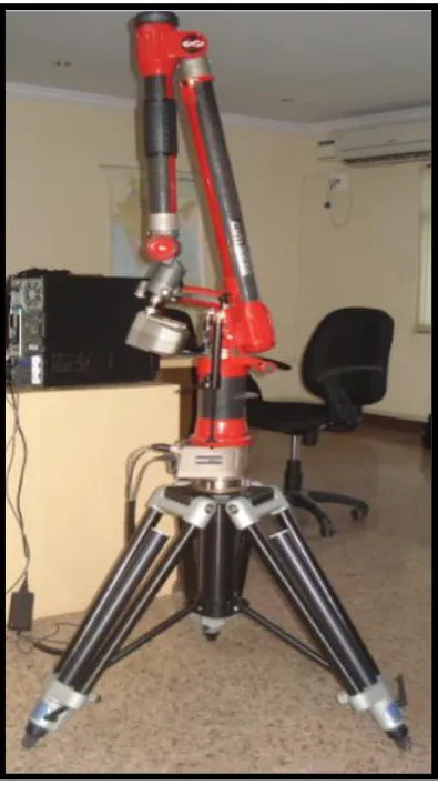
3. PERSEPTRON 2 M LASER SCANNER
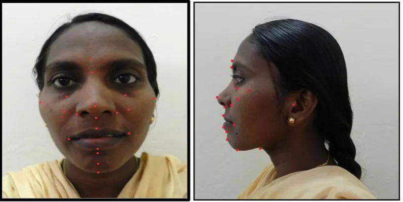
4. LANDMARKS ON PATIENT’S FACE
5.
SCANNED PATIENT FACE WITH LANDMARKS
6. FRANKFORT HORISONTAL PLANE AND TRUE
VERTICAL PLANE CREATED
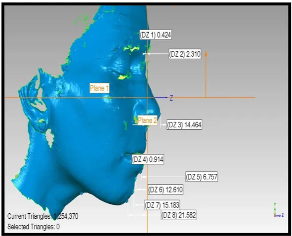
7. PLANE CREATION AND VECTOR PROJECTION FOR
MEASUREMENTS
8.
PATIENT 1. PRE SURGICAL LATERAL CEPHALOGRAM -
MEASUREMENTS
9. PATIENT 1 POST SURGICAL LATERAL CEPHALOGRAM -
MEASURMENTS
10. PATIENT 1 PRESURGICAL SCANNED IMAGES –
FRONTAL VIEW
11. RIGHT LATERAL VIEW
15. LEFT LATERAL VIEW
16. PATIENT 2 PRE SURGICAL LATERAL CEPHALOGRAM
MEASUREMENTS
17. PATIENT 2 POST SURGICAL LATERAL CEPHALOGRAM -
MEASUREMENT
18. PATIENT 2 ( PRE SURGICAL LASER SCAN)
FRONTAL VIEW
19. RIGHT LATERAL VIEW
20. LEFT LATERAL VIEW
21. PATIENT 2 (POST SURGICAL SCAN)
FRONTAL VIEW
22. RIGHT LATERAL VIEW
23. LEFT LATERAL VIEW
24. PATIENT 3 PRESURGICAL LATERAL CEPHALOGRAM
MEASUREMENTS
25. PATIENT 3 POST SURGICAL LATERAL CEPHALOGRAM
MEASUREMENTS
26. PATIENT 3 (PRE SURGICAL SCAN) FRONTAL VIEW
27. RIGHT LATERAL VIEW
orthognathic surgery. Each technology comes with its own limitations, advantages, and costs.
We compared 2D and 3D Soft tissue evaluation techniques.
Aim: The purpose of this study is to evaluate the limitations, advantages and cost factor of two different techniques for evaluation of soft tissue changes after orthognathic surgery.
Methods: Pre surgical lateral cephalogram and laser soft tissue scan taken. Postsurgical cephalogram and laser scan taken 6 months after orthognathic surgery. Soft issue evaluation
was done using Arnett and Bergman analysis. Both presurgical and postsurgical values
compared to asses soft tissue changes. 2D and 3D soft tissue evaluation techniques evaluated
to asses advantages and disadvantage of each technique.
Result: Laser soft tissue scanner is an effective, more accurate, and convenient tool for soft tissue change evaluation.
Conclusion: Advanced 3D laser scanner gives exact 3D information of a 3D object. Technique is easy, and needs less processing time. All measuring tools are incorporated in
data reading software. Measurements show accuracy in micron level. Lateral cephalogram is
cost effective, but it represents 2D aspect of a 3D object. Examiner level error in
measurement is common in 2D soft tissue evaluation technique.
1
INTRODUCTION
Correction of facial deformities with orthognathic surgery is the solution
for many people who are not happy with their facial appearance. Osteotomies
performed on facial bones to correct deformities, but patients perceives the
results on their final soft tissue position.
Many studies have reported various results in measuring facial soft
tissue changes after orthognathic surgery. Lateral cephalograph is a
conventional tool used to evaluate profile changes in soft tissue, but it is not
the apt imaging technique for soft tissue assessment.
The soft tissues may not be observed clearly due to low resolution of
the radiographic image and superimposition of structures on soft tissues,
resulting in landmark identification errors. Most important problem is, it can’t
show the 3-dimensional (3D) changes of a 3D object, hence, the search for a
good 3D imaging tool for pre and post-operative soft tissue evaluation
continues.
Conventional facial moulage, Optical systems like Stereo
photogrammetry, Telecentric photogrammetry, Moire topography, and 3D
computed tomography scans are common techniques for imaging facial soft
tissue changes. The laser surface scanning system was introduced by Linney
in the Department of Medical Physics at University College London. Laser
light sources were used to record the facial soft tissue image in 3D to evaluate
2
to use, accurate, minimally invasive, cost-effective, repeatable, has high
resolution, carries most of the advantages of a 3D imaging tool. Many
different technologies can be used to build these 3D scanning devices; each
technology comes with its own limitations, advantages, and costs. We have
used PERCEPTRON 2M LASER SCANNING DEVICE to evaluate pre
surgical and post surgical soft tissue changes in 5 patients under went
3
AIMS AND OBJECTIVES
The purpose of this study is to evaluate the limitations,
advantages and cost factor of two different techniques for evaluation of soft
4
REVIEW OF LITERATURE
Spadafora A et al (1946)76 Used poly ethylene implants for malar augmentation.
Hinderer U et al (1971)31 Surgeons previously used unilateral bone grafts or silicone implants to correct facial asymmetries, bilateral malar
augmentation to improve facial proportions was first described.
Freihofer HP (1977)21 It is important that patient must be informed about the potential side effects of orthognathic surgery, inform about the need
for future nasal surgery. Patient satisfaction ultimately be derived from the
final positions of soft tissues, rather than the skeletal movement.
Radney LJ et al (1981)63 Found that soft-tissue chin landmarks follow horizontal bony movements in 1:1 ratio after setbacks, advancements, and
autorotation.
Collins PC et al (1982)16 It is accepted that the alar base of nose experiences some degree of widening after maxillary impactions and
advancements. First describe alar widening after LeFort I osteotomy, they
suggested alar base cinch to prevent this undesirable side effect.
Quast DC et al (1983)62 Several soft tissue lip, chin landmarks are found to move posteriorly around 1.9 to 2.5 mm between average time points
5
landmarks move posteriorly during same time span. These changes attributed to “functional adaptations” following sudden changes after surgery.
Schendel SA et al (1983)71 Some degree of overcorrection is needed because relapse can happen, and alar base cinch will result in an alar base
width less than the original is very rare.
Mansour S et al (1983)43 Their study revealed tendencies toward upward and forward movement of nasal tip after maxillary advancement,
without any impaction.
Carlotti AE et al (1986)13 Reported a tendency toward upward and forward movement of tip of nose after maxillary advancement, even without
impaction of maxilla.
Waite PD et al (1986)79 The major primary advantages of porous alloplastic materials, such as polyethylene or hydroxyapatite, is the porosities
allow ingrowth of tissue into the pores, it improve stability of implant.
Phillips C et al (1986)60 After maxillary intrusion surgery in 30 patients, they noticed an average increase in alar base width of 3.4 mm.
Guymon M et al (1988)25 Bilateral stitch is placed through the periosteum, the alar soft tissues, and the nasalis muscle for a proper alar cinch.
Appropriate nasal width and contour is achieved by adjusting tightness of the
6
Rosen HM et al(1988)66 Reported average increase of 3.4 mm for all maxillary movements in anterior or superior direction
Hernandez-Orsini R et al (1989)30 For calculating two-dimensional soft tissue changes involves lateral cephalograms. High quality lateral
cephalograms is needed to visualize midline region. Comparing pre-surgical to
post-surgical lateral cephalogram gives an idea of soft tissue changes .This is a
traditional method for assessing soft tissue changes after orthognathic surgery
O'Ryan F et al (1989)58 Maxillary setbacks have little effect on the width of alar bases but it will depress nasal tip, resulting in “ parrot’s beak
appearance”.
Farahni M et al (1991)20 Radiation therapy is an effective treatment modality for the management of malignancy. Radio resistant shields are used
to protect healthy tissues from harmful effects of radiation. Conventional
fabrication of this shield on facial, and intra oral regions found to be very
difficult and painful to patient. Facial moulage is commonly used to fabricate
these shields. Now 3D laser scanning provides options of non invasive, non
painful facial reconstruction with more accurate surface details. sterio
lithographic technique is used to fabricate more adaptable radio resistant
shields.
7
maxillary surgery on these structures and take steps to avoid any undesirable
alterations.
Schendel SA et al(1991)70 Alar base of nose shows some degree of widening after maxillary impactions and advancements
Klein HM, Schneider W et al (1992)40 Paediatric cranio facial surgeons used 3D reconstructed images for comparing CAD- CAM milling
models steriolithographic models and found steriolithographic models are
more accurate than CAD-CAM models.
A .M. McCance et al (1992)4 Laser scanning has proved to be a simple non-invasive method of measuring three-dimensionally, and is a very
useful tool in auditing surgical outcome and measuring surgical relapse.
McCance AM et al (1992)45 Three months after surgery, the alar bases moved an average of 4-5 mm anterior to their pre-surgical positions in a
sample of 16 skeletal Class III patients who underwent LeFort I maxillary
advancements. No measurements for the maxillary advancements are
provided. The alar bases moved on another 3 mm anteriorly after next nine
months in nine females. Relapse of the mandibular setbacks and forward drift
of the maxillary arches due to solid intercuspation.
Hack GA et al (1993)27Soft tissue positions may lose some of their dependence on hard tissue position over a period of time. They noted that
post-8
surgery, they also conceded that long-term studies run the risk of bringing
more variables, including weight gain, weight loss, and growth
Betts NJ et al (1993)8 Found that a shortening of nose after maxillary set up surgery. The noticed significant shortening of nose measurement in
nose models.
Moss JP et al (1994)52 They described very little facial soft-tissue changes from three months to one year after surgery.
Aung SC et al (1995)6 Laser scanning is effectively using in anthropometric studies .Landmark placement and measurement accuracy is
more in this technique. It reduces processing time markedly.
Facial anthropometry is a means of standardizing objective
measurements to supplement visual assessment. This technique involves
calculating a large number of direct facial measurements and takes a
considerable amount of time. Optical surface scanner can reduce the amount
of time taken for this process by using laser stripe triangulation to digitize
facial surfaces. These measurements were then compared to assess the mean
difference between standard measurements and laser scan measurements. The
laser scan measurements could then be grouped according to their reliability.
Laser measurements found to be more reliable.
9
idea of skeletal pattern of complex cranio facial defects. However skeletal
model alone do not reveal the special relationship of soft tissues. So we can
incorporate CT based data and laser based data to construct a sterio
lithographic model with both skeletal and soft tissue details. This model can
provide baseline data for evaluating facial growth after surgical repair of
clefts.
Mommaerts MY et al (1995)50 Patients with mid face deficiency included in study. Common finding in these patients is scleral display due to
poor lower eyelid support.
Girod S, Keeve et al (1995)23 3D simulation and visualisation plays an important role in interactive cranio facial surgical planning. Conventional
methods are cast model surgery, cephalometric prediction, photo evaluation,
facial moulage. Now surgeons incorporate two 3D reconstruction techniques
to predict planned surgical outcome. CT data used for skeletal virtual surgery,
and laser scanned soft tissue data for soft tissue change assessment. Animation
software helps surgeons to predict soft issue change after their planned hard
tissue movement.
Bailey LJ et al (1996)7 Found horizontal and vertical soft tissue changes are stable after one year. Post surgical oedema has no effect on this.
Other soft tissue changes likely related to normal aging process, or due to hard
10
Lee D-Y et al (1996)41 Estimated that 25% of patients undergo maxillary impaction experience long-term mild downward relapse of the
maxillary soft tissue beyond the normal downward movement that expected
due to aging.
Stewart A et al (1996)77 Found a gradual increase in alar width after maxillary advancements. No consistent change in nasolabial angle or nasal tip
position. But the authors admit that scarring due to the cleft repair surgeries
may contributed to the variability seen in measurements.
McCance AM et al (1997)46Found that soft tissues of the maxillary canine and alar bases advanced with the maxilla at a ratio of 1.25:1 to 1.5:1
Mommaerts M et al (1997)51Sparing anterior nasal spine (the anterior nasal spine is generally destroyed during Le Fort I osteotomy) and reducing
muscle detachments by a sub spinal Le Fort I-type surgery shown to be as
effective as alar cinch suture in preventing alar base width increase.
Robiony M et al (1998)64 Midface-deficient patients with Class I
malocclusions, orthodontically compensated occlusions, maxillary
advancements create Class II molar relation. One technique of creating a more
oval, youthful face without orthognathic surgery is malar augmentation
Motohashi N, Kuroda et al (1999)53 Orthodontists using this technology to virtually move teeth according to their treatment plan. Data
11
maxilla or mandible to achieve good occlusion. Compared to handmade
models, this technology provides high speed processing, more accurate data
acquisition, quantitative evaluation of 3D object, and allows individual tooth
movements according to craniofacial plane. Laser scanning and reverse
engineering eliminates need of time consuming model surgeries, and techniques like kesling’s set up.
G. William Arnett et al (1999)26This article present a new soft tissue cephalometric analysis. This analysis may be used by the surgeon and
orthodontist as an aid in diagnosis and treatment planning.
Betts NJ et al (2000)9Factors like surgical technique, incision closure technique, amount of surgical movement, muscle stripping, growth,
post-surgical orthodontic treatment, and soft tissue shape, thickness, and elasticity
all contribute the final soft tissue outcome.
Mobarak KA et al (2001)48 found that lower facial width (distance from right soft tissue gonion to left soft tissue gonion) decreased in all seven
female patients who underwent mandibular setback in their study.
Romo T et al (2001)65Autogenous bone graft was traditionally most common method of malar augmentation, they reported a preference for
alloplastic material because of elimination of donor site morbidity,
12
Hajeer MY et al (2002)29 Laser based 3D scanning is used to evaluate reproducibility of land mark identification as well as assessing facial soft
tissue growth and development of the cranio facial complex.
Carboni A et al (2002)12Autogenous bone grafting was traditionally the most popular technique of malar augmentation. They give preference for
alloplastic implants due to increased predictability, no donor site morbidity,
and no unpredictable resorption that is found with autogenous graft.
Zim S et al (2004)86 Midface deficiency cases usually have scleral show and protruded eye ball and nose. This anatomical changes results in chin
and cheek sag .Scleral show due to lack of eyelid support
Ru¨diger Marmulla et al (2004)68Comparative studies using CT data and laser based data reveals high resolution laser scan of skin surface allows
for a precise patient registration of land marks.
QixD et al (2004)61 3D Laser scanned data used for the standard measurements of nasal orbital fossa in plastic surgery. Software like
Polyworks, Geomagic used to obtain the standard facial contour.3D
measurements exhibited the three dimensional facial shape at every
meaningful angle with the advantages of high precision of 0.01mm.This is a
new approach for pre operative plans, operation simulation, and post operative
13
Mohammad Y etal(2004)49Surgeons using laser scanning technique to evaluate facial asymmetry scores .landmarks designed on 3D model. New
method of 3D facial asymmetry analysis also developed with the help of this
technology
Murat Soncul et al(2004)54 Evaluation of the soft tissue changes after correction of Class III dento skeletal deformity with orthognathic surgery
using the optical sururface scanner as a 3-dimensional imaging tool and
thin-plate splines as a morphometric analysis. Lateral cephalogram can be
digitalized and 2D evaluation is possible using digitalizing software. This is to
confirm whether the preoperative surgical plan was applied. Soft tissue
changes depends on different factors. So exact soft tissue prediction is
impossible.
J.A. Harrisona et al( 2004)34 Used laser scanner for the evaluation of postoperative changes of soft tissue swelling after different anti inflammatory
drug administration. Minimising variability in position by using more
advanced laser based positioning techniques will increase the accuracy of this
technique and is a focus for future work
Soncul M et al (2004)75 Even with procedures like alar cinches and malar implants to help control soft tissue positions, the soft tissue response to
orthognathic surgery is complicated. Factors such as the, method of incision
14
detachment, post-surgical orthodontics, and soft tissue thickness, soft tissue
shape, and elasticity all involved in the final soft tissue position
Roy D et al (2005)67 The main advantages of using porous alloplastic material like hydroxyapatite , polyethylene is that the pores allow ingrowths of
bone tissues, this mechanism gives stability and limiting movement of the
implants.
Ju rgen Hoffmann I et al (2005)36Image-data-based navigation plays an important role during surgical treatment of anatomically complex regions.
Conventional patient-to-image registration techniques on the basis of skin and
bone markers require time-consuming logistic support. A new marker less,
laser surface scan technique for patient registration has been tested in
experimental and clinical settings. Three-dimensional laser surface registration
offers an interesting approach for selected image-guided procedures in
craniofacial maxillary surgery.
XiaD et al (2005) 81 3D prototyping helps to evaluate facial changes after traumatic injury.
Yaremchuk MJ et al (2005)83 For a patient with severe Class III malocclusion, midface deficiency and, the midface projection can be increased
surgically with LeFort III osteotomy and maxillary advancement. But in
midface-deficient patients with Class I malocclusions, orthodontically
15
relation. Creating a more oval, face without orthognathic surgery is malar
augmentation
Honrado CP et al (2006)33Found that, even with alar base cinching placed in all their patients, the inter-alar width increase ranged from -0.293
mm to 6.128 mm, with only 2 of the 32 patients showing decreases in
interalar width after maxillary advancements. They found varying results
while measuring the nasolabial angle. Even though their sample includes Class
II and Class III patients who undergone a variety of maxillary movements, the
only significant change noted was decrease in nasolabial angles of Class III
patients who underwent maxillary advancements with upward rotations
Day CJ et al(2006)17 Found that settling of facial swelling was neither steady nor symmetrical. Consistent reduction while time passed. They also
noted that the regions most affected is midline
R¨udiger Marmulla et al (2006)69Recording landmarks on facial skin without use of markers have become increasingly accepted in image guided
surgery. But position and muscular activity may change skin geometry and
shows errors between pre operative positions and intra operative positions.
Laser scanning based studies revealed significant influence of gravitational
pull and muscular activity in land mark precision.
16
week, 1 month, and 3 month post-surgical scans, they Found that 17.15%,
70.51%, and 81.54% reductions in facial swelling, respectively, when
compared to the 6 months postsurgical scans. The study included three
subjects and undertaken with the assumptions that surgical relapse is
negligible. (Rigid fixation was employed) they concluded that swelling is
negligible after 6 months.
Chung How Kau et al (2006)15Three-dimensional facial morphologic changes of children can be assessed effectively using laser scanning device
and reverse engineering. This technology helps craniofacial surgeons to create
templates for comparing different craniofacial anomalies. Surgeons can asses’
facial and cranial morphologic changes of male and female children by
comparing standard average faces. For this study we can use laser imaging
technology and deviation colour mapping system effectively
Altman JI et al (2007)2 Alar base cinch to prevent most of the undesirable side effect of surgery on nasal morphology. A bilateral stitch is
placed through the periosteum, alar soft tissues, and the nasalis muscle which
has been detached from the nasal spine. Appropriate nasal width and contour
is achieved by adjusting tension on the cinch suture.
Silva DN et al (2008)74Laser scanned facial or cranial data is used to fabricate 3D steriolithographic, laser sinterd, rapid prototyped, or laser printed
17
anatomical details. Foramina and acute elevation not reproduced accurately.
Still this technology can be use effectively in complex craniofacial anomalies.
Schwenzer et al (2008)72 Scanning technology helps in systematic analysis of a broad verity of cleft lip and palate. Pre and post surgical data can
be evaluated qualitatively and quantitatively. Data usually expressed by ratios
and scores. Laser scanner is an effective and precise tool for recording
complex anatomical details of cleft lip. It helps surgeon for a presurgical
planning, but in infants change in head position while scanning results in
multiple images in an overlapping manner. Motion tackling advanced laser
scanners solved this problem.
Chung C et al (2008)14 Some patients have narrow alar base preoperatively. Some degree of widening of alar base is desirable in such
cases. In patients with normal alar base width, surgeon must take steps to
avoid this undesirable alteration.
B Khambaya et al (2008)10Laser scanning using in Studies focusing on reproducibility of landmarks on face. Operator error in reproducing land
mark can be compared to internationally accepted gold standards using 3D
laser imaging technology.
Alves PVet al (2009)33D laser scanner based analysis is a new tool that can navigate away from limitations of 2D analysis techniques. Can
18
up evaluation, future comparison of treatment stability, and to asses post
operative swelling.
Xu H, Han D et al (2010)82 Cranio maxillofacial traumatic bone defects are currently reconstructed by using CAD-CAM technology. Laser
scanning technology can be used to assess accuracy of detail reproduction of
these milled models.
Sholts SB et al (2010)73Laser technology is widely using in forensic surgeons for volumetric evaluation of cranium. This technology helps them to
predict age, sex, population details, racial details, from unidentified human
remaining. Precision of laser scanning improved the efficiency of forensic
surgeons while dealing with complex and complicated medico legal cases
Jayarathne P et al (2010)35Colour mapping option is incorporated in laser scanning related software. Surgeons can merge pre and post surgical
scanned images together. Stable anatomical areas will merge over another, but surgically altered areas won’t merge. Using colour mapping system we can
calculate the changes more accurately than any other analytical tool
Ghanai S et al (2010) 22 Model surgery and splint fabrication is a very important step in dysgnathia correction surgeries. Using a 3D laser scanner
device, surgeon can scan dental plaster models. Advanced software provides
19
Zhihong Feng 1 et al ( 2010)85 Maxillofacial prosthodontists now prefer soft tissue laser scanned data for fabrication of realistic facial
prostheses. Facial reconstruction done using rapid prototyping technology.
Conventional facial reconstruction techniques like facial moulage is difficult
to fabricate, and may damage soft tissues of operated area. It’s painful and
cause discomfort to patients who already under stress and depression. Laser
scanning technology is non invasive and gives more accurate details of face.
over that model, prosthodontist can fabricate more natural looking and well
fitting maxillofacial prosthesis.
Hinderer U et al (2011) 32 To increase overall aesthetic outcome is the placing malar implants in patients with midface deficiency. Midface
deficiency cases frequently appear to have prominent noses and eyes. They
suffer from premature aging of the face due to lower eyelids and cheeks sag.
L.H.H. Cheng et al (2011)42Surgeon can evaluate effect of Botulinam toxin on masseteric hypertrophy management using pre and post treatment
laser scanning .this helps surgeon to determine timing of Botulinam toxin A
injection. It gives in depth data of changes in facial contour and symmetry. It
produces high degree of patient and clinician satisfaction using BTTA on
patients with recurrent hypertrophic masticatory muscles. Effective tool to
educate patient about need of repeated injections. Botulinam toxin is
commonly used for the treatment of masseteric hypertrophy and lower facial
20
hypertrophy often request unnecessary or premature treatment. Using 3D laser
scanning clinician can avoid premature, or unnecessary injections. Scanned
image act as a good tool to educate patient.
G. Logan Khambay et al (2011)24Laser scanned facial data is used to compare base line accuracy of superimposition of laser and photogrametry
over a CT based reconstruction.
Michael Krimmel et al (2011)47 Image guided navigation surgery won’t be accurate in all cases. Landmarks used in navigation surgery may vary
during surgical procedure. 3D imaging technique can be used to assess facial
surface changes after cleft alveolar bone grafting. It help cleft surgeon to
evaluate alar base augmentation after alveolar bone grafting.
Yan Dong et al (2011) 84Laser technology used in evaluation of sexual dimorphism among same population. Normative 3D models for both gender
fabricated based on normal mean value. Facial deformity can evaluate by
referring to the normative 3D facial models.
Tian H et al (2011)78High resolution 3D model of maxillofacial soft tissue reconstructed allowed exact evaluation with the help of analytical tool
provided by the software. This program gives exact measurement of nasolabial
angle and distance from aesthetic plane to different land marks.
21
surgeries. Quantitative volumetric changes calculated by superimposition of
pre and post operative 3D data.
Ahcanu etal (2012) 1 used breast replica cast to avoid repeated breast augmentation corrective surgeries. They used Laser scanning technology to
fabricate replica cast
Zfukltd etal (2012) 89 Laser scanners are very analogous to cameras. Like cameras, they have a cone-like field. Like cameras, they can only collect
information about surfaces that are not obscured. While a camera collects
colour information about surfaces within its field of view, a 3D scanner
collects distance information about surfaces within its field of view. The
OBJECT produced by a 3Dscanner describes the distance to a surface at each
point in the object. This allows the three-dimensional position of each point in
22
MATERIALS AND METHODS
Study was done with five orthognathic surgical cases that underwent surgical
corrections to improve their facial aesthetics. Patients were selected randomly for
the study. Cleft osteotomy cases, gross asymmetry correction cases omitted. Patients
were informed about this study, their informed consent was obtained before starting
study. Data collection included a detailed case history, OPG, Lateral cephalogram,
Dental models and a Laser facial scan.
SOFT TISSUE EVALUATION USING LATERAL CEPHALOGRAM
Presurgical lateral cephalogram was taken in standard head position, and
muscles in a relaxed position. Facial landmarks were marked with 3mm stainless
steel balls. Stainless steel balls were positioned over soft tissue landmarks using
23
MIDLINE LANDMARKS
1. Glabella
2. Nasion
3. Pronasale
4. Subnasale
5. Labisuperioris
6. Labi Inferioris
7. Point B
8. Pogonion
9. Menton
24
LATERAL LANDMARKS
1. Zygomatic prominence
2. Orbitale
3. Point X
4. Paranasale
5. Porion
6. Chelion
Patient was positioned in standard head position with the help of cephalostat.
Second Lateral cephalogram was taken 6 months after surgery. Soft tissue change
assessment was done using Arnett and Burgman 2 D soft tissue analysis. True
vertical line (TVL) created 90 from Frankfort horizontal plane. TVL passing
through subnasale point. All measurements projected from TVL to centre of
stainless steel land marks. Pre surgical and post surgical values compared and soft
25
Fig.1: LATERAL CEPHALOGRAM WITH STAINLESS STEEL BALL LANDMARK
[image:37.595.205.393.420.668.2]
26 3D FACIAL LASER SCAN
Presurgical laser scan of facial soft tissue done in standard head position
(Frankfort plane parallel to floor). Scanning done with facial muscles in relaxed
position. Soft tissue land marks were marked using 1mm thick bindhi sticker. The
lateral landmarks were kept on both the right and left side. Bilateral representation
of landmarks was not possible in lateral cephalogram.
AQURING LASER SCAN DATA
PERCEPTRON 2 M LASER GUN was used to scan patient’s facial soft
tissue. Scanned image was saved as STL format data. Poly work software is used to
create Frankfort horizontal plane and true vertical plane. Vectors were projected
from TRUE VERTICAL PLANE to each facial land marks. 20 landmarks were
evaluated in each scanned face. Point X was marked at a point by dropping a
perpendicular line from pupil to ala tragal line. Vectors were projected from true
27
vectors was measured and recorded in a tabular column .Both presurgical and post
surgical values were compared to assess soft tissue changes. 2D and 3D soft issue
evaluation methods were assessed separately to understand advantages and
[image:39.595.200.398.282.636.2]disadvantages of each technique.
28
Fig.4: LANDMARKS ON PATIENT’S FACE
(BILATERAL MARKING POSSIBLE)
[image:40.595.157.441.406.667.2]29
Fig.6: FRANKFORT HORISONTAL PLANE AND TRUE VERTICAL PLANE CREATED (Plane creation using Polywork software)
Fig.7: PLANE CREATION AND VECTOR PROJECTION FOR MEASUREMENTS (Measurements done using poly work software)
Frankfort Horizontal plane
[image:41.595.150.446.424.663.2]30
After plane creation, vectors were projected from true vertical plane to each
landmark. Length of each vector was recorded using Polywork software. Presurgical
RESULTS
Fig.8: PATIENT 1. PRE SURGICAL LATERAL CEPHALOGRAM MEASUREMENTS (Patient 1 undergone BSSRO set back 6 mm)
Table 1: Patient 1 Presurgical values (length of vectors projected from true vertical line to each landmarks. Landmarks ahead of true vertical line give negative values)
Lateral landmarks Midline landmarks
Malar prominence 48mm Glabella 10mm
Point X 28mm Nasion 17mm
Orbitale 32mm Pronasale -12 mm
Paranasale 19mm Subnasale 0 mm
Chelion 16mm Labi superioris - 2mm
Labi inferioris - 4mm
Point B 3mm
Pogonion 7mm
Menton 18mm
Point C 61mm
Table 2: Patient 1 Post surgical values
Lateral landmarks Midline landmarks
Malar prominence 55mm Glabella 12 mm
Point x 33 mm Nasion 15 mm
Orbitale 35mm Pronasale - 12 mm
Paranasale 15mm Subnasale 0mm
Chelion 18mm Labi superioris -3mm
Labi inferioris -6mm
Point B 1mm
Pogonion 5mm
Menton 16mm
Point C 54mm
Table 3: Soft tissue changes of patient 1 six months after surgery
Lateral landmarks Midline landmarks
Malar prominence
7 mm moved
posteriorly Glabella
2mm moved posteriorly
Point x 5mm moved
posteriorly Nasion
2mm moved anteriorly
Orbitale 3mm moved
posteriorly Pronasale 0mm
Paranasale 4mm moved
posteriorly Subnasale 0mm
Chelion 2mm moved
posteriorly Labi superioris
1 mm moved anteriorly
Labi inferioris 2mm moved
anteriorly
Point B 2 mm moved
anteriorly
Pogonion 2 mm moved
anteriorly
Menton 2 mm moved
anteriorly
Point C 7 mm moved
anteriorly
PATIENT 1: PRESURGICAL SCANNED IMAGES
Fig.10: FRONTAL VIEW
Fig.12: LEFT LATERAL VIEW
PATIENT 1: POST SURGICAL SCAN
Fig.14: RIGHT LATERAL VIEW
Table 4: Patient 1 Presurgical values (length of vectors projected from true vertical plane to each landmarks. Landmarks ahead of true vertical
plane give negative values)
Right side landmarks Midline landmarks Left side landmarks
Malar
prominence 53.794mm Glabella 12.948mm
Malar
prominence 37.249 mm
Point x 20.073mm Nasion 10.021mm Point x 17.347 mm
Orbitale 28.979mm Pronasale
-11.667mm Orbitale 23.837 mm
Paranasale 12.686mm Subnasale 0mm Paranasale 7.452 mm
Chelion 18.166mm Labi
superioris -5.610mm Chelion 10.606 mm
Labi
inferioris -2.466mm
Point B 4.726mm
Pogonion 8.956mm
Menton 20.999mm
Point C 60.993mm
Table 5: Patient 1 Post surgical values
Right side landmarks Midline landmarks Left side landmarks
Malar
prominence 41.582mm Glabella 6.834mm
Malar
prominence 31.823 mm
Point x 23.879mm Nasion 9.840mm Point x 20.195 mm
Orbitale 25.073 mm Pronasale -12.922mm Orbitale 24.623 mm
Paranasale 15.337mm Subnasale 0mm Paranasale 13.689 mm
Chelion 13.127mm Labi
superioris -2.641mm Chelion 12.113 mm
Labi
inferioris -3.356 mm
Point B 1.057mm
Pogonion 2.845 mm
Menton 8.814 mm
Point C 50.101mm
Table 6: Soft tissue changes of patient 1 six months after surgery
Right side landmarks Midline landmarks Left side landmarks
Malar prominence 12.212mm Moved anteriorly Glabella 6.114 mm moved anteriorly Malar prominence ` 5.426 mm moved anteriorly Point x 3.806 mm moved posteriorly Nasion 0.181 mm moved anteriorly Point x 2.848mm moved posteriorly Orbitale 3.906 mm moved anteriorly Pronasale 1.255 mm moved anteriorly Orbitale 0.786mm moved posteriorly Paranasale 2.651mm moved posteriorly
Subnasale 0 Paranasale
Fig.16: PATIENT 2 PRE SURGICAL LATERAL CEPHALOGRAM MEASUREMENTS (Patient 2 undergone high Lefort 1 advancement and
BSSRO set back)
Table 7: Patient 2 presurgical values (length of vectors projected from true vertical line to each landmarks. Landmarks ahead of true vertical
line give negative values)
Lateral landmarks Midline landmarks
Malar prominence 28 mm Glabella 2 mm
point x 16 mm Nasion 4 mm
Orbitale 19 mm Pronasale -19 mm
Paranasale 12 mm Subnasale 0 mm
Chelion 17mm Labi superioris -1mm
Labi inferioris -5 mm
Point B 1 mm
Pogonion 2 mm
Menton 10 mm
Point C 54 mm
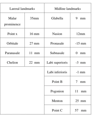
Table 8: Patient 2 post surgical values
Lareral landmarks Midline landmarks
Malar prominence
35mm Glabella 9 mm
Point x 16 mm Nasion 12mm
Orbitale 27 mm Pronasale -15 mm
Paranasale 11 mm Subnasale 0 mm
Chelion 22 mm Labi superioris -3 mm
Labi inferioris -1 mm
Point B 7 mm
Pogonion 11 mm
Menton 25 mm
Point C 57 mm
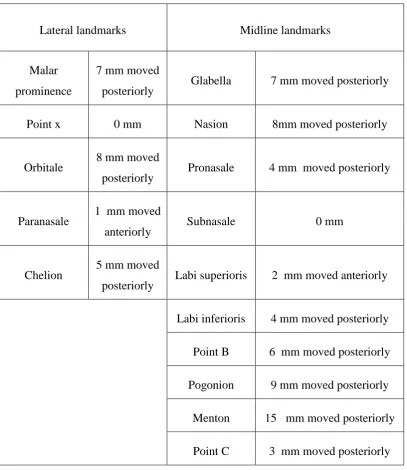
Table 9: Soft tissue changes of patient 2 six months after surgery
Lateral landmarks Midline landmarks
Malar prominence
7 mm moved
posteriorly Glabella 7 mm moved posteriorly
Point x 0 mm Nasion 8mm moved posteriorly
Orbitale 8 mm moved
posteriorly Pronasale 4 mm moved posteriorly
Paranasale 1 mm moved
anteriorly Subnasale 0 mm
Chelion 5 mm moved
posteriorly Labi superioris 2 mm moved anteriorly
Labi inferioris 4 mm moved posteriorly
Point B 6 mm moved posteriorly
Pogonion 9 mm moved posteriorly
Menton 15 mm moved posteriorly
Point C 3 mm moved posteriorly
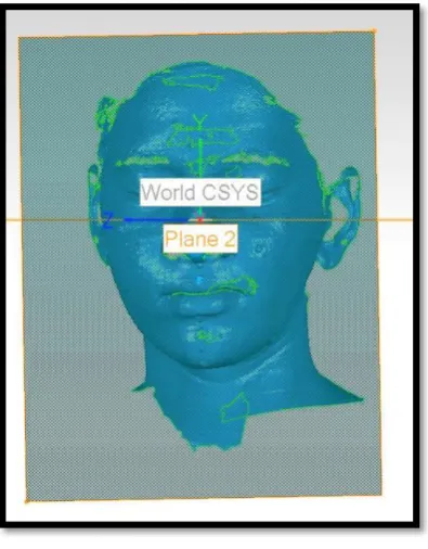
PATIENT 2: (PRE SURGICAL LASER SCAN)
Fig.18: FRONTAL VIEW
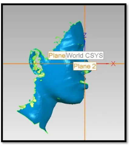
[image:57.595.191.404.452.696.2]Fig.20: LEFT LATERAL VIEW
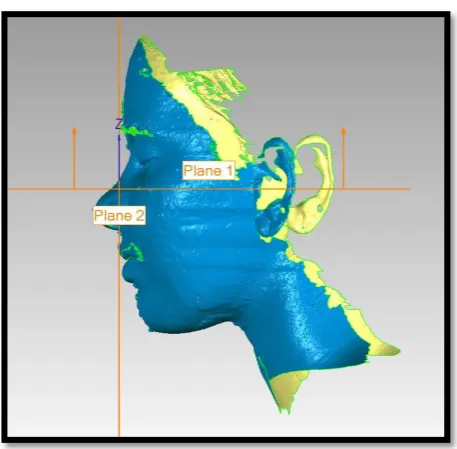
PATIENT 2: (POST SURGICAL SCAN)
[image:58.595.199.397.444.697.2]Fig.22: RIGHT LATERAL VIEW
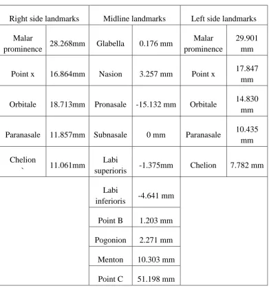
[image:59.595.183.412.464.688.2]Table 10: Patient 2 Presurgical values (length of vectors projected from True Vertical Plane to each landmarks. Landmarks ahead of true vertical
plane give negative values)
Right side landmarks Midline landmarks Left side landmarks
Malar
prominence 28.268mm Glabella 0.176 mm
Malar prominence
29.901 mm
Point x 16.864mm Nasion 3.257 mm Point x 17.847
mm
Orbitale 18.713mm Pronasale -15.132 mm Orbitale 14.830
mm
Paranasale 11.857mm Subnasale 0 mm Paranasale 10.435
mm
Chelion
` 11.061mm
Labi
superioris -1.375mm Chelion 7.782 mm
Labi
inferioris -4.641 mm
Point B 1.203 mm
Pogonion 2.271 mm
Menton 10.303 mm
Point C 51.198 mm
Table 11: PATIENT 2 POST SURGICAL VALUES
Right side landmarks Midline landmarks Left side landmarks
Malar
prominence 28.030mm Glabella 1.971 mm
Malar
prominence 16.939 mm
Point x 16.524mm Nasion 4.321 mm Point x 5.818 mm
Orbitale 17.388mm Pronasale -14.962mm Orbitale 10.251mm
Paranasale 10.570mm Subnasale 0mm Paranasale 4.716 mm
Chelion 16.199mm Labi
superioris -0.577mm Chelion 11.269 mm
Labi
inferioris 9.193mm
Point B 9.875mm
Pogonion 11.890mm
Menton 18.409mm
Point C 68.416mm
Table 12: Soft tissue changes of patient 2 six months after surgery
Right side landmarks Midline landmarks Left side landmarks
Malar prominence 0.238MM moved anteriorly Glabella 1.795mm moved posteriorly Malar prominence ` 12.962mm moved anteriorly Point x 0.34mm moved anteriorly Nasion 1.064 mm moved posterior Point x 12.029mm moved anteriorly Orbitale 1.325 mm moved anteriorly Pronasale 0.17mm moved posteriorly Orbitale 4.579mm moved anteriorly Paranasale 1.287 mm moved anteriorly
Subnasale 0mm Paranasale
[image:63.595.225.372.112.309.2]
PATIENT 3: PRESURGICAL LATERAL CEPHALOGRAM
MEASUREMENTS
Fig.24: Patient 3 undergone Lefort 1 set up and set back
[image:63.595.222.367.451.646.2]
Table 13: Patient 3 presurgical values(length of vectors projected from true vertical line to each landmarks. Landmarks ahead of true vertical line give negative values)
Lateral landmarks Midline landmarks
Malar
prominence
29 mm Glabella 4 mm
Point x 21 mm Nasion 6 mm
Orbitale 20 mm Pronasale -15 mm
Paranasale 12 mm Subnasale 0 mm
Chelion 22 mm Labi superioris -3 mm
Labi inferioris 10 mm
Point B 17 mm
Pogonion 22 mm
Menton 38 mm
Point C 83 mm
[image:64.595.134.463.277.612.2]Table 14: Patient 3 post surgical values
Lateral landmarks Midline landmarks
Malar prominence 36mm Glabella 0 mm
Point x 20 mm Nasion 3 mm
Orbitale 16 mm Pronasale -18 mm
Paranasale 11 mm Subnasale 0 mm
Chelion 22 mm Labi superioris 1 mm
Labi inferioris 8 mm
Point B 14 mm
Pogonion 18 mm
Menton 32 mm
Point C 92 mm
Table 15: Soft tissue changes of patient 3 six months after surgery
Lateral landmarks
Midline landmarks
Malar prominence 7 mm moved
posteriorly Glabella
4 mm moved anteriorly
Point x 1 mm moved
anteriorly Nasion
3mm moved anteriorly
Orbitale 4 mm moved
anteriorly Pronasale
3 mm moved anteriorly
Paranasale 1 mm moved
anteriorly Subnasale 0 mm
Chelion 0mm Labi superioris 4 mm moved
posteriorly
Labi inferioris 2 mm moved
anteriorly
Point B 3 mm moved
anteriorly
Pogonion 4 mm moved
anteriorly
Menton 6 mm moved
anteriorly
Point C 9 mm moved
posteriorly
PATIENT 3: (PRE SURGICAL SCAN)
Fig.27: RIGHT LATERAL VIEW
[image:68.595.173.423.402.635.2]PATIENT 3: (POST SURGICAL SCAN)
Fig.29: FRONTAL VIEW
[image:69.595.140.456.478.678.2]Table 16: Patient 3: Presurgical values(length of vectors projected from truevertical plane to each landmarks. Landmarks ahead of true vertical
plane give negative values)
Right side landmarks Midline landmarks Left side landmarks
Malar prominence
44.526mm Glabella 1.754 MM Malar prominence
19.397MM
Point x 20.707mm Nasion 3.482 MM Point x 11.723MM
Orbitale 20.671mm Pronasale -16.557 MM Orbitale 11.778MM
Paranasale 14.101mm Subnasale 0 MM Paranasale 8.871MM
Chelion 24.035mm Labi superioris
-0.940MM Chelion 16.302MM
Point B 17.353 MM
Pogonion 21.607 MM
Menton 31.635 MM
Point C 77.116 MM
Table 17: Patient 3 post surgical values
Right side landmarks Midline landmarks Left side landmarks
Malar
prominence 39.467MM Glabella 0.424 MM
Malar
prominence 7.150 MM
Point x 24.198
MM Nasion 2.310 MM Point x 2.635 MM
Orbitale 23.399MM Pronasale -14.469MM Orbitale 4.909 MM
Paranasale 14.517MM Subnasale 0MM Paranasale 4.832 MM
Chelion 27.092MM Labi
superioris 0.914MM Chelion 9.358 MM
Labi
inferioris 6.757 MM
Point B 12.614 MM
Pogonion 15.183 MM
Table 18. Softtissue changes of patient 3 six months after surgery
Right side landmarks Midline landmarks Left side landmarks
Malar prominence 5.057mm moved anteriorly Glabella 1.33 mm moved anteriorly Malar prominence 12.247 MM anteriorly Point x 3.419mm moved posteriorly Nasion 1.172mm moved anteriorly Point x 9.088 moved anteriorly Orbitale 2.728mm moved posteriorly Pronasale 2.088 mm moved posteriorly Orbitale 6.869 mm moved anteriorly Paranasale 0.416mm moved posteriorly
Subnasale 0mm Paranasale
49
DISCUSSION
Soft tissue changes are inevitable outcome of most of maxillofacial
surgical procedures. Assessment of soft tissue changes is a challenge for
maxillofacial surgeons. These assessments and soft tissue response help
surgeons to predict possible outcome of the surgical procedure. Hard tissue
movements during maxillofacial surgery will definitely affect the soft tissue of
face. Patient is mainly concerned of their soft tissue outcome than hard tissue
movements. Patient can appreciate the soft tissue change only after the
surgery. Soft tissue change assessment can be done in different methods.
1) LATERAL CEPHALOGRAM
Lateral cephalogram is the traditional tool used to evaluate soft tissue
changes by surgeons. Most popular techniques are Arnett and Bergman
analysis, Burston soft tissue analysis, Hold Away analysis etc. Pre surgical and
post surgical cephalometric studies give an idea about soft tissue changes of
patients after surgical procedure. Anatomical landmarks are identified by
placing metal markers and a cephalostat is used to keep the head position in
the same position for pre operative and post operative cephalometric x-ray
Cephalometrics can be used as an aid in the diagnosis of skeletal and
dental problems and a tool for simulating surgery by the use of acetate paper
50
Disadvantages are, it represents 2D aspect of a 3D object. It represents
only midline structures clearly. Landmarks like chelion is very difficult to
identify, due to radio opaque orthodontic bracket overlap. Bilateral
representation of non midline land marks is not possible. Cephalogram is not
easy to store for a long time. Quality of film may change over a period of time.
To avoid such difficulties in soft tissue analysis, surgeons prefer 3D
SOFTTISSUE RECONSTRUCTION techniques such as Photogrammetry, 3D
Laser scanners,White light 3d scanning, Facial Moulage
2) FACIAL MOULAGE
Casts moulded from direct facial impression are ease of availability
ease of manoeuvrability, no radiation exposure, cost effective and accurate.
Disadvantages are cumbersome procedure, no any definitive assessment
procedure, assessment done only by visualisation, difficulty in storage, weight
of dental stone may distort alginate facial impression, patient cooperation is
necessary, and difficult to transport.
3) PHOTOGRAMMETRY
It has been defined by the American Society for Photogrammetric and
Remote Sensing (ASPRS) as the art, science, and technology of obtaining
reliable information about physical objects and the environment through
processes of recording, measuring and interpreting photographic images and
51
Photogrammetric is more accurate in the x, y and z direction. It provides a
permanent photographic record. Disadvantages are it needs sophisticated
instruments and very costly
4) CT 3D CEPHALOMETRY
The acquired CT images are stored in DICOM (Digital Imaging and
Communications in Medicine) format. It can be imported into any
software. Advantages: (1) real-size and real-time 3D cephalometric
analysis, (2) truly volumetric 3D depiction of hard and soft tissues of
the Skull, (3) high accuracy and reliability, and (4) no superimposition
of anatomic structures. A high end computer is needed to reconstruct
the CT data. A Pentium CPU with 1GB memory is a must38.
CT 3D Cephalometry has marked advantages over conventional
cephalometry, data acquisition still has some drawbacks: (1) horizontal
positioning of the patient during record taking falsifies the position of
the soft tissue facial mask, (2) lack of a detailed occlusion due to
artefacts, (3) limited access for the routine craniofacial patient because
of relatively higher cost, and (4) higher radiation exposure than other
52
5) CBCT 3D CEPHALOMETRY
It has some interesting advantages for the future:
1) Reduced radiation exposure, natural shape of the soft-tissue facial
mask because of the vertical scanning procedure.
2) Reduced artefacts at the level of the occlusion,
3) Increased access for the routine dento facial patient because of
in-office imaging. To be installed in oral surgery outpatient clinics and
private practices
4) Reduced costs.
The current limitations of CBCT 3D cephalometry are the scanning
volume and positional dependency of the image value of a structure in
the field of view of the scanner24.
6) WHITE LIGHT 3D SCANNING
White light scanning is a 3D scanning technology that uses white light
source to project fringes onto the object being scanned. The sensor of
the white light scanner takes multiple images of the object during
measurement and sends these images through software that triangulates
the 3D coordinates of numerous points spaced all over the surface of
53 Advantages are
1) Creates a very high density point cloud.
2) Can scan small parts with intricate details.
Disadvantages are
1. It requires photogrammetry targets and/or surface spray
2. Structured measurement environment - no freeform measurement
3. Lengthy setup and post processing time
4. Must 'stitch' snapshots together using photogrammetry techniques or
post processing software
5. Limited to scanning - no dynamic tracking or probing capabilities
7) 3D LASER SCANNING
Laser scanners are very analogous to cameras. Like cameras, they have
a cone-like field of view, and like cameras, they can only collect information
about surfaces that are not obscured. While a camera collects colour
information about surfaces within its field of view, a 3D scanner collects
distance information about surfaces within its field of view. The picture
(OBJECT) produced by a 3Dscanner describes the distance to a surface at
each point in the object. This allows the three-dimensional position of each
point in the object to be identified to a common point in a given plane89.This
54
reconstruction. The polygonal mesh derived from a 3D scanner can be used
for reverse engineering, to make changes to prototypes, or even create moulds
and dies. Complex surface structures are easily captured as a polygonal mesh
by 3Dscanners. The polygonal mesh can be converted to a format native to
various CAD applications. Once converted, CAD can be used to make slight
adjustments to the original object for better fitment or make even more
dramatic changes such as combining a polygonal mesh with CAD objects to
create personalized ergonomic parts. Simple moulds can be made by
subtracting the polygonal mesh from a box with a part line. The resulting CAD
model can be quickly fabricated using Rapid Prototyping machines and used
to pour various materials.Advantages include, it gives more accurate soft
tissue reproducibility, Easy manuverability, better reproduction of details, easy
reconstruction of 3d image, and no radiation exposure89. Disadvantages of
laser scanner unit are, not cost effective, lack of availability of technology,
unavailability of cephalostat like head positioning system, the size of scanned
files.
Although laser scanners produce flawless data results that can be
edited and repurposed in a variety of ways using polygon mesh models, solid
surface models and solid CAD models, it needs high-end computer hardware
to accommodate the significant memory requirements of the data. 3D laser
scanning costs more; still 3Dlaser scanning is an ideal tool for soft tissue
55
complex three-dimensional shapes, such as the face, accurately and rapidly. It
has significant advantages over existing two- and three-dimensional methods
of facial soft-tissue analysis and would seem to be a very suitable technique
for measuring the three-dimensional changes in facial surface anatomy
resulting from orthognathic surgery.
Orthognathic surgery is the most popular surgical field of maxillofacial
surgery to improve patients function and aesthetics. All these procedures
results in marked skeletal movements. Soft tissue change depends on the
skeletal movement. Exact soft tissue change prediction is almost impossible.
Because soft tissue response may vary from person to person, soft tissue
changes depends on inflammatory response, presurgical tissue thickness,
severity of instrumentation, nutritional factors, post op care and a lot of other
factors. Soft issue changes can effectively evaluate using 3D facial
reconstruction techniques like laser scanning76. This technique is more
superior compared to Lateral Cephalogram based evaluation. The software
which reads the 3D data loaded with lot of features and measuring tools,
provides options for plane creation, vector projection, point projections, angle
measurements, length measurements, volumetric assessments &
superimposition.
Application of laser scanning is not limited to orthognathic surgery
56
Plastic surgeons, cosmetic surgical specialists, and orthodontists also prefer
this technique to assess their treatment outcome79, 67.
Soft tissue changes also occur in cleft lip repair, alveolar bone
grafting, malar augmentation, muscle debulking surgeries, liposuctioning
surgeries, fat transfer surgeries, dental implantology related surgeries, tumour
& cyst management, cancer related resection and reconstruction surgeries.
Facial aesthetic surgeries like facelift, brow lift, blepharoplasty etc66.
Studies evaluating post operative swelling can be effectively measured
using pre and post surgical laser scanner. Software provides an option called
superimposition of scanned image. Both pre and post surgical scans
superimpose and merged together, and changes evaluated by software. Such
studies shows more accurate results than conventional studies.11
Storing dental casts are very important in clinical practice. These casts
help surgeon for future references. But this plaster models are difficult to store
in normal clinical set up. Changes due to chipping of model also can happen.
These dental cast scan be valuable evidence in medico legal cases. Forensic
experts may need dental casts for their investigations. In such conditions
instead of keeping all models, surgeon can make use of 3D laser scanner to
scan all dental casts, as this is digital data; can be stored in a compact disc or
in a pen drive. Whenever it is required surgeon can fabricate a
57
In cleft lip cases, scanned 3D facial data helps surgeon to evaluate the
defect properly. Cleft lip, nasal deformities can be studied in computer and
surgeon can plan his surgical technique according to that. Rubber based
replica of the scanned image can be used as an effective tool to try incision
plans, flap rotations before surgery 21.
Laser scanner is used for the evaluation of postoperative changes of
soft tissue swelling after different anti inflammatory drug administration34 .
Laser scanning is effectively used in anthropometric studies. Landmark
placement and accuracy in measurement is more in this technique. It reduces
the processing time markedly6. Laser scanning used in Studies focusing on
reproducibility of landmarks on face. Operator error in reproducing land mark
can be compared to internationally accepted gold standards using 3D laser
imaging technology10.
Laser scanning superimposition technique can be used to assess soft
tissue changes in single jaw and double jaw surgeries. Quantitative volumetric
changes calculated by superimposition of pre and post operative 3D data.11.
Three-dimensional facial morphologic changes of children can be assessed
effectively using laser scanning device. This technology helps craniofacial
surgeons to create templates for comparing different craniofacial anomalies15.
Surgeon can evaluate effect of Botulinum toxin on Masseteric
hypertrophy management using pre and post treatment laser scanning .this