I hereby declare that I have read through this report entitle “GUI Development of Solar Energy
Flow for Stand Alone System” and found that it has comply the partial fulfillment for awarding
the degree of Bachelor of Electrical Engineering (Industrial Power)”
Signature : ...
Supervisor’s Name : NORHAFIZ BIN SALIM
MUHAMAD IZZAT BIN AB HALIM
A report submitted in partial fulfillment of the requirements for the degree of the Bachelor of Electrical Engineering (Industrial Power)
Faculty of Electrical Engineering
UNIVERSITI TEKNIKAL MALAYSIA MELAKA
STUDENT DECLARATION
I declare that this report entitle “GUI development of Solar Energy Flow for Stand Alone
System” is the result of my own research except as cited in the references. The report has not
been accepted for any degree and is not concurrently submitted in candidature of any other degree.
Signature : ...
Name : MUHAMAD IZZAT BIN AB HALIM
ACKNOWLEDGEMENT
Praise be to Allah S.W.T to whom we seek help and guidance and under His benevolence we exist and without His help this project could not have been accomplished.
ABSTRACT
ABSTRAK
TABLE OF CONTENTS
CHAPTER TITLE PAGE
ACKNOWLEDGEMENT i
ABSTRACT ii
TABLE OF CONTENTS iv
LIST OF TABLES vii
LIST OF FIGURES viii
LIST OF SYMBOLS xi
LIST OF APPENDICES xii
1 INTRODUCTION
1.1Introduction 1
1.2Problem Statement 2
1.3Project Objective 2
1.4Project Scope 2
2 LITERATURE REVIEW
2.1Introduction 3
2.2Development of Graphic User Interface (GUI) 3 2.2.1 Visual Basic (VB) 4
2.2.2 MATLAB 5
2.3.1 PV Module 7 2.3.1.1 Basic Type of Common Solar 8 2.3.1.2 Solar Cell Model 9 2.3.2 Charger controller 10
2.3.2.1 Characteristic of Charger Controller 11 2.3.2.2 Operating Principle of Charging 12
Discharging Protector
2.3.3 Inverter 14
2.3.3.1 Form of Electric Wave Produce 15 2.3.3.2 Inverter Characteristic 16
2.3.4 Batteries 17
2.3.4.1 General Motions of Battery 17 2.3.4.2 Model of Battery 19
2.4PIC Microcontroller 19
2.4.1 PIC 16F877A 20
2.5Technology of Monitoring PV System 21
2.6Conclusion 21
3 METHODOLOGY
3.1Introduction 22
3.2First Stage 24
3.3Second Stage 24
3.4Third Stage 31
3.5Forth Stage 33
3.5.1 Simulation 33
3.5.2 Hardware 35
4.1Introduction 39
4.2Software 39
4.2.1 Simulation Result 46
4.3Hardware 47
4.4Result 48
4.4.1 CASE 1: Comparison Solar Panel 12v, 1 watt 48 and 12v, 10 with GUI and Actual Measurement 4.4.2 CASE 2: Comparison PV Module 22V, 60 56
Watt Mono Crystalline Type and 22v, 60 Watt Amorphous Type
4.4.3 CASE 3: 22V, 60watt Mono Crystalline Type 60 at Different Temperature
5 DISCUSSION
5.1 Introduction 65
5.2 Discussion 65
6 CONCLUSION AND DISCUSSION
6.1 Conclusion 69
6.2 Recommendation 70
REFERENCES 71
LIST OF TABLE
TABLE TITLE PAGE
2.1 Characteristic of Charger Controller 11 2.2 Basic Component of Inverter 14 2.3 General Notions for Battery 18 4.1 Table PV Module 12V, 1Watt and Mono 49
Crystalline Type
4.2 PV Module 12V, 10Watt and Mono Crystalline Type 52 4.3 Comparison Different Type of PV Module 57
4.4 Result First Week 60
LIST OF FIGURE
FIGURE TITLE PAGE
2.1 VB GUI 5
2.2 Matlab GUI 6
2.3 Stand Alone Solar System Component 7
2.4 PV module 8
2.5 Model of Single Solar Cell 9
2.6 Charger Controller 11
2.7 Operating Principle of Overcharge Protection 13 2.8 Operating Principle of Discharging Protection 13 2.9 Block Diagram of Solar Inverter 14
2.10 Battery 17
2.11 Model of Battery 19
2.12 PIC 16F877A 20
3.1 Flow Chart of Methodology 23
3.2 VB Create New Project 25
3.3 VB Toolbox 26
FIGURE TITLE PAGE
3.5 Window Code 27
3.6 Protection Form 28
3.7 Code for Protection 29
3.8 Main Menu Form 30
3.9 Code for Main Menu 31
3.10 Component for Stand Alone System 32
3.11 Proteus Circuit Design 34
3.12 Hardware of Monitoring System 35
3.13 Switching Circuit 36
3.14 Temperature Sensor 36
3.15 Integration between VB and Proteus 37
3.16 Overall System 38
4.1 GUI Interface 40
4.2 Coding for Micro C 41
4.3 Coding for Micro C 42
4.4 Coding for Micro C 42
4.5 Coding for VB 43
4.6 Display of date and time 44
4.7 Coding for Date and Time 44
4.9 Connectivity of COM Port 45
4.10 Simulation Result 46
4.11 Hardware result 47
4.12 Voltage Graph Obtain by GUI and Actual 50 4.13 Current Graph Obtain by GUI and Actual 50 4.14 Power Graph Obtains by GUI and Actual 51 4.15 Voltage Graph Obtains by GUI and Actual 53 4.16 Current Graph Obtains by GUI and Actual 53 4.17 Power Graph Obtains by GUI and Actual 53
4.18 Comparison Voltage Graph 55
4.19 Comparison Current Graph 55
4.20 Comparison Power Graph 56
LIST OF SYMBOL
m - Idealizing factor is Boltzmann’s T c - absolute temperature of the cell e - Electronic charge
V - Voltage imposed across cell Io - dark saturation current
LIST OF APPENDICES
APPENDIX TITLE PAGE
CHAPTER 1
INTRODUCTION
1.1 Introduction
i. The increasing of electricity bill and unable to manage power consumption ii. Difficult to do maintenance and troubleshooting
iii. Unable to take measurement at difficult area
iv. Unable to continuous monitoring system performance
1.3 Project Objective
The objectives of this project are:
i. To study the graphical user interface of solar energy flow. ii. To develop hardware of solar system and software for the GUI. iii. To analysis voltage, current and power flow in the solar system.
iv. To conclude that GUI can show the exact amount of energy produce, store and used.
1.4 Project Scope
CHAPTER 2
LITERATURE REVIEW
2.1 Introduction
Solar energy has become important and widely used because of soaring fossil fuel gas and increased environmental pollution. There are many advantages by using solar energy like environment friendly, silent and required low maintenance, however there are also disadvantage of solar energy. Solar energy required high initial cost and the power produce depend on the weather. So, further study and research was developed in order to overcome this problem. In this chapter the latest journal research had been done to help development of this project.
2.2 Development of Graphic User Interface (GUI)
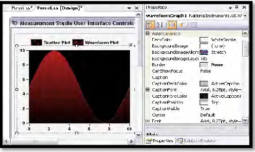
Microsoft Visual basic 6.0 is window programming language application of old Basic language. VB can be used to develop system in one package from the simples to complicated ones. Hence VB will be able to edit, write and test window applications. Besides that VB also include tool that can be use to write and compiles help file, active x control and even internet application. VB is most attractive software because it is the combination between graphic programming and code programming.
Figure 2.1: VB GUI
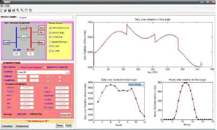
2.2.2 MATLAB
MATLAB (matrix laboratory) is the most popular software for engineering student. MATLAB represent with an interactive numerical computation environment, matrix computation, graphics, programming, toolboxes and other. MATLAB has many advantages to user because it is very easy, inexpensive software and fast numerical algorithms. The MATLAB software also include GUI that will be able to design PV stand alone system.
Figure 2.2: MATLAB GUI
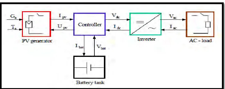
2.3 Component of Standalone Solar System
Figure 2.3: Stand Alone Solar System Component
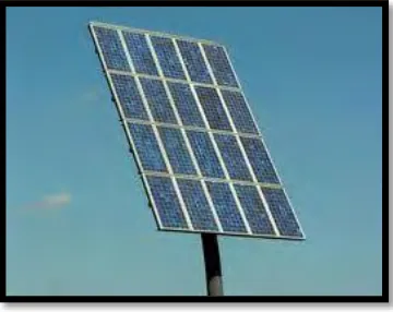
2.3.1 PV Module
Figure 2.4: PV module
2.3.1.1 Basic Type of Common Solar
There are 3 basic type of common solar; panel mono crystalline silicon solar cells, polycrystalline silicon solar cells and amorphous silicon solar cells.
i. Mono Crystalline silicon
The mono crystalline solar panel was made in mono crystalline cell. It element contain pure silicon and involve complicated crystal growth process. The silicon was cut into slice about of 0.2 to 0. 4 mm thick discs or wafers and then all the individual silicon were combine and wired together in the solar panel. The mono crystalline silicon will produce most efficient method compare to other but the disadvantage is, it was too expensive.
ii. Polycrystalline solar panels