8-1963
Multipactoring at a single electrode
Donald Ray FinchIowa State University E. L. Iloff
Iowa State University
Follow this and additional works at:http://lib.dr.iastate.edu/ameslab_isreports Part of theElectrical and Electronics Commons
This Report is brought to you for free and open access by the Ames Laboratory at Iowa State University Digital Repository. It has been accepted for inclusion in Ames Laboratory Technical Reports by an authorized administrator of Iowa State University Digital Repository. For more information, please [email protected].
Recommended Citation
Abstract
that occurs at the surface of a single flat plate electrode. The process occurs in a combined d. c. and v. h. f. field and is of the type commonly known as multipactoring. Electrons move outward from a multiplying electrode under the influence of the v. h. f. field which is larger in magnitude than the d. c. field. After the v. h. f. field reverses the electrons stop and are accelerated back to the multiplying electrode by the combined fields. Upon striking the multiplying electrode more than one secondary electron is emitted which under the proper conditions can repeat the above motion yielding ultimately a large increase in number of electrons. A simple theory of the mechanism is presented which includes conditions for stability of the multiplying process as well as a description of the motion of the electrons in the process. A method of specifying all field parameters is presented which enables these parameters to be quickly specified for experimental work. The experimental work presents a good verification of the theory of the mechanism; in particular, the stability conditions are well confirmed from the experimental results. A discussion of competing types of gas discharges and
multiplying mechanisms is presented which enables a clear understanding of the detailed mechanisms that are occurring to be achieved.
Disciplines
Electrical and Electronics
IOWA STATE UNIVERSITY
MULTIPACTORING AT A SINGLE ELECTRODE
by
Donald Ray Finch and E. L. Iloff
RESEARCH AND
DEVELOPMENT
REPORT
UNITED STATES ATOMIC ENERGY COMMISSION Research and Development Report
MULTIPACTORING AT A SINGLE ELECTRODE
by
Donald Ray Finch and E. L. Iloff
August, 1963
Ames Laboratory at
Iowa State University of Science and Technology F. H. Spedding, Director
IS -743
This report is distributed according to the category Physics (UC -34) as listed in TID-4500, April 1, 1964.
Legal Notice
This report was prepared as an account of Government sponsored work. Neither the United States, nor the Commission, nor any person acting on behalf of the Commission:
A. Makes any warranty or representation, expressed or implied, with respect to the accuracy, completeness, or usefulness of the information contained in this report, or that the use of any information, apparatus, method, or process disclosed in this report may not infringe privately owned rights; or
B. Assumes any liabilities with respect to the use of, or for damages resulting from the use of any information, apparatus, method, or process disclosed in this report. As used in the above, "person acting on behalf of the Commission" includes any employee or contractor of the Commission, or employee
of such contractor, to the extent that such employee or contractor of the Commission, or employee of such contractor prepares, dissemi-nates, or provides access to, any information pursuant to his employ-ment or contract with the Commission, or his employemploy-ment with such contractor.
Printed in USA. Price $ 2. 50 • Available from the Office of Technical Services
IS -743
TABLE OF CONTENTS
Page
ABSTRACT. . • . . • . • • • • . • . . • • . . • . . . • . . • • • • . • • . . • • • . . • • . • . • • • v
I. INTRODUCTION AND REVIEW OF PREVIOUS WORK... 1
II. REVIEW OF TWO ELECTRODE MULTIPACTORING • • • • • • • 12 III. THEORY OF SINGLE ELECTRODE MULTIPACTORING 31 A. Equation of Motion and Solutions for Electron Arrival Phases . . . . . . . . 31
B. Phase Stability and Existence Regions... 40
C~ Electron Return Energy... 49
D. Electron Path R.elations... 54
E. Specification of Parameters... 57
IV. EXPERIMENTAL WORK • • • • • • • • • • • • • • • • • • • • • • • • • • • • • • • • 62 A. Apparatus . . . . 62
B. Techniques of Measurement... . • . . • . . 70
V. EXPERIMENTAL RESULTS • • • . • • • . • • • . • • • • • • • • • • • . • • • . • 76 VI. ANALYSIS OF EXPERIMENTAL RESULTS • • • • • • • . • . • • • • • • 88 VII. CONCLUSIONS . . . . 99
IS -743
*
MULTIPACTORING AT A SINGLE ELECTRODE' Donald Ray Finch and E. L. Iloff
ABSTRACT
This study presents a new type of electron multiplying phenomenon that occurs at the surface of a single flat plate electrode. The process occurs in a combined d. c. and v. h. f. field and is of the type commonly known as multipactoring. Electrons move outward from a multiplying electrode under the influence of the v. h. f. field which is larger in mag-nitude than the d. c. field. After the v. h. f. field reverses the electrons stop and are accelerated back to the multiplying electrode by the com-bined fields. Upon striking the multiplying electrode more than one secondary electron is emitted which under the proper conditions can repeat the above motion yielding ultimately a large increase in number of electrons. A simple theory of the mechanism is presented which includes conditions for stability of the multiplying process as well as a description of the motion of the electrons in the process. A method of specifying all field parameters is presented which enables these param-eters to be quickly specified for experimental work. The experimental work presents a good verification of the theory of the mechanism; in particular, the stability conditions are well confirmed from the experi-mental results. A discussion of competing types of gas discharges and multiplying mechanisms is presented which enables a clear understand-ing of the detailed mechanisms that are occurrunderstand-ing to be achieved.
I. INTROOU::T ION ANl REVIEW Of PREVIOUS WORK Multipactorini ia • name aometimea used to denote a specific class of electron multiplying phenomena that occur between electrodes in vacuum due to very high frequency elec• tric fields.
A two electrode multipactoring phenomenon, thot has been the subject of many previous studies, ia easily described with the aid of Figure 1. A simplified diagram of electrode geometry and electrical connections suitable for studying moat v.h.f. discharges ia shown in Figure la. If a sinusoidal
voltage, as shown in Figure lb, is applied to electrode 1 of Figure la by the generator, a multipactoring oscillation can
occur between the two electrodes in the following mannera a. An electron originating from electrode 11 or a free
electron in the vicinity of electrode 11 after time phase zero will be accelerated toward electrode 2. b. Providing the mean free path of the electron is
sufficiently long in the vacuum, and the electrode spacing i& sufficiently short the electron may collide with electrode 2.
c. If the electron, in the transition to electrode 2, has picked up a sufficient amount of energy, then one or more secondary electrons may be emitted froa electrode 2.
Figure la. Simple electrode geometry and electrical connec-tions for study of v.h.f. discharges
Figure lb. Sinusoidal potential used to study two electrode multipactoring
2
a
v,~
I
'
(rj0
.,.,2
3 .,.,2
I-v.
b
0
211'
juat aueh •• to have allowed one half cycle to be
completed the electric field will have reveraed and
the aecondary electron• may be accelerated back
toward electrode 1.
e. A repetition of b, c, and d may now occur eventually
leading to the development of a large cloud of
electron& if the emiasion coefficient• of the
aur-faces are greater than one.
Thia form of multipactoring oscillation haa been investigated
by a large numbe~ of persona, and the details of the mechanism
are well eatablished.
A second type of multipactoring oacillation may alao
occur in which the multiplying takes place at only one
elec-trode. This type of multipactoring phenomenon has not been
studied previously, and is the subject of thia work. Consider
the motion of an electron in the field resulting from the
superposition of an alternating potential on a d.c. potential
as shown in Figure lc. If this potential is applied to
electrode 1 of Figure la a multipactoring oscillation using
only electrode 1 aa a multiplying surface can occur in the
following mannera
a. An electron originating from electrode 1, or a free
electron in the vicinity of electrode 1, after time
phase
+
in Figure lc will be accelerated towardlarge, the electron will be accelerated until time
phaae 8 of figure le. At thia time the electric
field rever•••• and the electron decelerates and
finally atopa.
e. The electron ia then accelerated back to electrode
1 where, if it arrives with sufficient enerQYt it
may produce one or more secondary electrons upon
impact.
d. If the secondary electrons are emitted at a time
phase e·qual to or later than ' the process can
repeat itself eventually leading to the build up
of a large cloud of electrons multiplying themselvea
on electrode 1 only.
A mathematical formulation of thia sinQle electrode
multipac-toring will be developed below, and the conditions under which
a stable oscillation of electrons can occur will be determined.
Multipactoring oacillations form the major breakdown
mechanism observed in low pressure v.h.f. gas discharge work.
Low pressure in thia case means pressures low enough so that
the electron mean free path ia substantially larger than the
separation of the electrodes producing the v.h.f. fields, In
the years 1900 to 1930 a larQe volume of work was performed
in determining the phenomenological aspects of gaa dischargea
was the determination of breakdown potential• ·of glow·dia•
chargea (i.e. light emitting dischargea) aa a function of the
r.f. field, gas pressure, and type of gaa.
It must, however, be observed that in moat of the work
prior to 1930 it is difficult to believe that a pure
muiti-pactoring type of mechanism was being observed. The vacuum
pressures at which the experiments were carried out normally
allowed electron mean free paths at moat equal to the
elec-trode separation used. What was actually happening would be
very hard to pin down inasmuch as quite a variety of
proces-~es ranging from simple recombination mechanisms in the gas
to extremely complex mechanisms could have occurred at these
gas pressures. In addition, along with the occurrence of a
glow discharge go ion c~nduction and space charge effects
which act to destroy the voltage relationships necessary for
the maintainance of a multipactoring oscillation.
The first suggestion of an electron oscillation as a
mechanism for the breakdown of the gas was made by Holm (13)
in 19lo. The idea was used by several persons, but was
primarily developed by Gutton ~' 9, 10) and Kirschner (14, 15).
The results of research to 1930 were summarized by Gutton (10)
as followsa
a. For wavelengths greater than 200 meters, breakdown
potentials are the same as for d.c. discharges.
preaiure exiata for which the breakdown potential ia
very low in any particular gaa, Thia breakdown
poten-tial ia alao a atrong function of the type of gaa and
the electrode aeparation.
c, For wavelengths leas than 30 m. an electron resonance
mechaniam becomes dominant which enables ionization
by electron colliaion to occur.
At the time Gut ton stated these reaul ts., no quantitative
theory of the discharges had been attempted beyond some almost
qualitative estimates. The first real work on a mathematical
theory of the mechanism waa done by Henneburg
!1
!!·
(12) in1936. This work considered the two electrode oscillation with
the assumption that all the electrons emitted from the surface&
leave with zero initial energy. This assumption is not
physi-cally truea however, the results of this work were sufficient
to give a clear insight into the mechanism, and are, of course,
a special case of a -more general formulation taking account of
the initial electron energy.
A separate piece of work was done by Backmark and Bengston
(2) who attempted to extend the results of other investigations
to lower pressures. Most of their results were consistent with
prior work. Their work included a simple theory which along
with later work by Danielsson(4) gave a few rules of a
semi-empirical naturea however, not quantitatively as good as the
The firat work to account for the initial electron energy
waa done by Gill and von Engel {6) in 1948. They assumed that
the ratio of emitted electron energy to primary electron
energy was constant, and proceeded to apply the results to
breakdown phenomena in the same pressure region so thoroughly
studied previously. Their quantitative work was able to
account for some, but not all, of their experimentally observed
results. Their experimental work was of interest primarily
because it demonstrated fairly conclusively that the
break-down mechanism was due to electrons in a multipactoring oscil•
lation. Hatch and Williams (11) attempted to extend the
ex-perimental results of Gill and von Engel to very low vacuum
pressures (i.e. about 10-6 torr.)a however, in doing so were
required to make ad ~.assumptions concerning the parameters that appear in the Gill and von Engel work thereby partially
negating the value of their work. The experimental technique
used by Hatch and Williams, however, was very good, and some
of their observations will later be seen to have some
correla-tion with the present work.
The work that produced a full mathematical description
of the two electrode multipactoring mechanism with
experimen-tal verification was done by Krebs
!1
al. (17, 18, 19, 20, 21,22). They used the ~ame methods as Henneburg ~
!!·
(12)reformulated so as to give a better qualitative insight into
the mechanism as well as making quantitative work easier.
independent of the particular gas present eo long as the
pressure i1 low enough to assure an electron mean free path
muchlarger than the electrode separation. A more detailed review of
this work will be presented in Chapter II.
Very few practical applications of multipactoring
oscil-lations have been made. This is probably due, for the most
part, to the fact that little advantage is presented by using
a multipactoring oscillation instead of some other equally
applicable technique. The first known application was by
Farnsworth (~) who used the mechanism for amplification in an
image scanning system for use in television. The system never
reached any wide acceptance due to the fact that the
employ-ment of the multipactoring amplifier with its auxiliary r.f.
equipment made the system unnecessarily cumbersome to use.
Nevertheless, signal stability and gain were very good from
this sytem.
A second practical application of a multipactoring
oscil-lation as a gamma ray detector was made by Greenblatt (7).
The multipactoring oscillation in this case was triggered by
gamma rays freeing electrons from the walls of a resonant
cavity. This detector was found to have a distinct advantage
in that the puls~ received from the detector was of very uni•
form size and shape, but had the disadvantage of being only
useful at higher gamma energies due to absorption properties
of the cavity walls and conversion efficiency in the walls.
efficient than a geiger counter.
Two possible practical uses of the two electrode
multipac-toring oscillation were presented by Krebs (19) and Krebs and
von Villiez (22). They suggested applications to frequency
multiplication and excitation of cavity resonators
respec-tively. No extensive experimental work was done in either
case.
The motivation for studying the single electrode type
of multipactoring oscillation stems from the possibility of
using it as an amplifying mechanism in optical image
intensi-fiers. A tube for this purpose would operate in the
follow-ing mannerz
a. An electron image is created by allowing light to
fall on a photocathode which forms one electrode of
the multipactoring system.
b. If this electron image is produced after time phase
9 in Figure lc the electrons could be accelerated
to the opposite electrode and upon impact produce
secondary electrons.
c. If the secondary electrons are emitted after time
phase ~ in Figure lc the electrons under proper
conditions of field etc. could be multiplied on the
second electrode alone producing a more intense
electron image.
d. The output image could be formed simultaneously with
at which the electron image is being amplified Qf a phosphor substance. As the electrons strike the phosphor surface a portion of the electrons could be absorbed by the phosphor producing the output image while the remaining (and probably larger) portion of the electrons could produce more secondary electrons to permit the amplification process to continue. A necessary condition for the propagation of this would be that the effective emission coeffecient for the combined absorption and secondary emission process be greater than one. The use of the one electrode form of multipactoring is dictated by the fact that photocathodes have very short lifetimes under electron bombardment. While a two electrode process would
II. REViEW OF 1WO ELECTRODE MULTIPACTORIN3
In thia chapter a review of relevant th.eoretical and
experimental work on two electrode multipactoring will be
presented. The work of Kreba and Meerbach (21) will be
examined in aome detail, and the contribution• of Backmark
and Bengston (2), Henneburg
!1
!!·
(12), and Gill and vonEngel ( 6) will be presented.·
I,
Assume that a potential difference of a pure ainuaoidal
form
V a •
v
1 Si~t=
-v
1 Sin - • II.l whe~e , = ~t and w ia the angular frequency, 11 appliedbetween two infinite parallel conducting plates ao that the
electric field between the electrode& ia homogeneous. Elec•
trode 1 ia at
x
·
=-
0 and electrode 2 ia at X= a. An electron ia emitted normally from the surface of electrode 1 at timephase ~0 with a velocity v0 • The proceaa ia one dimensional
in th~ homogeneous electric field, thus the equation of motion
1&
••
m X a e
v
1 Sin ~t . II.2-
•
where 3 11 the magnitude of the electron charge and a the
electron maaa. Jntegrating once yielda
•
X
=
v0+
e Vl (Cos ~o • Cos mt) II.3-
JIK.I)IX=(• v1 Coa J60
+
v0)(J6 •¢
0 ) • • v1 (Sin- - Sin16
0 ) II.4-2
1 -;-,_2
1At this point the aeveral authors mentioned above pursue dif•
-ferent methoda of approach which shall be discussed individu•
ally.
Backmark and Bengston (2) assumed that the electrons are
emitted from the electrode with zero .velocity which yields
from Equation II.~
x •
ev
1{sin
16
0 - Sin16
+(16 - 16
0 ) cosld
0 } rtrJ)21II.~
From thia equation they proceeded to make use of experimental
values of
v
1 to make eatimate1 of the electron arrival energyat t'he opp.oai te electrode. They establish an upper limit on
the voltage
v
1 for breakdown into a glow discharge in thefollowing manner.
As the voltage increases the electrons reach the opposite
electrode faatera however, they cannot do so in a time less
than 1/2 period of the voltage and still sustain an electron
oscillation. Thia can better be expressed in a different
manner. X cannot be larger than a for ~ ~ ~0 + w. Also since
X cannot be negative for
J6
~ ~o' a condition fulfilled byelectrons with
/d
0 between 0 and w/2 only, then the smallestpossible value of X ia 2ev
1
;~2a (for/d
0 Q r/2. Hence thecondition arise& that
a
~ 2ev
1
;~
2a
or veff!
~2a
2/2~
A plot of the experimental Veff values va. a showed good
agreement to the above conditions. Oanielsson (4) extended
the development of electron ph~se and energy relations from
this point. In general the remainder of the work is of little
interest, consisting mainly of a qualitative discussion of
electron phase relations necessary to insure arrival at the
opposite electrode.
Henneburg
!1
!!·
(12) proceeded also in the same manneras Backmark and Beng•ton in assuming the electrons leave the
emitting electrode with .zero initial energya however, their
quantitative work proceeded in a different fashion. From
Equation II.4 with v0
=
0 the electrode separation may bechosen so that if ~0 = 0 the electrons will arrive at the
opposite electrode at~ = v. From Equation II.4 this condition
yields
11.6
From Equation 11.4 and II.6 for an electron emitted at ~0 and
arriving at~ the condition for arrival at the opposite
electrode ia
11.7
This is now converted to the arrival phase for the next cycle
as a more appropriate quantity aa
+
=
~-
·
v, Equation 11.7then becomes
(+ -
~0) Cos ~0 + Sin ~0 - v (1 -Cos ~0) = Sin (v ++)
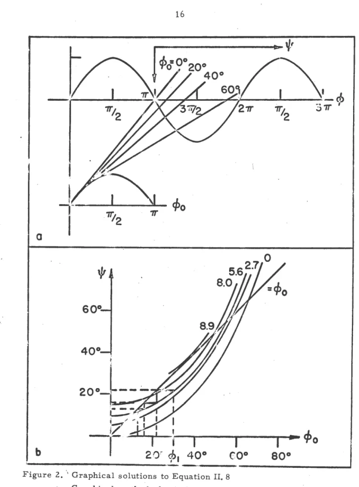
A graphical solution of this can now be made and the method
of doing ao ia shown in Figure 2a. The upper curve is the
right aide of Equation II.S and the lower curve the left side.
The point at which the tangent line from the lower curve
intersects the upper curve ia the solution for ' corresponding
to the particular ~0 of the lower curve.
Solutions of the electron arrival phase (') vs. the
initial phase (~0) as determined by the abo~e graphical method
are shown in Figure 2b. This figure provides the following
information a
a. For electrons with ~0 between 0° and 6~0 the electrons
move during successive cycles toward a single
par-ticular time phase indicated by the intercept of
the 4~0 line and the curve of interest.
b. For electrons with ~0 greater than 65° the electrons
move during successive cycles toward regions in
which the multipactoring process may no longer be
repeated.
This is a type of phase focusing or "bunching" of electrons
that provides stability in the oscillation. In Figure 2b an
example of this is shown for an electron emitted at the time
phase designated ~1• Successive time phases of arrival and
emission are shown by dashed lines, and show that the electrons
wil~ move toward a time phase of about 11° as a single
a
b
11';.
2t.::..~
;::"'"
i " .... , I
c/>o
r7
d::
-~-
I
I
I
€0°
I ...
~o
80° 20:-
cp.
40°i~---·-
-·---...1
Figure 2 . ., Graphical solutions to Equation II. 8
a. Graphical method of solution of Equation II. 8 for arrival phase 1/J
vs. emission phase (/J 0
b. Solutions of Equation· II, 8 for arrival phase 1/J vs. emission phase (/J (12)
Note alao that a aecond intercept of the 4~0 line ia
made by each curve of figure 2b. Thia aecond intercept ia1
however1 a phaae correaponding to phase defocusing and ia,
therefore, unstable with respect to sustaining the
multi-pactoring oscillation. If an electron happens to be oscil•
lating in this exact time phase it will remain there
indef-initely• however, if for some reason it arrivea slightly
earlier it will immediately drift to the lower synchronous
phase intercept. Similarly
if
it arrives alightly later itwill be lost to the oscillation, These •tability conditions
will be diacuased in more detail when the work of Krebs and
Meerbach ia discussed belowe
From this point the work becomes a detailed evaluation
of phase and energy relations which are of a qualitative
nature and not too useful. The significant point oi this work
was in demonstrating that time phases exist toward which all
electrons emitted over a wide range of ~0 values will bunch.
These will be ca~led in general, as above, synchronous time
phases.
The first work to take into account the initial electron
energy was done by Gill and von Engel (6), From Equation 11.4
they make the assumption that the electron arrives at X • a
at a time phase ~ • ~0
+
~, and since Sin (~0 + r)• - Sin ~0Equationa 11.3 and 11.4 become
a • (v0 + e
v
1 Cos ~0)~ + 2ev
1 Sin ~0 II.9- . (I)
va • v0
+
2ev
1 coa -0lllQ)8
where va la the arrival velocity of the electron at
X •
a.At 'thia point another aaaumption ia made that the ratio
v8/v0 • k, where k ia conatant. With tnia, Equations II.9
may be reduced to
II.lO
.
a
•{H-f
1T Coa-o
+ 2 Sin-~ ~
.mc.oa
Replacing now the angular frequency ~ by the wavelength ~
Equation• 11.10 become
The equation• were formulated in thia particular m.nner aince
the inveatigation waa into breakdown phenomena aa a function
of wavelength. The aecond of _Equation• 11.11 ia of use, for
it enables the breakdown potential to be determined for given
values of a, .k, and
/6
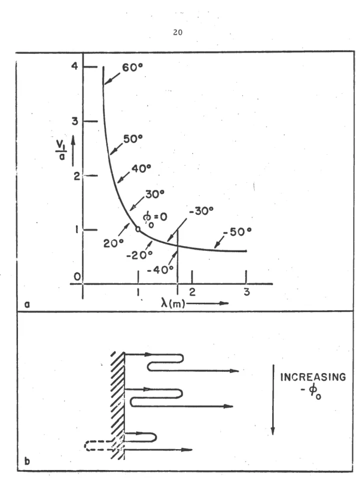
0 • One example of a solution to this iagiven in Figure 3a for k • 10.
Upon examination of Figure 3a one note• that electron•
a~e shown being emitted at rather large value• of negative
' '
/6
0 which correapond to large field• in the opposing directionthe electrodes have been treated as ideal grids and the fields
postulated to arbitrarily exist. Because of thi~electron
paths of the form shown in Figure 3b are mathematically pos•·
sible and correspond to the large ne~ative values of ~0• Since
it is obvious that physically th~ electrons cannot pass through .
the electrode, there must exist a limiting value of -¢0 for
any set of parameters.
A limiting value of -¢0 may be determined from the
equations above. Consider an electron emitted at the limiting •
time phase
·¢
0 with X=
0 and X=
v0 • It will at some later time phase -¢0,
corresponding to the second turning point in•
the paths of Figure 3b, have X = 0 and X = 0. Applying these
conditions to Equation II.ll yields
(~~ + ¢0)Cos ~~
=
Sin ~~ + Sin ¢0v0
=
ev
1 (Cos ¢~-
Cos ~0)-IOO>a
II.l2
then from the second. of Equations II.9 and the second of
Equations II.l2
k
=
va/v0 = Cos ¢~ + Cos ¢0 II.l3Cos ¢~ - Cos ¢0
From this equation a limiting value of
¢
0 may be found which for k=
10 corresponds to ¢0=
-400 and X. = 1.74 meters.The major significance of this work is that it gave a
good explanation for high frequency cut-off effects in
4
60°
/
3
-
~
f
40°
2
--
/
·
(
30°
/
-30°
cb=O
1 - / ro
-50°
20°
I
I
-20°
·
0
I
-4oo
-1
I
2
3a
~(m)~
~
)~(
..
INCREASING)
-cp
0..
r
~
b
Figure 3a. Solution of Equation II. 11 for k
=
10longer wavelength• the breakdown potential deer••••• ••
deacribed on Page l. Later work ahowed that a cut•off wave•
length, below which almoat no breakdown could occur, exists.
Experimental result• showed excellent agreement to a cut-off
of the form ahown in figure 3a.
The moat complete and experimentally verifiable work waa
done by Kreba (18) in 19~0 and by Kreba and Meerbach (21)
in 195~. The remainder of thia chapter will be devoted to
a review of their work. This work ia well verified in refer•
ence (21).
If in Equation II.~ it ia assumed that the electron
arrives at electrode 2 (for which X • a) at a time phase ~a
then Equation II.4 becomes
a = { e
v
1 Cos16
0+
::S}
(16
1rrm
2
a c.uDefine now the following parameter&
where
K = rrm2a2 1
~
•v
1/K 1 y • V .fK eeV • l/2 m v2 • 0
II.l4
II.l~
V1 ia the emiaaion energy of the electron• in electron volta.
Using the parameters of Equation II.l~, Equation II.4 becomes
1 • (~ Cos ~0 + ~)(16a •
/6
0 ) - p(Sin 161 - Sin16
0 )II.l6
One desires a solution for
16
1 as a function of16
0 from thisFigure 4a.
.,.
·Solutio~ of
of ¢0 for
r
"-, .
3'1; • '2
0
~
·
·
Equation II.l6 for ¢4 as a function
=
0
and ~=
parameter(21)
....
tPo
Figure 4b. Solution of Equation II.l7 for ¢r as a function of ¢0 with
J2Y/p
as a paremet er{21)
graphical ,solution for y a 0 and ~ as a parameter.
One notes in Figure 4a that a solution exists for emission
time phases in the range ~; ~ ¢0
<
0. This is the samesituation as discussed for the electron paths in Figure 3b.
At emission the electron sees a field that forces it back into
the electrodeJ however, mathematically it is po~sible to
accelerate the electron negatively through the ideal grid that
represents the electrode. The multiple solutions of the
equation that occur along the left and right.side of the curves
in Figure 4a correspond to different types of oscillations
about one or the other electrodes.
To obtain a limit on the time phase ¢0 let ¢r represent the time phase at which an electron emitted at ~0 and accel-erated negativ~ly will repass the electrode at X = 0. One
can solve for
¢r
by setting¢
=
¢r
and X=
0 in Equation II.4.By using the parameters defined in Equation II.l~ the
equa-~iQn satisfied is
(Cos
¢
0 +J2Y)
¢r -
Sin¢r
= (Cos¢
0 +J2Y)
¢
0 - Sin¢
0-r
--r
II.l7Solutions to Equation II.l7 are shown in Figure 4b with
~ as a parameter. Note that for
J2Y
>
1.26 no solutionsT
-
~exist. This shows that any time phase is possible for emission
in order to accelerate the electron positively, and corresponds
oppoaing field. The curve for ~ • 0 haa been plotted in
T
figure 4a aa a daahed line ahowing the limiting valuea for
y • o.
Now if an electron ia emitted from one electrode with
0 ~ - 0 ~ r it muat arrive and emit secondary electrons at the
other electrode at a time phase~~ such that T ~ -~ ~ ~.
Thia defines a set of effective region& for which the
multi-pactoring process may be set upa these regions are shown as
the non-hatched.regions of Figure 4a.
Figure ~a shows a solution of Equation 11.16 for a
non-zero value of y. In particular it shows the solution for
y • .0064 and ~
=
0.32. The limiting value of -0 as deter•mined by Equation II.l7 is shown as the dashed line and
indicates that for this.particular case electrons with ~0 values as low as -60o may successfully enter the
multipac-toring oscillation.
Examine now the successive emission phaaea of an electron
initially emitted at an angle - 0 in Figure 5a. This is
easi-ly done by reflecting each ~a back to the ~~ axi~ using the
unity slope line (designated • ~0 + ~). If thia is done it
is seen that a series of emission time phases~~'-~~,~~~~ •••
as shown in Figure ~a results which approach a limiting time
phase corresponding to point
s
1 • This 1& identically thesame phase focusing property ~s was shown to exist by
Figure
~b•Solution of Equati9n 11.16 forK-a
va.
~o for ~c0.32,I
=.0064 demonstrat1ng the principle o~phase focus•ng (~l ) 0.10 o." \ .,:a • 0 01 0.12 0.20 O.lO '
I I 1 ' f I
I I
I I
_.,,
"'·
~~ (1N$TAIILITAT VON)
•
f NACH 1111li
n = l existence region for two electrode
second time phase corresponding to point
s
2 of Figure 5a, andis a phase corresponding to an unstable equilibrium. A very
simple geometrical reason exists that explains why this occurs
and may be expressed as a constraint on the slope of the
solution curve at the points
s
1 ands
2. This condition is. d
!6
a
-
5.
1 II.l8d
!6o
_
!6a
=
!6o
+v
For any solution of Equation II.l6 that satisfies condition
II.l8 there will exist at least one time phase (which will be
designated by /6s and called the synchronou.s time phase) toward
which electrons emitted in the valid regions will focus very
quickly. An expression for these synchronous time phases /6s
may be obtained by setting ¢0 ~ ¢s and ¢a
=
/66 + n v (n= l, 3, 5, • • • ) in Equation II.l6. This yields¢s = + arc Cos
1
(1 - nv~) + arc tan _2_p n v
../4 + n21T2
II.l9
In order that Equation II.l9 be a real value, the
argu-ment of the arc Cos term must be less than one. If this is
applied to II.l9 the condition results that
~ ~ 1 - nv • ./2_:f
../4 + n21T2
II.20
This equation relates the magnitude of the r.f. voltage to
the frequency and electrode separation as an existence
•
defined in 11.1~. figure ~b ia a diagram of the values of the
parameters defined in 11.1~ for which a stable oacillation can
occur. The left hand boundary is formed by Equation 11.20.
In order to obtain an upper limit on the parameter ~ for
a given value of the parameter y, it is necessary to apply
the condition stated in 1!.18 to Equation 11.16. Wi~h ¢0 ~
¢
1and ¢a a
¢
1 + n~ one obtain& from 11.16d
-a
-a nrsin -.
+
~~~·
2 Co a
J
1 + J'};f/~The critical valuea of {66 for which jd ¢8/d ¢01 • 1 ia then
given by
nlrSin ¢8
+
./JR/p
::a :t 12Coa ¢1 +
,J1};(/p
The poaitive aign here yielda the reault
¢
8=
arc Tan_g_
n-r
which after aubatitution for
¢
1 from 11.19 leada aimply to11.20. However, the negative aign with the help of Equation
11.19 yielda an upper limit on ~ after aome algebra as
~
i /{
m -
nr ·}\ { 2 }2~
02;'2.
4n27T~-4
11.21
The value of ~ given by this in equality forma the right hand
boundary of the existence region shown in Figure 5b •
..
due to the fact that electrons are emitted prior to the
cut-off values of --0 aa one nears the lower y values in Figure
5b. The lower boundary as shown in Figure 5b that accounts
for this is determined from Equation II.l7. Also shown in
Figure 5b are lines of constant ¢s.
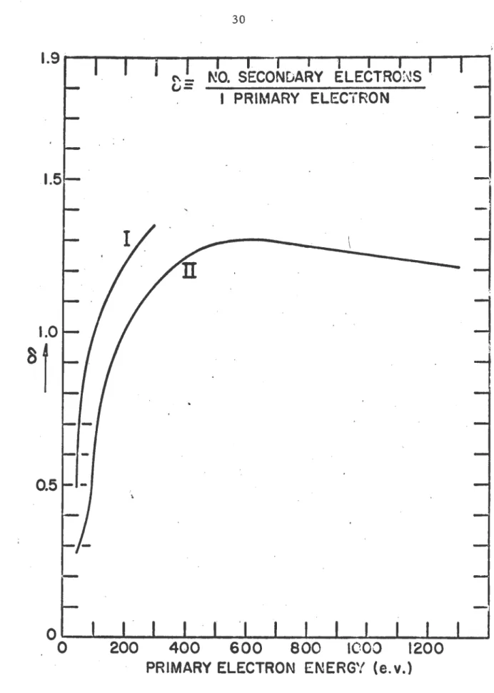
Thus far nothing has been said about the energy which an
electron possesses upon arrival at the opposite electrode.
That this is a necessary consideration may_be seen from
Figure 6 which is a graph of electron emission coefficient
as a function of primary electron energy for electrons
impinging on Copper
(3).
Unless the emission coefficient is greater than one the multipactoring process has no hopeof occurring which implies a certain minimum energy of arrival
is required.
An expression of the electron arrival velocity or energy
may be obtained from II.3 as
or
v
a = X¢ •=
{6 = v0{..JL
(Cos {60 - Cos {61 ) +1}
·, a
J'l.Y
where V1 is the electron arrival energy in e.v., and Equation
II.l5 haa been used. If this is restricted to synchronous
electron emission phases with ¢0 = {66 and ¢a
=
¢0 + v, and further use of II,l5 is made, it becomes11.22
Lines of conatant energy determined from this equation are
shown in Figure 5b.
Experimental work by Krebs and Meerbach (21) showed that
this mechanism is in excellent agreement with experiment for
vacuum pressures less than 10-5 torr. at least. In particulsr
their work showed total in~ependence of the mechanism with
respect to the gas in the vacuum. All prior 'work had been
. -4
done at gas pressures above 10 torr. and showed some gas
dependency in most cases. This however can be expected since
the electron mean free path becomes short enough to make sn
interaction between the electrons and the gas fairly likely
'·
0.5
'\
NO. SECONDARY ELECTRO~~S
I PRIMARY ELECTRON
-
--0~--~---~----.__.
__ .__. __ .__. __
~~~0 400 600 800 1000 1200
PRIMARY ELECTRON ENERGY (e. v.)
III. THEORY Of SIN3LE ELECTROOE MULTIPACTORIKi
In thia chapte~ a theory of the new form of
multipac-toring oacillation described in Chapter I will be developed •.
The conditions for the exietence of synchronoua time phaaee
will be· shown, and a method of specifying suitable parameter•
for experimental uae will be displayed.
A. Equation of Motion and Solu~iona
for Electron Arrival Phases
Here aa in Chapter II the motion will be considered one
dimenaionally for the geometry of Figure 7. Assume that
electrons are emitted normally at time phaae ~0 and velocity v8 from the plane electrode at
X
~o,
and that the field linea have no fringe effect& ji.e. the electric force on theelec-tron is perpendicular to the electrode plane at all points).
The electrode separation is designated by a, and the potential
as diagrammed in Figure lc has the form
v
=
v
0 -v
1 Si~t ~v
0 -v
1 Sin~where ~ • a>t and a> ~ angular 'frequency.
The equation of motion is then
..
III.l
, mX m •eE0 + eE1 Sin - III.2
where E0 • Vgia, El m
v
1/a, and e and m are the chargemagnitude and maas of the electron respectively. Integrating
•
X •
v
8 •e&
0 (- • - 0 ) +ee
1 ( Coa -0 • Coa -) 11I.3-
mro-
IIIQ)Integrating a aecond time yialda
X= •eE0
(~
• - 0 )2 + (eE1 Coa16
0·
+
ve)(- • - 0 ):::2
2JJb>:-2
lito-Q)
+
ee
1 (Sin ~0 - Sin -)rlto2.
Define now the following parameters
where Ve ia given by
III.4
III.!>
eve a 1/2 mv! III.6
V8 ia the emission energy of the electron• in electron volts.
Using the parameters defined in III.5 and III.6,
Equations III.3 and III.4 become
X
= -BQ>6(~
-~
0
)
+ BQ>ti (Cos~
0
- Coa~)
+(2eV.fml~
X za •al\
(~
-~
0
)
2 +a(~
Cos16
0 .+~)(~
•~
0
)
III. 72
+ a~(Sin
16
0 - Sin~)Recall that in this form of multipactoring oacillation
tht electron ia multiplied when it again impingta upon the
original electrode from which it was emitted. Thus from the
aecond of Equations III.7 a solution is desired for the time
phase at which the electrons emitted from X
=
0 at time phase·(a) Path of electron in stable 2r electron oscillation (b) Mathematically possible path of electron emitted in
strongly opposing electric field
·
('cl
.
Mathematically equ.ivalent path of (b) for ·electron. ' -~tted negatively
. (d) Mathematically similar path to ·(b) but with less
· opposing field .
·(e) Path of electron emitted·with sufficient· energy to overcome a small opposing field and enter ~ stable .ultipactoring oscillation
(Vertical displacements are for clarity only; they do not
·exist in the actual . process)
,_
..
0
LLI
-
0--
0-
.D-.
-)(
I
I
~-~I
\
-
Q)-
•-
"0-phaae will be dtai;nated the arrival -phaae -., and ia obtained
by aettin; X • 0 and- • ' • in Equation III,7. Thia yielda,
after diviaion by
·•A•
o •
(i1 -
ai1 )
o 2 - (" · Cosi1
o+
./'i.Vy)(i1 -ai1 ) •
o~
(Sini1
0 • Sin i1a)2 -;;:
6
:A
Define now two new parameter•
a •
~ a El/Eo • Vl/Vo:A
.
G a ~ =
v
8K/E0a
ll/
(
III.8Then with aubatitution of these parameter• the equation becomes
0 a (i1a • i10 )2 • (a Cos
J
0+
G) (,Ia • i10 ) • B(tSini1
0 • Sin i1a)2
111.9
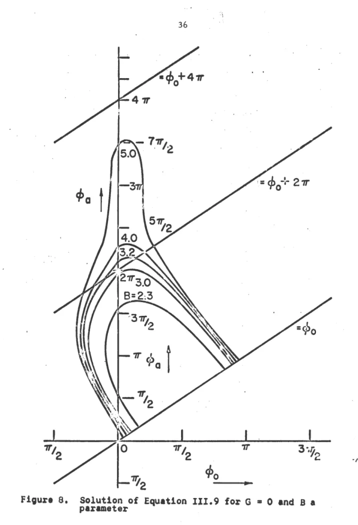
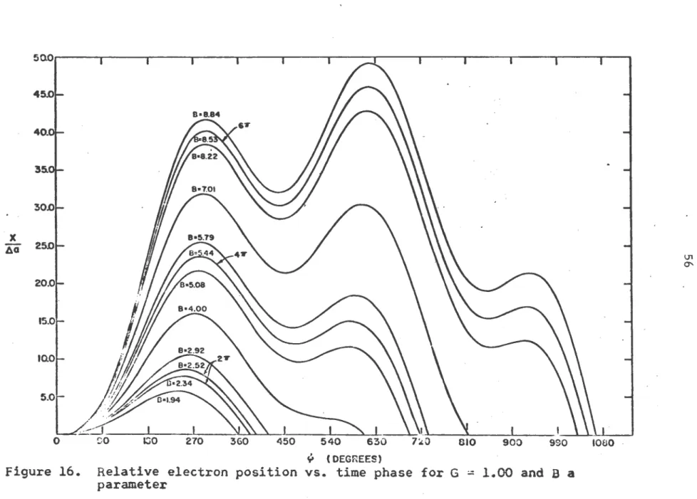
Solutions of Equation I~I.9 for i18 as a function of
i1
0 areshown in Figures a, 9, and 10 for G values of
o.o,
o.o~, and1.00 respectively. B. is a parameter in each of these curves.
Inspection of figures a, 9, and 10 shows that for many
values of "0 the solution is multivalued with as many as
three aolutions. These multiple solutions correspond to the
several possible electron paths, some of which are diagrammed
in Figure 7. For
example
an electron emitted with ~0 • 10°for G • 0 and
a •
3.~ has two solutions ,a=
2a0 and ,a = 3a4o.Thia corresponds to an electron being accelerated negatively
first, then pasaing through X
=
0 at " :::: 28° and subsequentlyreturning again to X • 0 at
i1
=
384° as diagrammed in the path'
I
I
I
.,
cl>o
Figure
a.
Solution of Equation 111.9 for G=
0 and B afigure 9,
I
.,.
-~~-~-
cflo
,r FigUI"&
10.
~at
.
1T
f
~)0 -~
-1i/.
so1utron
o~Equation
III.9 for G • 1.0 and B a
fields exist in apaee independent of any electrodes (which
appear aa tranaparent grida) the path labeled c is identically
equivalent to the path l~beled b. An example of three
solu-tions is given by an electron emitted at ~0 ~ •400 for G • 1.0
and B = 2.9 in Figure 10 and the corresponding path is shown
as d in Figure 7.
The multiple solutions arise in the following fashion.
If electrons are emitted prior to time phase ; in Figure lc
the electron can be accelerated in a negative direction
providing it does not have sufficient energy to overcome the
opposing field. For the case G ~
o,
or zero emission energy,this will occur just before the time phase ; at which the net
field is zero. From Equation III.l this time phase ; is given
by
Sin ;
=
1/B III.lOIf however, the electron has an initial energy it can
overcome a bit of opposing field. It can then successfully
leave the X ~ 0' electrode at a time phase somewhat earlier
than ; and still be accelerated positively at a later time.
This case is shown in path e of Figure 7. Now since G is an
increaaing function of the emission energy (c.f. Equation
111.8), the region of multiple solutions ahould move toward
more negative ~0 values as G increases. This indeed occurs
as is seen by comparing Figures
a,
9, and 10.For practical purposes of the multipactoring oscillation,
solution for -a· The range of -0 values that have aingle
solutiona for -a increaaea for incraaaing G valuea for. the same reason that the region of multiple aolutiona moves toward
larger negative ~aluea of ~0 with increasing values of G. Chapter X containa a full set of solution& of Equation
III.9 for ~a va. ~0 for a range of G values from 0.0 to 1.~.
B. Phase Stability and Existence Regions
The general condition for sustaining a single electrode
multipactoring oscillation is that a synchronous time phase
exists such that the electron returns to the emitting
ele'-trode nv (n ~ 2, 4, 6, o o .) later in time phase than it was
emitted. These synchronous time phases may be determined by
setting ~0 : ¢6 and ¢a.= ¢1 + nv in Equation IIIo9 and solving
for ¢6o Doing this yields
0 a
n2v
2 - nv (B Cos~. +
G)--r
and solving for.¢8
- . a ± arc Coa (nv - 2G)
2a
III.llwhere n • 2, 4, 6, • • • corresponding to the case of an
electron returning to X • 0 at timaa
~. 4V, 6Tphase respectively.
•
•
•
later
inIn the curves of Figures
a,
9, and 10 these values of¢
1 correspond to the intercepts of the solution curves with theline designated- • ~0 + 2". This immediately suggests a
~in~ercept of the aolution curve with the - • -0 + 2r line. Thia ia identically the aaae as saying that jcoa
-.11
1. From Equation III.ll this condition yieldsn'IF' •. 2G
<
12a
-or
B ~ nv - G
T
IIFor G • 0 and n ~ 2 thil yields that B~. T ~ 3~14.
111.12 .
Examina•
tion.of Figure 8 ah~wa that this value of B corresponds to
the solution curve be~oming just tangent to the ~0 + 2r line.
For B • .,. and G • 0 Equation 111.11 shows that 11~
•
0° as thesynchronous phase angle1 however, this is not an allowable
phase becauae it ia in the region of multiple aolutions and
the electron will be a~celerated negatively first.
The very fact that the
i1
=
i1
0 + 2V line intersect& thesolution curve for i11 is sufficient to say that at least one
synchronous time phase exists. However, the question is now asked as to whether these time phases correspond to stable or
unstable equilibrium with respect to sustaining the
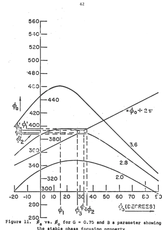
multi-pactoring process. Examination of Figure ll shows that a stable condition muat exist, and Figure 12 shows an unstable
condition exis.ta. In Figure 11 the successive emission and
arrival phases for an electron emitted at
i1
0 ~ 15° forG
=
0.7~ and B ~ 2,8 are examined and it is found that phase~ . ~ 0
focusing occurs toward the synchronous phase p 8 z 3l given
300
-20 -10
0
290
50
so
70
eo
~· J\~
0
(CC:C.REES)·
2GO
I I I I
I I
r:
-i----1
I I I I
I I
I
II I I 2.0 I
I I
I
I
I , .I
I I I I I
·20 -10 10 20 30 60 70
~0
.,.
140 50
°'
93
9.
cp2
94
'cp1
rp6
I
·260
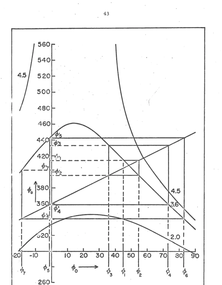
and arrival phaaea for an electron emitted at - 0 a 45° for
G •0.75 and B • 3.6 are examined and it is seen that a phaae
.
defocusing effect occura in which the electron wanders from
phase to phase over a wide region.
Examination of Figures
s,
9, 10, 11, 12 and the curvesin the Appendix ahows that the same geometrical stability
condition for phase focusing exists for the aingle electrode
process aa for the two electrode p.rocesa discussed in Chap•
ter II. Thia condition is
d ~a
i
1dTa
~0
=
~.
/A
8=
/A
1 + ntrThis ia just a geometrical condition on the alope of the
solution curve at one ~oint. From Equation 111.9 one obtains
d
~-/d [A0 • (1-B
Sin ~0)(~a • ~0) •G
(/A
8 -/A
0 ) - B(Cos ~0 - Cos ~a) • GFor ~0 • -s and,~8 • •s
+
nw this last equation becomeswhere n • 2, 4, 6, • •
•
+ nr
=
(1 - B Sin ~8) nr • G ntr - GIII.l3
Applying the geometrical condition
to Equation III.l3 yielda a positive and negative case which
will be conaidered separately.
Negative £!.!.!.
get a
After rearranging·, th1t becomes
.
'B Sin ~s ~ 2(nr • G) nr
From Equation III.ll
Sin j 1 •
±
{4
a
2 - (nv • 2Gl
2 }JS
2 8 . 111.14
Substituting for Sin j11 and solving out using the + sign in Equation 111.14 (c~rresponding to 0 ~ ¢1 ~ r) .yi8lda
B
~
1/2 {16(nv - G) 2 + (nv - 2G) 2}~
r&2JT2 .
Positive case
-From Equation III.l3 and ~he geometrical condition one
gets
( 1 • B Sin ~ 8 ) n1r • G ~ n1r • G
or
B Sin
/t1
1 ~ 0The condition must then be that Sin ¢s ~ 0 since a 0 value
of zero would represent a trivial case. Hence using Equation
111.14 above yields
{ 4
s
2 • ( n1r .. 2G) 2 }JS
~
o
2
s
and solving for B yields
B
- y
>
nv - Gwhich was obtained previously.
Combining the two boundary expressions yields
{ n1r - G}
.i
B.i
J4(n1r - Gl2+
{n'lr - 2Gl2}~
111.15·
T
·
\
n~
2 4 .valid for 0
.S.
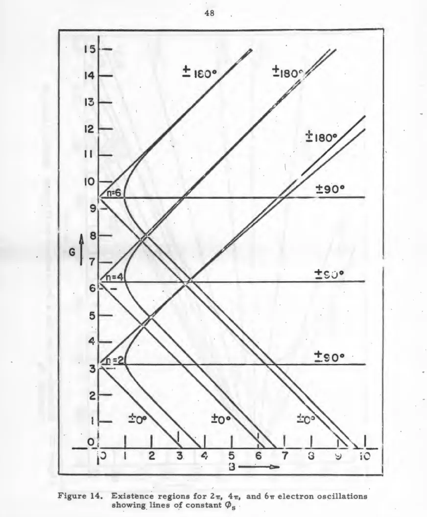
-s .S. "· Solutions of Equation 111.1~ for theequality or boundary conditions are shown in Figure 13 for
n
=
2, and in Figure 14 for n=
2, 4, and 6. Linea of constant~~ are also shown corresponding to the particular values of
B and G as given in Equation III.ll.
Examination of Figures
a,
9, and 10 and Equation III.llshow that in the stable regions of Figures 13 and 14 two
values of the synchronous phase exist symmetrical about ~0 = 0°.
For lower G values the negative ~. is for the most part
use-leas due to the cut-off of allowable -0 values. However, for
high G values the negat~ve ~s value is allowable, but always
corresponds to an unstable equilibrium condition,
correspond-ing to phase defocuscorrespond-ing, on the multipactorcorrespond-ing process.
Electrons exactly at these negative ~. values will remain
there indefinitely, but any small displacement in time phase
will result iri a drift toward the positive ~s solution. For
B values greater than the stable values of Equation III.l~
both ~s phases become unatable and the electron& drift
con-tinuously from one phase to another.
That the negative-. time phases posse~phase defocusing
properties may be aeen by using the geometrical condition and
Equation III.l3. Sin-. in Equation III.l4 is negative for
4.5
+1o5o
-±goo
±soo
1.0 ·.
:--...
Q~r
j_, ,
I
-~
05
B -
-
- - -
-
~
-
·
L
I
Figure 13.
1.0 3.5 4.0
Existence region for a 2U electron oscillation showing lines of constant
!6
5tJ>.
15-14
13
12
I I
+e_..,;v ··.o
5
+e
- v,
oo
.
0~
I
-
-
-
··- ·jJ
2
3.4
5
6 7 G ~ iC3 c.
Sin ~8 ~ 0
and subatitutin9 from 111.14 for Sin ~.
hence
-{ 4
s
2 • ( nT • 2G) 2} JS~
02 B
II1.16
However, if this condition is satisfied the ;solution curves
will never intersect the ~ =
¢
0 + nT line except at one point.This of course is the case in which there will be only one ~s
intercept and corresponds to tangency of the solution curve to
the straight line. From this it must be concluded that values
of ~~ in the region 1r ~ ~~
S
21r represent phasescorrespond-ing to phase defocuscorrespond-ing, and thus are not phases of stable
equilibrium with respect to the propagation of the
multi-pactoring oscillation.
c.
Electron Return EnergyIt was aeen in Chapter II that the return energy of the
electrons plays an important part in whether a sufficient
number of electrons are emitted from the electrodes to produce
a stable multipactoring or not. Figure 6 demonstrates that an
insuffi~ient return energy will produce an emission coefficient less than 1, and too high a return energy will decrease the
emission coefficient very close to unity. It is therefore
Let~ repreaent one period of the r.f. voltage, and vr
be the return velocity of the electron at time phaae ~.. For
a nrr(n a 2, 4, 6, • • • ) electron transition the return
velocity vr fQr a synchronous phase ia obtained from the
Impulse-Momentum Principle by int_egrating over a full cycle
of the r.f. aa
Evaluating the .integral
-a/O>
+lj
'•/m
+ '1:'nJFdt • ·eE0 Jdt ·
2
+
-s/co 16a/m
hence
+ '1:'n
2
.
16
1/Q) + l!!eEl
I
Sin Q)tctt2 a16,;(&)
vr·• v8 - eE0'1:'n
2m
III.l7
Squaring and multiplying by ~2 yields the return energy (W)
a a
W •
l/2
mv; a l/2mv~
- •veE0:2n +e
2E~'1:'
2n
2am
But E0 • Vglat l/2mv~
• ev8 , and '1:' a l/f, henceBy further uae of Equationi .III.5 and III.8 thia can be
W a eV
+
n~ eV_A(nv • G) (mechanical units)•
c;r-2
III.l8
w •
v
+ n~_A(nv • G) (electron volta)e o-
2
Thi1 equation is valid for a nv electron transition in the
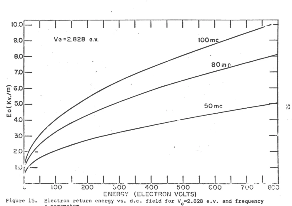
aynchronous multipactoring process. Figure 1~ shows several
solutions to Equations III.l8 for V8
=
2.828 e.v., n a 2,and frequency as a parameter. It ia evident from this that
reasonable electron energies may be obtained with not too
high a d.c. field.
A similar method obtains the energies for an electron
emitted in a non-synchronous time phase. In this case the
electron does not return to the emitting electrode an integral
number of periods of the r.f. cycle later. The energy can be
determined, however, in the following manner.
At some time phase-Q the electron will atop and be
accelerated back toward the multipactoring electrode as a
final step in a sequence of back and forth motions. This
.
timt phase may be determined from Equation III.7 for X= 0 as
~
0
=
-aw6(~ - ¢0 ) + a~ (Cosi1
0 - Cos ~) + (2eV e)m
Using the abbreviations of Equation III.S this becomes
Q + B Cos Q = ¢0 + B Cos ¢0 + G
In general, for high B valuea this equation ia multivalued with solutions corresponding to each turning point of the electron's path (aee Figure 7)1 th~refore, it will be convenient to
index the solutions for Q with a subscript m as
..
.>
~ 5.0
1-·
-• I
L_
.
t_l
J
=L
I
_j
I
l
I
I
I
L.
.
~I_
\..
100
200
~00400
500
coo
1oo
eco
ENERGY (ELECTRON VOLTS)
Figure 15. Electron return energy vs. d.c. field for V8=2.828 e.v. and frequency
a parameter ·